CN218816862U - Air compressor machine waste heat recovery utilizes device - Google Patents
Air compressor machine waste heat recovery utilizes device Download PDFInfo
- Publication number
- CN218816862U CN218816862U CN202222843142.7U CN202222843142U CN218816862U CN 218816862 U CN218816862 U CN 218816862U CN 202222843142 U CN202222843142 U CN 202222843142U CN 218816862 U CN218816862 U CN 218816862U
- Authority
- CN
- China
- Prior art keywords
- air compressor
- box
- fixedly connected
- heat
- water tank
- Prior art date
- Legal status (The legal status is an assumption and is not a legal conclusion. Google has not performed a legal analysis and makes no representation as to the accuracy of the status listed.)
- Active
Links
Images


Landscapes
- Other Air-Conditioning Systems (AREA)
Abstract
The utility model provides an air compressor machine waste heat recovery utilizes device, comprising a base plate, the last fixed surface of bottom plate is connected with four first support columns and four second support columns, four the last fixed surface of first support column is connected with a first box, four the last fixed surface of second support column is connected with a second box, air compressor machine of inner wall bottom fixedly connected with of first box. The utility model has the advantages that: be provided with heat pipe and draught fan, the air compressor machine during operation time body itself can generate heat, the heat that gives off can be under the effect of draught fan through the inside of the leading-in second box of heat pipe, the inside water tank that is provided with of second box, through a plurality of heat-conducting plates, can promote the efficiency of heat absorption, for the inside water heating of water tank, the motor can drive the water tank and rotate, can make the water in the water tank be heated more evenly, can utilize the heat that the air compressor machine during operation gave out effectively, be of value to the energy saving.
Description
Technical Field
The utility model relates to an air compressor machine technical field, especially an air compressor machine waste heat recovery utilizes device.
Background
The air compressor is a device for compressing gas, collects heat energy generated in the operation process of the air compressor through energy exchange and energy-saving control, improves the operation working condition of the air compressor, and is energy-saving equipment with high-efficiency waste heat utilization and low-cost operation.
The air compressor machine can give out the heat at the in-process that uses, and to these heat recovery utilization be favorable to the energy saving, current air compressor machine waste heat recovery's equipment can't high-efficiently realize the heat recycle to air compressor machine organism and combustion gas.
Therefore, the waste heat recycling device for the air compressor is provided and solved.
SUMMERY OF THE UTILITY MODEL
The purpose of the present invention is to solve at least one of the technical drawbacks.
Therefore, an object of the utility model is to provide an air compressor machine waste heat recovery utilizes device to solve the problem mentioned in the background art, overcome the not enough that exists among the prior art.
In order to achieve the above object, an embodiment of an aspect of the utility model provides an air compressor machine waste heat recovery utilizes device, comprising a base plate, four first support columns of last fixed surface of bottom plate and four second support columns, four first box of last fixed surface of first support column is connected with, four second box of last fixed surface of second support column is connected with, air compressor machine of inner wall bottom fixedly connected with of first box, motor of inner wall bottom fixedly connected with of second box, water tank of output fixedly connected with of motor.
Preferably, by any of the above schemes, the lower surface of the water tank is fixedly connected with four support rods, the bottom of the inner wall of the second box body is provided with a circular groove, and the inner surface of the circular groove is connected to the outer surfaces of the four support rods in a sliding manner.
Preferably, according to any one of the above schemes, the upper surface of the first box body is fixedly connected with a first cover plate, one side of the first cover plate is provided with a through hole, the inner surface of the through hole is fixedly connected with a heat conduction pipe, and the outer surface of the water tank is fixedly connected with a plurality of heat conduction plates.
By any of the above schemes preferred, a first heat insulating sleeve is sleeved on the outer surface of the heat conducting pipe, and one end of the heat conducting pipe is fixedly connected with an induced draft fan.
Preferably, in any of the above solutions, a second cover plate is fixedly connected to an upper surface of the second box, and an outer surface of the heat pipe is fixedly connected to an inside of the second cover plate.
By any of the above scheme preferred, the inner wall bottom fixedly connected with two electric putter of first box, two electric putter's equal fixedly connected with fixed plate of output.
In any of the above schemes, preferably, a second heat insulation sleeve is sleeved on the outer surface of each of the two electric push rods.
Preferably, according to any one of the above schemes, two anti-slip pads are fixedly connected to the lower surface of the bottom plate.
Compared with the prior art, the utility model has the advantages and beneficial effects do:
1. the utility model discloses the device is provided with heat pipe and draught fan, the time body itself can generate heat when the air compressor machine is worked, the heat that gives off can be under the effect of draught fan through the inside of the leading-in second box of heat pipe, the inside water tank that is provided with of second box, through a plurality of heat-conducting plates, can promote the efficiency of heat absorption, for the inside water heating of water tank, the motor can drive the water tank and rotate, can make the water in the water tank be heated more evenly, can utilize the heat that the air compressor machine during operation gave out effectively, be of value to the energy saving.
2. The utility model discloses the device is provided with electric putter and fixed plate, starts electric putter for the fixed plate moves down, can realize being provided with bracing piece and ring groove to the fixed action of air compressor machine, when the water tank rotated, four bracing pieces can slide at ring inslot portion, can play the effect of support to the water tank, make the water tank more stable when rotating.
Drawings
The above and/or additional aspects and advantages of the present invention will become apparent and readily appreciated from the following description of the embodiments, taken in conjunction with the accompanying drawings of which:
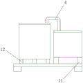
fig. 1 is a schematic diagram of a first viewing angle structure according to an embodiment of the present invention;
fig. 2 is a schematic diagram of a second perspective structure according to an embodiment of the present invention;
fig. 3 is a schematic front view structure according to an embodiment of the present invention;
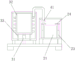
fig. 4 is a schematic structural view of a front cross-sectional view according to an embodiment of the present invention.
Wherein: 1-bottom plate, 2-first box body, 3-second box body, 4-heat conduction pipe, 11-first supporting column, 12-second supporting column, 13-non-slip mat, 21-air compressor, 22-first cover plate, 23-electric push rod, 24-fixing plate, 31-motor, 32-water tank, 33-supporting rod, 34-second cover plate and 41-induced draft fan.
Detailed Description
Reference will now be made in detail to embodiments of the present invention, examples of which are illustrated in the accompanying drawings, wherein like reference numerals refer to the same or similar elements or elements having the same or similar function throughout. The embodiments described below with reference to the drawings are exemplary and intended to be used for explaining the present invention, and should not be construed as limiting the present invention.
In the present invention, unless otherwise expressly specified or limited, the terms "mounted," "connected," and "fixed" are to be construed broadly and may, for example, be fixedly connected, detachably connected, or integrally connected; can be mechanically or electrically connected; they may be connected directly or indirectly through intervening media, or they may be interconnected between two elements. The specific meaning of the above terms in the present invention can be understood according to specific situations by those skilled in the art.
As shown in fig. 1 to 4, the utility model discloses an air compressor machine waste heat recovery utilizes device of embodiment, including bottom plate 1, four first support columns 11 and four second support columns 12 of last fixed surface of bottom plate 1, first box 2 of last fixed surface of four first support columns 11, second box 3 of last fixed surface of four second support columns 12 is connected with, air compressor machine 21 of inner wall bottom fixedly connected with of first box 2, motor 31 of inner wall bottom fixedly connected with of second box 3, water tank 32 of output fixedly connected with of motor 31, the air intake has been seted up to one side of first box 2, the air outlet has been seted up to one side of second box 3, can be convenient for inside steam flow through setting up of air intake and air outlet, so that better recovery waste heat.
Four bracing pieces 33 of lower fixed surface of water tank 32, a circular groove has been seted up to the inner wall bottom of second box 3, and the internal surface sliding connection in four bracing pieces 33's surface of circular groove is provided with bracing piece 33 and circular groove, and when water tank 32 rotated, four bracing pieces 33 can slide at circular groove inside, can play the effect of support to water tank 32 for it is more stable when rotating water tank 32.
The surface of heat pipe 4 has cup jointed a first radiation shield, and the one end fixedly connected with of heat pipe 4 draught fan 41, draught fan 41 can carry the inside heat of first box 2 inside the second box 3.
A second cover 34 is fixedly connected to the upper surface of the second housing 3, and the outer surface of the heat pipe 4 is fixedly connected to the inside of the second cover 34.
Two electric putter 23 of the inner wall bottom fixedly connected with of first box 2, fixed plate 24 of the equal fixedly connected with of output of two electric putter 23 is provided with electric putter 23 and fixed plate 24, starts electric putter 23 for fixed plate 24 downstream can realize the fixed action to air compressor 21.
And a second heat insulation sleeve is sleeved on the outer surfaces of the two electric push rods 23.
Two non-slip mats 13 are fixedly connected to the lower surface of the bottom plate 1.
Compared with the prior art, the utility model discloses for prior art have following beneficial effect:
1. the utility model discloses the device is provided with heat pipe 4 and draught fan 41, the time body itself can generate heat when air compressor machine 21 works, the heat that gives off can be under the effect of draught fan 41 through the inside of the leading-in second box 3 of heat pipe 4, 2 inside water tank 32 that are provided with of second box, through a plurality of heat-conducting plates, can promote the efficiency of heat absorption, for the inside water heating of water tank 32, motor 31 can drive water tank 32 and rotate, can make the water in the water tank 32 be heated more evenly, can utilize the heat that air compressor machine 21 during operation gave out effectively, be of value to the energy saving.
2. The utility model discloses the device is provided with electric putter 23 and fixed plate 24, starts electric putter 23 for fixed plate 24 moves down, can realize being provided with bracing piece 33 and circular groove to the fixed action of air compressor machine 21, when water tank 32 rotated, four bracing pieces 33 can slide in circular groove inside, can play the effect of support to water tank 32, make water tank 32 more stable when rotating.
In the description herein, references to the description of the term "one embodiment," "some embodiments," "an example," "a specific example," or "some examples," etc., mean that a particular feature, structure, material, or characteristic described in connection with the embodiment or example is included in at least one embodiment or example of the invention. In this specification, the schematic representations of the terms used above do not necessarily refer to the same embodiment or example. Furthermore, the particular features, structures, materials, or characteristics described may be combined in any suitable manner in any one or more embodiments or examples.
It will be understood by those skilled in the art that the invention, including any combination of the elements of the above description and the detailed description and illustrated in the accompanying drawings, is not limited to the details and should not be construed as limited to the embodiments set forth herein for the sake of brevity. Any modification, equivalent replacement, or improvement made within the spirit and principle of the present invention should be included in the protection scope of the present invention.
Although embodiments of the present invention have been shown and described, it is to be understood that the above embodiments are exemplary and should not be construed as limiting the present invention, and that changes, modifications, substitutions and alterations can be made to the above embodiments by those of ordinary skill in the art without departing from the principles and spirit of the present invention. The scope of the invention is defined by the appended claims and equivalents thereof.
Claims (8)
1. The utility model provides an air compressor machine waste heat recovery utilizes device which characterized in that: including bottom plate (1), four first support columns (11) and four second support columns (12), four of last fixed surface of bottom plate (1) are connected with first box (2), four of last fixed surface of first support column (11) the last fixed surface of second support column (12) is connected with a second box (3), air compressor machine (21) of inner wall bottom fixedly connected with of first box (2), motor (31) of inner wall bottom fixedly connected with of second box (3), water tank (32) of output fixedly connected with of motor (31).
2. The air compressor waste heat recycling device of claim 1, characterized in that: the lower fixed surface of water tank (32) is connected with four bracing pieces (33), a circular groove has been seted up to the inner wall bottom of second box (3), the internal surface sliding connection in the surface of four bracing pieces (33) of circular groove.
3. The air compressor waste heat recycling device of claim 2, characterized in that: the upper surface fixed connection of first box (2) has one first apron (22), a through-hole has been seted up to one side of first apron (22), the internal fixed surface of through-hole is connected with one heat pipe (4), the external fixed surface of water tank (32) is connected with a plurality of heat-conducting plates.
4. The air compressor waste heat recycling device of claim 3, characterized in that: the surface of heat pipe (4) has cup jointed a first radiation shield, the one end fixedly connected with draught fan (41) of heat pipe (4).
5. The air compressor waste heat recycling device of claim 4, characterized in that: the upper surface of the second box body (3) is fixedly connected with a second cover plate (34), and the outer surface of the heat conduction pipe (4) is fixedly connected to the inside of the second cover plate (34).
6. The air compressor waste heat recycling device of claim 5, characterized in that: the inner wall bottom fixedly connected with two electric putter (23) of first box (2), two the equal fixedly connected with fixed plate (24) of output of electric putter (23).
7. The air compressor waste heat recycling device of claim 6, characterized in that: and the outer surfaces of the two electric push rods (23) are sleeved with a second heat insulation sleeve.
8. The air compressor waste heat recycling device of claim 7, characterized in that: the lower surface of the bottom plate (1) is fixedly connected with two anti-skid pads (13).
Priority Applications (1)
| Application Number | Priority Date | Filing Date | Title |
|---|---|---|---|
| CN202222843142.7U CN218816862U (en) | 2022-10-27 | 2022-10-27 | Air compressor machine waste heat recovery utilizes device |
Applications Claiming Priority (1)
| Application Number | Priority Date | Filing Date | Title |
|---|---|---|---|
| CN202222843142.7U CN218816862U (en) | 2022-10-27 | 2022-10-27 | Air compressor machine waste heat recovery utilizes device |
Publications (1)
| Publication Number | Publication Date |
|---|---|
| CN218816862U true CN218816862U (en) | 2023-04-07 |
Family
ID=87042887
Family Applications (1)
| Application Number | Title | Priority Date | Filing Date |
|---|---|---|---|
| CN202222843142.7U Active CN218816862U (en) | 2022-10-27 | 2022-10-27 | Air compressor machine waste heat recovery utilizes device |
Country Status (1)
| Country | Link |
|---|---|
| CN (1) | CN218816862U (en) |
-
2022
- 2022-10-27 CN CN202222843142.7U patent/CN218816862U/en active Active
Similar Documents
| Publication | Publication Date | Title |
|---|---|---|
| CN209329104U (en) | A kind of new energy car battery temperature adjusting body | |
| CN206059459U (en) | A kind of temperature control battery bag | |
| CN115332563A (en) | Double-effect heat dissipation structure based on multi-stack fuel cells | |
| CN205536934U (en) | Waste heat recovery oven | |
| CN218816862U (en) | Air compressor machine waste heat recovery utilizes device | |
| CN212227542U (en) | Gypsum model drying device for architectural design | |
| CN108344260A (en) | Wood industry plank drying unit | |
| CN113555631A (en) | Air-cooled radiating battery | |
| CN208720326U (en) | A kind of carbon fiber electric warmer | |
| CN206419994U (en) | A kind of kitchen range of utilization thermo-electric generation | |
| CN210153929U (en) | High-efficient heat accumulation formula electric heater | |
| CN212380485U (en) | Air-cooled radiating battery | |
| CN214046449U (en) | Heat radiation structure of power | |
| CN210640277U (en) | New energy battery guard box that protectiveness is good | |
| CN212991210U (en) | New forms of energy heat supply conversion equipment | |
| CN208457983U (en) | Thermal accumulating incinerator RTO heat energy recovery equipment | |
| CN211321294U (en) | Solar cell with good heat dissipation effect | |
| CN213238525U (en) | Heat energy recycling device of heat energy power equipment | |
| CN211120344U (en) | Powder box convenient to move | |
| CN219934326U (en) | Energy-saving air source heat pump | |
| CN111198122A (en) | Drying cabinet for rubber product detection | |
| CN219322280U (en) | Inverter protection structure and inverter | |
| CN107314627A (en) | A kind of good accumulator plate drying unit of protecting effect | |
| CN214620477U (en) | Sunning device of sealwort | |
| CN215143480U (en) | Photovoltaic frame extrusion temperature control equipment |
Legal Events
| Date | Code | Title | Description |
|---|---|---|---|
| GR01 | Patent grant | ||
| GR01 | Patent grant |