CN218816632U - Expansion tank and vehicle - Google Patents
Expansion tank and vehicle Download PDFInfo
- Publication number
- CN218816632U CN218816632U CN202223055438.9U CN202223055438U CN218816632U CN 218816632 U CN218816632 U CN 218816632U CN 202223055438 U CN202223055438 U CN 202223055438U CN 218816632 U CN218816632 U CN 218816632U
- Authority
- CN
- China
- Prior art keywords
- tank
- expansion tank
- cavity
- main body
- expansion
- Prior art date
- Legal status (The legal status is an assumption and is not a legal conclusion. Google has not performed a legal analysis and makes no representation as to the accuracy of the status listed.)
- Active
Links
- XLYOFNOQVPJJNP-UHFFFAOYSA-N water Substances O XLYOFNOQVPJJNP-UHFFFAOYSA-N 0.000 claims abstract description 68
- 239000007788 liquid Substances 0.000 claims abstract description 19
- 238000009423 ventilation Methods 0.000 claims abstract description 11
- 238000009434 installation Methods 0.000 claims description 8
- 239000000110 cooling liquid Substances 0.000 abstract description 20
- 239000002826 coolant Substances 0.000 abstract description 10
- 238000000034 method Methods 0.000 abstract description 5
- 238000007599 discharging Methods 0.000 description 2
- 239000000463 material Substances 0.000 description 2
- 238000000926 separation method Methods 0.000 description 2
- 239000007787 solid Substances 0.000 description 2
- 238000007792 addition Methods 0.000 description 1
- 230000004075 alteration Effects 0.000 description 1
- 238000005260 corrosion Methods 0.000 description 1
- 230000007797 corrosion Effects 0.000 description 1
- 230000007423 decrease Effects 0.000 description 1
- 238000010586 diagram Methods 0.000 description 1
- 238000012986 modification Methods 0.000 description 1
- 230000004048 modification Effects 0.000 description 1
- 238000006467 substitution reaction Methods 0.000 description 1
Images


Landscapes
- Filling Or Discharging Of Gas Storage Vessels (AREA)
Abstract
The utility model provides an expansion tank and a vehicle, which comprises a tank body, a tank cover and a waterproof vent valve; the box body comprises a body and a neck part, the body is provided with a cavity, the neck part protrudes out of the body, and the neck part is provided with an opening and a port which are communicated with the cavity; the water tank cover is connected to the neck part and used for closing the opening; the waterproof ventilation valve is connected to the interface and is set to allow the air in the cavity to pass through. Because the waterproof vent valve is used for replacing an air overflow pipe of the traditional expansion water tank, when the expansion water tank performs a necessary air exhaust function, the waterproof vent valve can effectively prevent the cooling liquid from being discharged. Thereby solved traditional expansion tank's exhaust in-process, the coolant liquid can be along with gaseous exhaust, leads to technical problem such as coolant liquid loss, coolant liquid corruption cabin part.
Description
Technical Field
The utility model relates to an automobile design field especially relates to an expansion tank and vehicle.
Background
As shown in fig. 1-3, wherein the solid arrows in fig. 3 are liquid circulation loops and the dashed arrows are gas circulation loops. The gas-liquid separation process of the traditional expansion water tank comprises the following steps: system pressure rise → expansion tank cap open → gas/liquid pass through expansion tank cap → discharge via the pilot stack.
It has the following disadvantages:
1) Loss of cooling liquid: the cooling liquid is discharged together with the gas through the overflow pipe (cooling liquid steam) or directly discharged through the overflow pipe (when the cooling liquid boils);
2) Corrosion of cooling liquid: the cooling liquid discharged to the nacelle corrodes the nacelle components;
3) The cost is high: the air overflow pipe needs to be additionally purchased and assembled;
4) The occupied space is large: the gas overflow pipe needs to occupy part of the whole vehicle space;
5) The quality of the whole vehicle is influenced: the coolant flowing to the nacelle is easily perceived by the customer as a component failure.
In view of the above, the present invention has been developed to at least partially solve the problems occurring in the prior art.
SUMMERY OF THE UTILITY MODEL
The expansion tank aims at the technical problems that in the gas-liquid separation process of the traditional expansion tank, gas needs to be discharged through a guide overflow pipe, and cooling liquid is discharged along with the gas through the overflow pipe (cooling liquid steam) or directly discharged through the overflow pipe (when the cooling liquid boils), so that the cooling liquid is lost, and the cooling liquid corrodes cabin parts and the like.
The utility model provides an expansion water tank, which comprises a tank body, a water tank cover and a waterproof vent valve; the box body comprises a body and a neck part, the body is provided with a cavity, the neck part protrudes out of the body, and the neck part is provided with an opening and a port which are communicated with the cavity; the water tank cover is connected to the neck part and used for closing the opening; the waterproof ventilation valve is connected to the interface and is set to allow the air in the cavity to pass through.
Specifically, expansion tank's box includes neck and body that top-down links to each other, and the neck is provided with opening and the interface with the cavity intercommunication, and waterproof breather valve connects in the interface. Because the waterproof vent valve is used for replacing an air overflow pipe of the traditional expansion water tank, when the expansion water tank has a necessary air exhaust function, the waterproof vent valve can effectively prevent the cooling liquid from being discharged. Thereby solved traditional expansion tank's exhaust in-process, coolant liquid can be along with gaseous exhaust, leads to technical problem such as coolant liquid loss, coolant liquid corruption cabin part.
Preferably, the mouthpiece is tubular.
Specifically, the interface is tubular, one end of the interface can be connected with the neck to form a flow passage communicated with the cavity, and the other end of the interface protrudes out of the neck so as to be connected with the waterproof ventilation valve.
Preferably, the tank cover is provided with a pressure structure for adjusting the pressure inside the tank body.
Specifically, the water tank cover is connected with the neck part and can be used for closing the opening, and a pressure structure is arranged in the water tank cover and comprises a positive pressure cover and a negative pressure cover; when the pressure of the expansion water tank system is reduced to a certain value, the negative pressure cover can be controlled to be opened to boost the pressure.
Preferably, the body comprises a first main body and a second main body from top to bottom, the first main body is connected with the second main body, and the neck is arranged at the top of the first main body.
Preferably, the bottom of the second main body is provided with a water outlet; one side of the second main body is provided with a water inlet; the axis of the water inlet and the axis of the water outlet are vertically intersected.
Specifically, the body comprises a first main body and a second main body from top to bottom, and the neck is arranged at the top of the first main body; in addition, the bottom of the second main body is provided with a water outlet, one side of the second main body is provided with a water inlet, and the axis of the water inlet is vertically intersected with the axis of the water outlet. Thus, the gas circulation and the cooling liquid circulation can be divided into an upper loop and a lower loop, namely, the upper loop is a gas circulation loop for discharging or sucking gas, and the lower loop is a cooling liquid loop for passing cooling liquid through the expansion water tank. Thereby facilitating the removal or suction of gas during the circulation of the cooling liquid.
Preferably, at least one mounting portion having a mounting hole is provided at an outer side of each of the first and second bodies.
Preferably, the mounting portions on the first body are staggered or opposite to the mounting portions on the second body.
Specifically, the outsides of the first main body and the second main body are respectively provided with at least one mounting part with a mounting hole, so that the expansion water tank can be fixedly mounted by utilizing fasteners such as bolts and the like. The number of mounting portions is preferably 2 or 4. Under the quantity of installation department is 2, 2 installation departments set up respectively on first main part and second main part, and relative body staggered arrangement to fixed expansion tank. Under the condition that the quantity of installation department is 4, set up 2 installation departments respectively on first main part and the second main part, and the installation department goes out the relative setting on the main part at first main part or second to fixed expansion tank.
Preferably, the first body is provided with a first flange and the second body is provided with a second flange, the second flange being connected to the first flange.
In particular, the body may be a combined structure, that is, the body is formed by combining a first main body and a second main body. And the first body is provided with a first flange and the second body is provided with a second flange, it is convenient to combine the first and second bodies by the first and second flanges.
Preferably, the cross-sectional dimensions of the first body and the second body are gradually reduced from the junction of the first body and the second body to both sides.
Specifically, the cross-sectional dimensions of the first body and the second body are gradually reduced from the joint of the first body and the second body to two sides; the water inlet is arranged on the side surface of the second main body, and the water outlet is arranged at the bottom of the second main body, so that the cooling liquid is conveniently concentrated to the bottom of the second main body, and the circulation of the cooling liquid is convenient; in addition, the interface is arranged on the neck, so that gas can be conveniently concentrated on the top of the first main body, and gas circulation is facilitated.
Preferably, the first and second bodies have a rectangular cross-section with rounded corners.
Specifically, the cross sections of the first main body and the second main body are rectangular with rounded corners, so that other parts can be prevented from being damaged when the first main body and the second main body collide with the other parts.
The utility model provides a vehicle, which is provided with any one of the expansion water tank and the heat management component;
the heat management component is communicated with the water outlet and the water inlet, forms a gas circulation channel with the water inlet, the cavity, the interface and the waterproof ventilation valve, and forms a liquid loop with the water inlet, the cavity and the water outlet.
In conclusion, the expansion water tank comprises a tank body, a water tank cover and a waterproof ventilation valve; the box body comprises a body and a neck part, the body is provided with a cavity, the neck part protrudes out of the body, and the neck part is provided with an opening and a port which are communicated with the cavity; the water tank cover is connected to the neck part and used for closing the opening; the waterproof ventilation valve is connected with the interface and is set to allow the air in the cavity to pass through. Because the waterproof vent valve is used for replacing an air overflow pipe of the traditional expansion water tank, when the expansion water tank has a necessary air exhaust function, the waterproof vent valve can effectively prevent the cooling liquid from being discharged. Thereby solved traditional expansion tank's exhaust in-process, coolant liquid can be along with gaseous exhaust, leads to technical problem such as coolant liquid loss, coolant liquid corruption cabin part.
Drawings
In order to more clearly illustrate the embodiments of the present invention or the technical solutions in the prior art, the drawings used in the embodiments or the technical solutions in the prior art will be briefly described below, and it is obvious that the drawings in the following description are some embodiments of the present invention, and for those skilled in the art, other drawings can be obtained according to these drawings without creative efforts.
FIG. 1 is a schematic view of a conventional expansion tank;
fig. 2 is an exploded view of a conventional expansion tank;
FIG. 3 is a schematic view of a conventional expansion tank gas-liquid cycle process;
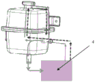
fig. 4 is a schematic view of an expansion tank provided by an embodiment of the present invention;
fig. 5 is an exploded view of an expansion tank provided in an embodiment of the present invention;
fig. 6 is a schematic diagram of a gas-liquid circulation process according to an embodiment of the present invention.
In the drawings, the reference numerals denote the following components:
1. a box body; 11. a body; 111. a first body; 112. a second body; 113. a water inlet; 114. a water outlet; 115. an installation part; 12. a neck portion; 121. an interface; 2. a water tank cover; 3. a waterproof vent valve; 4. a thermal management component.
Detailed Description
In the description of the present invention, it is to be understood that the terms "center", "longitudinal", "lateral", "length", "width", "thickness", "upper", "lower", "front", "rear", "left", "right", "vertical", "horizontal", "top", "bottom", "inner", "outer", "clockwise", "counterclockwise", "axial", "radial", "circumferential", and the like, indicate the orientation or positional relationship based on the orientation or positional relationship shown in the drawings, and are only for convenience of description and simplicity of description, and do not indicate or imply that the device or element referred to must have a particular orientation, be constructed and operated in a particular orientation, and therefore, should not be construed as limiting the present invention.
Furthermore, the terms "first", "second" and "first" are used for descriptive purposes only and are not to be construed as indicating or implying relative importance or implicitly indicating the number of technical features indicated. Thus, a feature defined as "first" or "second" may explicitly or implicitly include at least one such feature. In the description of the present invention, "a plurality" means at least two, e.g., two, three, etc., unless specifically limited otherwise.
In the present invention, unless otherwise expressly stated or limited, the terms "mounted," "connected," and "fixed" are to be construed broadly and may, for example, be fixedly connected, detachably connected, or integrally formed; can be mechanically or electrically connected; they may be directly connected or indirectly connected through intervening media, or they may be connected internally or in any other suitable relationship, unless expressly stated otherwise. The specific meaning of the above terms in the present invention can be understood according to specific situations by those of ordinary skill in the art.
In the present application, unless expressly stated or limited otherwise, the first feature may be directly on or directly under the second feature or indirectly via intermediate members. Also, a first feature "on," "over," and "above" a second feature may be directly or diagonally above the second feature, or may simply indicate that the first feature is at a higher level than the second feature. A first feature "under," "beneath," and "under" a second feature may be directly under or obliquely under the second feature, or may simply mean that the first feature is at a lesser elevation than the second feature.
In the description herein, references to the description of the term "one embodiment," "some embodiments," "an example," "a specific example," or "some examples," etc., mean that a particular feature, structure, material, or characteristic described in connection with the embodiment or example is included in at least one embodiment or example of the invention. In this specification, the schematic representations of the terms used above are not necessarily intended to refer to the same embodiment or example. Furthermore, the particular features, structures, materials, or characteristics described may be combined in any suitable manner in any one or more embodiments or examples. Furthermore, various embodiments or examples and features of different embodiments or examples described in this specification can be combined and combined by one skilled in the art without contradiction.
Referring to fig. 3-6, solid arrows in fig. 6 are liquid circulation loops, and dashed arrows are gas circulation loops. The utility model provides an expansion water tank, which comprises a tank body 1, a water tank cover 2 and a waterproof vent valve 3; the box body 1 comprises a body 11 and a neck part 12, wherein the body 11 is provided with a cavity, the neck part 12 protrudes out of the body 11, and the neck part 12 is provided with an opening and a port 121 communicated with the cavity; the tank lid 2 is connected to the neck 12 for closing the opening; the waterproof vent valve 3 is connected to the interface 121 and is configured to allow the passage of gas within the cavity.
As a further preferred embodiment, on the basis of the above-mentioned solution, the specific examples of the present invention may further include one or more of the following additions or combinations;
the mouthpiece 121 is tubular.
And/or, the tank cover 2 is provided with a pressure structure for adjusting the pressure inside the tank body 1.
And/or, the body 11 comprises a first main body 111 and a second main body 112 from top to bottom, the first main body 111 is connected to the second main body 112, and the neck 12 is arranged on the top of the first main body 111.
And/or the bottom of the second body 112 is provided with a water outlet 114; one side of the second body 112 is provided with a water inlet 113; the water inlet 113 perpendicularly intersects the axis of the water outlet 114.
And/or, the outer sides of the first body 111 and the second body 112 are each provided with at least one mounting portion 115 having a mounting hole.
And/or the mounting portions 115 on the first body 111 are staggered or opposite to the mounting portions 115 on the second body 112.
And/or the first body 111 is provided with a first flange and the second body 112 is provided with a second flange, the second flange being connected to the first flange.
And/or, the cross-sectional size of the first body 111 and the second body 112 gradually decreases from the connection of the first body 111 and the second body 112 to both sides.
And/or the cross-section of the first body 111 and the second body 112 is rectangular with rounded corners.
In a specific embodiment, the expansion water tank comprises a tank body 1, a water tank cover 2 and a waterproof ventilation valve 3; the box body 1 comprises a body 11 and a neck 12, wherein the neck 12 is provided with an opening and tubular interface 121; the water tank cover 2 is used for closing the opening; the waterproof vent valve 3 is connected to the port 121 for discharging or sucking gas from the expansion tank.
On the basis of the above-mentioned specific embodiment, the water tank cover 2 is provided with a pressure structure, and the pressure in the tank body 1 can be adjusted. The body 11 includes a first body 111 and a second body 112 from top to bottom, the first body 111 is connected to the second body 112, and the neck 12 is disposed on the top of the first body 111. The bottom of the second body 112 is provided with a water outlet 114; one side of the second body 112 is provided with a water inlet 113; the water inlet 113 perpendicularly intersects the axis of the water outlet 114. The outer sides of the first and second bodies 111 and 112 are respectively provided with a mounting portion 115 having a mounting hole, and the two mounting portions 115 are staggered with respect to the body 11.
In other embodiments, the body 11 is a combination, the first body 111 is provided with a first flange, the second body 112 is provided with a second flange, and the first body 111 and the second body 112 can be combined by the first flange and the second flange. The cross-sectional dimensions of the first body 111 and the second body 112 are gradually reduced from the connection of the first body 111 and the second body 112 to both sides. The cross-sections of the first body 111 and the second body 112 are rectangular with rounded corners.
The utility model provides a vehicle, which is provided with any one of the expansion water tank and the heat management component 4;
the heat management component 4 is communicated with the water outlet 114 and the water inlet 113, the heat management component 4, the water inlet 113, the cavity, the interface 121 and the waterproof ventilation valve 3 form a gas circulation channel, and the heat management component 4, the water inlet 113, the cavity and the water outlet 114 form a liquid loop.
Although embodiments of the present invention have been shown and described, it is understood that the above embodiments are exemplary and should not be construed as limiting the present invention, and that variations, modifications, substitutions and alterations can be made to the above embodiments by those of ordinary skill in the art without departing from the scope of the present invention.
Claims (10)
1. An expansion tank is characterized by comprising a tank body, a tank cover and a waterproof ventilation valve;
the box body comprises a body and a neck part, the body is provided with a cavity, the neck part protrudes out of the body, and the neck part is provided with an opening and a port which are communicated with the cavity;
the water tank cover is connected to the neck part for closing the opening;
the waterproof ventilation valve is connected to the interface and is set to allow the gas in the cavity to pass through.
2. The expansion tank of claim 1, wherein said mouthpiece is tubular.
3. The expansion tank as claimed in claim 1, wherein said tank cover is provided with a pressure structure for adjusting the pressure in said tank body.
4. The expansion tank as claimed in any one of claims 1 to 3, wherein the body comprises a first body and a second body from top to bottom, the first body being connected to the second body, the neck being provided at the top of the first body.
5. The expansion tank as claimed in claim 4,
a water outlet is formed in the bottom of the second main body;
a water inlet is formed in one side of the second main body;
the axis of the water inlet and the axis of the water outlet are vertically intersected.
6. The expansion tank as claimed in claim 5,
the outer sides of the first main body and the second main body are respectively provided with at least one mounting part with a mounting hole.
7. The expansion tank as claimed in claim 6,
the installation part on the first main body and the installation part on the second main body are arranged in a staggered mode or in an opposite mode.
8. Expansion tank according to claim 5,
the first body is provided with a first flange, and the second body is provided with a second flange connected to the first flange.
9. The expansion tank as claimed in claim 8,
the cross-sectional dimensions of the first body and the second body are gradually reduced from the connection part of the first body and the second body to two sides.
10. A vehicle, characterized in that the vehicle is provided with an expansion tank and a thermal management component according to any one of claims 5 to 8;
the heat management component is communicated with the water outlet and the water inlet, forms a gas circulation channel with the water inlet, the cavity, the interface and the waterproof ventilation valve, and forms a liquid loop with the water inlet, the cavity and the water outlet.
Priority Applications (1)
| Application Number | Priority Date | Filing Date | Title |
|---|---|---|---|
| CN202223055438.9U CN218816632U (en) | 2022-11-17 | 2022-11-17 | Expansion tank and vehicle |
Applications Claiming Priority (1)
| Application Number | Priority Date | Filing Date | Title |
|---|---|---|---|
| CN202223055438.9U CN218816632U (en) | 2022-11-17 | 2022-11-17 | Expansion tank and vehicle |
Publications (1)
| Publication Number | Publication Date |
|---|---|
| CN218816632U true CN218816632U (en) | 2023-04-07 |
Family
ID=87268858
Family Applications (1)
| Application Number | Title | Priority Date | Filing Date |
|---|---|---|---|
| CN202223055438.9U Active CN218816632U (en) | 2022-11-17 | 2022-11-17 | Expansion tank and vehicle |
Country Status (1)
| Country | Link |
|---|---|
| CN (1) | CN218816632U (en) |
-
2022
- 2022-11-17 CN CN202223055438.9U patent/CN218816632U/en active Active
Similar Documents
| Publication | Publication Date | Title |
|---|---|---|
| CN111446472A (en) | Integrated fuel cell system and vehicle | |
| CN115441015B (en) | Fuel cell air system and fuel cell system | |
| CN218816632U (en) | Expansion tank and vehicle | |
| JP2024503731A (en) | Expansion tanks, cooling systems, and automobiles | |
| CN101649769B (en) | Expansion water tank for automobile | |
| JP2011242098A (en) | Evaporator having cold storage function | |
| JP7753941B2 (en) | Drainage device for fuel cell, fuel cell and fuel cell system | |
| CN214477650U (en) | Integrated battery thermal management system and electric vehicle | |
| CN215863981U (en) | Water tank with expansion air bag, hydraulic center with water tank and air conditioning system with water tank | |
| CN214413294U (en) | Integrated locomotive heat management device | |
| CN113639456B (en) | Water tank with expansion air bag, hydraulic center with water tank and air conditioning system with water tank | |
| CN212339697U (en) | Oil separator, refrigerating system and air conditioner | |
| CN212227447U (en) | A liquid-gas separation device with both liquid storage and waste heat recovery functions | |
| IT201800004061A1 (en) | Air conditioning system for buses. | |
| KR101385080B1 (en) | Evaporator | |
| JP2025537390A (en) | liquid separator | |
| CN212584023U (en) | Gas cooler shell for centrifugal compressor | |
| CN210861855U (en) | Liquid storage device for compressor and compressor with same | |
| CN222457597U (en) | Air filtering overflow device and vehicle | |
| CN218287366U (en) | Integrated car thermal management device and car | |
| CN115540412A (en) | Oil separator and refrigerating system | |
| CN215596021U (en) | Constant temperature hydraulic pressure station | |
| CN113982801B (en) | Methanol filter and vehicle | |
| CN217227288U (en) | Overflow structure of auxiliary water tank | |
| CN215782452U (en) | Fuel cell system and water separator thereof |
Legal Events
| Date | Code | Title | Description |
|---|---|---|---|
| GR01 | Patent grant | ||
| GR01 | Patent grant |