CN218774353U - Mud scraping device for sewage treatment sedimentation tank - Google Patents
Mud scraping device for sewage treatment sedimentation tank Download PDFInfo
- Publication number
- CN218774353U CN218774353U CN202023244216.2U CN202023244216U CN218774353U CN 218774353 U CN218774353 U CN 218774353U CN 202023244216 U CN202023244216 U CN 202023244216U CN 218774353 U CN218774353 U CN 218774353U
- Authority
- CN
- China
- Prior art keywords
- sedimentation tank
- wall
- sewage treatment
- rod
- scraping device
- Prior art date
- Legal status (The legal status is an assumption and is not a legal conclusion. Google has not performed a legal analysis and makes no representation as to the accuracy of the status listed.)
- Active
Links
Images

Classifications
-
- Y—GENERAL TAGGING OF NEW TECHNOLOGICAL DEVELOPMENTS; GENERAL TAGGING OF CROSS-SECTIONAL TECHNOLOGIES SPANNING OVER SEVERAL SECTIONS OF THE IPC; TECHNICAL SUBJECTS COVERED BY FORMER USPC CROSS-REFERENCE ART COLLECTIONS [XRACs] AND DIGESTS
- Y02—TECHNOLOGIES OR APPLICATIONS FOR MITIGATION OR ADAPTATION AGAINST CLIMATE CHANGE
- Y02W—CLIMATE CHANGE MITIGATION TECHNOLOGIES RELATED TO WASTEWATER TREATMENT OR WASTE MANAGEMENT
- Y02W10/00—Technologies for wastewater treatment
- Y02W10/10—Biological treatment of water, waste water, or sewage
Abstract
The utility model provides a mud scraper for a sewage treatment sedimentation tank. The mud scraping device of the sewage treatment sedimentation tank comprises: precipitation of a pool; a mounting plate is arranged on the base plate, the mounting plate is fixedly mounted on the outer wall of one side of the sedimentation tank; the telescopic rod is fixedly arranged at the top of the mounting plate; the mounting block is fixedly mounted at the top end of the telescopic rod; the electric push rod is fixedly arranged at the top of the mounting block; and the hydraulic cylinder is fixedly arranged on an output shaft of the electric push rod. The utility model provides a mud scraping device of sewage treatment sedimentation tank has easy operation, and labour saving and time saving can reduce the potential safety hazard, avoids reducing sewage treatment efficiency's advantage.
Description
Technical Field
The utility model belongs to the technical field of the mud is scraped to the sedimentation tank, especially, relate to a mud device is scraped to sewage treatment sedimentation tank.
Background
The sedimentation tank is a structure for removing suspended matters in water by using sedimentation and is a device for purifying water quality, the suspended matters in water are removed by using the natural sedimentation or coagulating sedimentation of water, and the sedimentation tank is divided into a horizontal sedimentation tank and a vertical sedimentation tank according to the water flow direction. Sedimentation effect is decided on the velocity of flow of sedimentation tank normal water and the dwell time of water in the pond, in order to improve sedimentation effect, reduce the area, adopt the honeycomb pipe chute diversion sedimentation tank more, with higher speed the clarification tank, pulse clarification tank etc, sedimentation tank widely uses in waste water treatment, and sedimentation tank is at the sedimentation in-process, there is silt to produce, consequently, every interval just need scrape mud to the sedimentation tank and handle, it is when in good place to scrape mud equipment, utilize the mud scraping plate device under water to hug closely the bottom of the pool and move the mud groove of the other end from the one end of sedimentation tank, discharge mud, then wire rope will scrape the mud plate device under water and promote a take the altitude, the suitable position of the operation initiating terminal of the mud scraping plate device under water is got back to in the air, will scrape the mud plate device under water again and put down, accomplish a working stroke.
However, in the prior art, when the existing mud scraping equipment is used for scraping mud, the existing mud scraping equipment needs to be lifted for many times, so that a steel wire rope is easily broken, the underwater mud scraping plate equipment is made to fall off in water, and then maintenance personnel are needed to go to the bottom of a sedimentation tank for maintenance or replacement, so that the sewage treatment efficiency is influenced, manpower and material resources are wasted, and potential safety hazards exist.
Therefore, there is a need for a new sludge scraper for sewage treatment sedimentation tank to solve the above problems
SUMMERY OF THE UTILITY MODEL
The utility model provides a technical problem provide an easy operation, labour saving and time saving can reduce the potential safety hazard, avoids reducing sewage treatment efficiency's sewage treatment sedimentation tank mud scrapping device.
In order to solve the technical problem, the utility model provides a mud scraper for sewage treatment sedimentation tank includes: a sedimentation tank; the mounting plate is fixedly mounted on the outer wall of one side of the sedimentation tank; the telescopic rod is fixedly arranged at the top of the mounting plate; the mounting block is fixedly mounted at the top end of the telescopic rod; the electric push rod is fixedly arranged at the top of the mounting block; the hydraulic cylinder is fixedly arranged on an output shaft of the electric push rod; the fixed block is fixedly arranged on an output shaft of the hydraulic cylinder; the rotating rod is rotatably arranged on the fixed block; the two fixing plates are respectively and fixedly arranged at two ends of the rotating rod; the scraper is fixedly arranged; the two fixing plates are arranged on the outer wall of one side close to each other; the waterproof motor is fixedly arranged on the top of the fixing block; the first circular gear is fixedly sleeved on the output shaft of the waterproof motor; the second circular gear is fixedly sleeved on the rotating rod, and the first circular gear is meshed with the second circular gear; and the discharging equipment is arranged on the outer wall of one side of the sedimentation tank and is positioned below the mounting plate.
As a further scheme of the utility model, discharging equipment is including discharge gate, rectangular plate, piston, arc piece, baffle and bracing piece, the discharge gate sets up on one side outer wall of sedimentation tank, the spout has been seted up respectively to the both sides inner wall of discharge gate, rectangular plate slidable mounting is two in the spout, piston slidable mounting be in on the discharge gate, the piston with one side outer wall fixed connection of rectangular plate.
As a further aspect of the utility model, arc piece fixed mounting be in on one side outer wall of sedimentation tank, the arc piece is located the top of discharge gate, the baffle articulates on the arc piece, the baffle with one side outer wall department of meeting of sedimentation tank, four the bracing piece all sets up in the discharge gate, four the one end of bracing piece with one side outer wall fixed connection of rectangular plate, four the bracing piece is kept away from the one end of rectangular plate all with one side outer wall fixed connection of baffle.
As a further proposal of the utility model, the outer wall of one side of the baffle is provided with a slide hole, the outer wall of one side of the baffle is provided with a screw rod, one end of the screw rod extends into the slide hole and is connected with the inner wall of the slide hole in a sliding way, the outer wall of one side of the sedimentation tank is provided with a thread groove, and one end of the screw rod extends into the sliding groove and is connected with the inner wall of the sliding groove in a screwing mode.
As a further scheme of the utility model, the rotation hole has been seted up to one side outer wall of fixed block, the dwang runs through rotate the hole and with the inner wall rotation in rotation hole is connected.
As a further proposal of the utility model, the sedimentation tank is kept away from one side outer wall fixed mounting of mounting panel has the drain pipe, fixed mounting has the valve on the drain pipe.
As a further scheme of the utility model, two sliding trays have been seted up at the top of sedimentation tank, the top of sedimentation tank is equipped with concave type slide bar, the bottom of concave type slide bar extends to two respectively in the sliding tray and with two the inner wall sliding connection of sliding tray, concave type slide bar with electric putter's output shaft fixed connection.
Compared with the prior art, the utility model provides a mud scraper for sewage treatment sedimentation tank has following beneficial effect:
the utility model provides a mud device is scraped to sewage treatment sedimentation tank:
1. when mud scraping is needed, the telescopic rod, the electric push rod, the hydraulic cylinder, the fixed block, the rotating rod, the fixed plate and the scraper are mutually matched, the sedimentation tank is subjected to sludge scraping treatment;
2. when needs will scrape the mud of accomplishing and discharge, under mutually supporting through screw rod, arc piece, baffle, bracing piece, rectangular plate, spout and piston, be convenient for discharge the mud of scraping, easy operation not only like this, labour saving and time saving can reduce the potential safety hazard, avoids reducing sewage treatment efficiency's advantage.
Drawings
In order to facilitate understanding for those skilled in the art, the present invention will be further described with reference to the accompanying drawings.
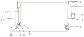
Fig. 1 is a schematic front sectional view of a mud scraper of a sewage treatment sedimentation tank according to a preferred embodiment of the present invention;
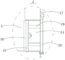
FIG. 2 is an enlarged schematic view of portion A of FIG. 1;
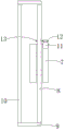
fig. 3 is an assembly view of the middle fixing block, the rotating rod, the mounting block, the scraping plate, the waterproof motor, the first circular gear and the second circular gear of the present invention;
fig. 4 is a top view of the present invention.
In the figure: 1. a sedimentation tank; 2. mounting a plate; 3. a telescopic rod; 4. mounting blocks; 5. an electric push rod; 6. a hydraulic cylinder; 7. a fixed block; 8. rotating the rod; 9. a fixing plate; 10. a squeegee; 11. a waterproof motor; 12. a first circular gear; 13. a second circular gear; 14. a discharge port; 15. a rectangular plate; 16. a piston; 17. an arc-shaped block; 18. a baffle plate; 19. a support rod.
Detailed Description
Please refer to fig. 1, fig. 2, fig. 3 and fig. 4 in combination, wherein fig. 1 is a schematic front sectional view illustrating a mud scraper of a sewage treatment sedimentation tank according to a preferred embodiment of the present invention; FIG. 2 is an enlarged schematic view of portion A of FIG. 1; fig. 3 is an assembly view of the middle fixing block, the rotating rod, the mounting block, the scraping plate, the waterproof motor, the first circular gear and the second circular gear of the present invention; fig. 4 is a top view of the present invention. The mud scraping device of the sewage treatment sedimentation tank comprises: a sedimentation tank 1; the mounting plate 2 is fixedly mounted on the outer wall of one side of the sedimentation tank 1; the telescopic rod 3 is fixedly arranged at the top of the mounting plate 2; the mounting block 4 is fixedly mounted at the top end of the telescopic rod 3; the electric push rod 5 is fixedly arranged at the top of the mounting block 4; the hydraulic cylinder 6 is fixedly arranged on an output shaft of the electric push rod 5; the fixed block 7 is fixedly arranged on an output shaft of the hydraulic cylinder 6; the rotating rod 8 is rotatably arranged on the fixed block 7; the two fixing plates 9 are respectively and fixedly arranged at two ends of the rotating rod 8; the scraper 10 is fixedly installed on the scraper 10; the two fixing plates 9 are arranged on the outer wall of one side close to each other; the waterproof motor 11 is fixedly arranged on the top of the fixing block 7; the first circular gear 12 is fixedly sleeved on an output shaft of the waterproof motor 11; the second circular gear 13 is fixedly sleeved on the rotating rod 8, and the first circular gear 12 is meshed with the second circular gear 13; the discharging device is arranged on the outer wall of one side of the sedimentation tank 1, the discharging device is positioned below the mounting plate 2.
Discharging equipment is including discharge gate 14, rectangular plate 15, piston 16, arc 17, baffle 18 and bracing piece 19, discharge gate 14 sets up on one side outer wall of sedimentation tank 1, the spout has been seted up respectively to the both sides inner wall of discharge gate 14, rectangular plate 15 slidable mounting is two in the spout, piston 16 slidable mounting is in on the discharge gate 14, piston 16 with one side outer wall fixed connection of rectangular plate 15.
The outer wall of one side of baffle 18 has seted up the slide opening, the outer wall of one side of baffle 18 is equipped with the screw rod, the one end of screw rod extend to in the slide opening and with the inner wall sliding connection of slide opening, the outer wall of one side of sedimentation tank 1 has seted up the thread groove, the one end of screw rod extend to in the spout and with the inner wall of spout closes soon and is connected.
The rotation hole has been seted up to one side outer wall of fixed block 7, dwang 8 runs through the rotation hole and with the inner wall rotation connection in rotation hole.
The sedimentation tank 1 is kept away from one side outer wall fixed mounting of mounting panel 2 has the drain pipe, fixed mounting has the valve on the drain pipe.
Two sliding grooves are formed in the top of the sedimentation tank 1, a concave sliding rod is arranged above the sedimentation tank 1, the bottom ends of the concave sliding rods extend into the two sliding grooves respectively and are connected with the inner walls of the two sliding grooves in a sliding mode, and the concave sliding rods are fixedly connected with an output shaft of the electric push rod 5.
The utility model provides a mud device is scraped to sewage treatment sedimentation tank's theory of operation as follows:
when mud scraping is needed, firstly injecting a proper amount of water into the sedimentation tank 1, stretching the telescopic rod 3 to a proper height position, starting the electric push rod 5 to perform stretching movement, closing the electric push rod 5 after the electric push rod 5 extends to a proper position, then starting the hydraulic cylinder 6 to perform stretching movement, driving the fixed block 7 to move downwards by the output shaft of the hydraulic cylinder 6, closing the hydraulic cylinder 6 after the scraper 10 is connected with the bottom of the sedimentation tank 1, starting the electric push rod 5 to perform stretching movement, and driving the scraper 10 to move through the electric push rod 5 to scrape the bottom of the sedimentation tank 1;
when the scraped mud needs to be discharged, the screw rod is rotated by hand to separate from the baffle 18, so that the baffle 18 is opened, the support rod 19 is held by hand to enable the support rod 19 to drive the rectangular plate 15 to move, so that the piston 16 is separated from the discharge hole 14, and the mud is discharged
When the scraper 10 needs to be cleaned, the same operation is carried out, the hydraulic cylinder 6 is started to shorten, the electric push rod 5 drives the scraper 10 to shorten, so that a worker can contact the scraper 10, the waterproof motor 11 is started to rotate, the waterproof motor 11 drives the first circular gear 12 to rotate, the first circular gear 12 drives the second circular gear 13 to rotate, the rotating rod 8 drives the two fixing plates 9 to rotate, the scraper 10 rotates, and the worker can clean the scraper 10 conveniently;
compared with the prior art, the utility model provides a mud scraper for sewage treatment sedimentation tank has following beneficial effect:
the utility model provides a sludge scraping device for a sewage treatment sedimentation tank, when sludge scraping is needed, the sludge scraping treatment is carried out on the sedimentation tank 1 by the mutual cooperation of a telescopic rod 3, an electric push rod 5, a hydraulic cylinder 6, a fixed block 7, a rotating rod 8, a fixed plate 9 and a scraper 10;
when needs will scrape mud that finishes and discharge, under mutually supporting through screw rod, arc piece 17, baffle 18, bracing piece 19, rectangular plate 15, spout and piston 16, be convenient for discharge scraping the mud that finishes, easy operation not only like this, labour saving and time saving can reduce the potential safety hazard, avoids reducing sewage treatment efficiency's advantage.
It should be noted that the device structure and the accompanying drawings of the present invention mainly describe the principle of the present invention, and in the design principle, the settings of the power mechanism, the power supply system, the control system, etc. of the device are not completely described, and on the premise that the skilled person understands the principle of the present invention, the details of the power mechanism, the power supply system, and the control system can be clearly known, the control mode of the application file is automatically controlled by the controller, and the control circuit of the controller can be realized by simple programming of the skilled person in the art;
the standard parts used in the method can be purchased from the market, and can be customized according to the description of the specification and the accompanying drawings, the specific connection mode of each part adopts conventional means such as mature bolts, rivets, welding and the like in the prior art, the machines, parts and equipment adopt conventional models in the prior art, and the structure and the principle of the parts known by the skilled person can be known by technical manuals or conventional experimental methods.
Although embodiments of the present invention have been shown and described, it will be appreciated by those skilled in the art that various changes, modifications, substitutions and alterations can be made herein without departing from the principles and spirit of the invention, and it is intended that in other related fields of technology, the scope of the invention be limited only by the claims and their equivalents, all of which are included within the scope of the present invention as defined in the appended claims.
Claims (7)
1. The utility model provides a mud scraping device of sewage treatment sedimentation tank which characterized in that includes:
a sedimentation tank;
the mounting plate is fixedly mounted on the outer wall of one side of the sedimentation tank;
the telescopic rod is fixedly arranged at the top of the mounting plate;
the mounting block is fixedly mounted at the top end of the telescopic rod;
the electric push rod is fixedly arranged at the top of the mounting block;
the hydraulic cylinder is fixedly arranged on an output shaft of the electric push rod;
the fixed block is fixedly arranged on an output shaft of the hydraulic cylinder;
the rotating rod is rotatably arranged on the fixed block;
the two fixing plates are respectively and fixedly arranged at two ends of the rotating rod;
the scraper is fixedly arranged; the two fixing plates are arranged on the outer wall of one side close to each other;
the waterproof motor is fixedly arranged on the top of the fixing block;
the first circular gear is fixedly sleeved on the output shaft of the waterproof motor;
the second circular gear is fixedly sleeved on the rotating rod, and the first circular gear is meshed with the second circular gear;
and the discharging equipment is arranged on the outer wall of one side of the sedimentation tank and is positioned below the mounting plate.
2. The sludge scraping device for the sewage treatment sedimentation tank according to claim 1, wherein the discharging device comprises a discharge port, a rectangular plate, a piston, an arc-shaped block, a baffle and a support rod, the discharge port is arranged on the outer wall of one side of the sedimentation tank, sliding grooves are respectively formed in the inner walls of two sides of the discharge port, the rectangular plate is slidably mounted in the two sliding grooves, the piston is slidably mounted on the discharge port, and the piston is fixedly connected with the outer wall of one side of the rectangular plate.
3. The sludge scraping device of the sewage treatment sedimentation tank of claim 2, wherein the arc-shaped block is fixedly mounted on an outer wall of one side of the sedimentation tank, the arc-shaped block is located above the discharge port, the baffle is hinged to the arc-shaped block, the baffle is connected with an outer wall of one side of the sedimentation tank, the four support rods are all arranged in the discharge port, one ends of the four support rods are fixedly connected with an outer wall of one side of the rectangular plate, and one ends of the four support rods, which are far away from the rectangular plate, are fixedly connected with an outer wall of one side of the baffle.
4. <xnotran> 2 , , , , , , . </xnotran>
5. The sludge scraping device for the sewage treatment sedimentation tank according to claim 1, wherein a rotation hole is formed in an outer wall of one side of the fixing block, and the rotation rod penetrates through the rotation hole and is rotatably connected with an inner wall of the rotation hole.
6. The sludge scraping device for the sewage treatment sedimentation tank of claim 1, wherein a drain pipe is fixedly installed on the outer wall of one side of the sedimentation tank, which is far away from the mounting plate, and a valve is fixedly installed on the drain pipe.
7. The sludge scraping device for the sewage treatment sedimentation tank according to claim 1, wherein two sliding grooves are formed in the top of the sedimentation tank, a concave sliding rod is arranged above the sedimentation tank, the bottom ends of the concave sliding rod respectively extend into the two sliding grooves and are slidably connected with the inner walls of the two sliding grooves, and the concave sliding rod is fixedly connected with the output shaft of the electric push rod.
Priority Applications (1)
| Application Number | Priority Date | Filing Date | Title |
|---|---|---|---|
| CN202023244216.2U CN218774353U (en) | 2020-12-29 | 2020-12-29 | Mud scraping device for sewage treatment sedimentation tank |
Applications Claiming Priority (1)
| Application Number | Priority Date | Filing Date | Title |
|---|---|---|---|
| CN202023244216.2U CN218774353U (en) | 2020-12-29 | 2020-12-29 | Mud scraping device for sewage treatment sedimentation tank |
Publications (1)
| Publication Number | Publication Date |
|---|---|
| CN218774353U true CN218774353U (en) | 2023-03-31 |
Family
ID=85708792
Family Applications (1)
| Application Number | Title | Priority Date | Filing Date |
|---|---|---|---|
| CN202023244216.2U Active CN218774353U (en) | 2020-12-29 | 2020-12-29 | Mud scraping device for sewage treatment sedimentation tank |
Country Status (1)
| Country | Link |
|---|---|
| CN (1) | CN218774353U (en) |
-
2020
- 2020-12-29 CN CN202023244216.2U patent/CN218774353U/en active Active
Similar Documents
| Publication | Publication Date | Title |
|---|---|---|
| CN212187967U (en) | Sewage treatment tank for sewage treatment equipment | |
| CN213856150U (en) | Circulating water tank convenient to clean | |
| CN218774353U (en) | Mud scraping device for sewage treatment sedimentation tank | |
| CN219167787U (en) | Sterilization type sedimentation tank of natural sediment | |
| CN112237785A (en) | Sludge cleaning device for sewage treatment tank | |
| CN216798956U (en) | Filtration production facility is used to medicine intermediate preparation | |
| AU2021103756A4 (en) | A Sludge Cleaning Device For Sewage Treatment Tank | |
| CN216126262U (en) | Self-cleaning sewage treatment tank | |
| CN211445092U (en) | Sewage treatment equipment | |
| CN211411104U (en) | Novel environmental protection sewage treatment device | |
| CN213610237U (en) | Novel backwashing filter | |
| CN211913015U (en) | Quick filter equipment is used in sewage treatment | |
| CN210138515U (en) | Sewage treatment plant for drainage engineering | |
| CN208288553U (en) | A kind of automatic aluminium ring cleaning vehicle | |
| CN219117205U (en) | Oil removal skimming device for sewage treatment | |
| CN220142725U (en) | Building sewage treatment device | |
| CN217511235U (en) | Self-adjusting type waste water sediment removing device capable of avoiding sediment scaling | |
| CN216890186U (en) | Air supporting sedimentation tank convenient to it is clean | |
| CN211885609U (en) | Catering sewage slag removal equipment | |
| CN218988955U (en) | Sewage sedimentation tank for water treatment | |
| CN220618489U (en) | Sewage treatment filter equipment | |
| CN220507258U (en) | Electromagnetic hot water boiler | |
| CN215692123U (en) | Sludge discharge device for sewage treatment | |
| CN213913794U (en) | A reation kettle for pipeline dredging agent production | |
| CN217650999U (en) | Sewage treatment plant for urban building |
Legal Events
| Date | Code | Title | Description |
|---|---|---|---|
| GR01 | Patent grant | ||
| GR01 | Patent grant |