CN218761663U - Pressure reducing device for vehicle - Google Patents
Pressure reducing device for vehicle Download PDFInfo
- Publication number
- CN218761663U CN218761663U CN202121587736.5U CN202121587736U CN218761663U CN 218761663 U CN218761663 U CN 218761663U CN 202121587736 U CN202121587736 U CN 202121587736U CN 218761663 U CN218761663 U CN 218761663U
- Authority
- CN
- China
- Prior art keywords
- valve
- valve seat
- valve core
- cavity shell
- core
- Prior art date
- Legal status (The legal status is an assumption and is not a legal conclusion. Google has not performed a legal analysis and makes no representation as to the accuracy of the status listed.)
- Active
Links
Images


Landscapes
- Control Of Fluid Pressure (AREA)
Abstract
The utility model relates to a vehicular pressure relief device. A pressure relief device for a vehicle, comprising: the valve seat is provided with a valve core jack; the valve cavity shell is detachably assembled with the valve seat, a valve core is assembled in the valve cavity shell in a guiding mode, the valve core is provided with an inserting section, and the inserting section is inserted into the valve core inserting hole; an inserting sealing ring is arranged between the hole wall of the valve core inserting hole and the outer peripheral surface of the inserting section of the valve core; the valve seat and the valve cavity shell can relatively translate along the axial direction of the valve core insertion hole and can be assembled in place in a relative translation mode; and a fixing structure is arranged between the valve seat and the valve cavity shell and is used for relatively fixing the valve seat and the valve cavity shell when the valve seat and the valve cavity shell are assembled in place. Above-mentioned scheme can avoid in the assembling process because relative rotation and cause cartridge sealing washer to damage.
Description
Technical Field
The utility model relates to a vehicular pressure relief device.
Background
The fluid pressure reduction device has applications in many fields, for example, in the control technology of hydrogen energy systems on board hydrogen fuel cell vehicles, the high-pressure hydrogen fluid pressure reduction device is a key component. At present, with the rapid development of the new energy automobile market, the hydrogen fuel cell automobile gradually becomes an important exploration direction for solving the energy resource crisis and the environmental crisis. However, for a hydrogen fuel cell vehicle, the pressure of the hydrogen storage system determines the amount of hydrogen stored, the current higher hydrogen storage system can reach 70Mpa, and the hydrogen input pressure required by the stack is only 1Mpa-2Mpa, so a fluid pressure reduction device needs to be arranged between the gas outlet system and the stack for pressure reduction, and the fluid pressure reduction device often includes two-stage pressure reduction valves.
A valve assembly for a gas storage system, disclosed in a patent document with publication number CN211423455U, of a fluid pressure reducing device in the prior art, includes a valve body, on which a primary pressure reducing valve and a secondary pressure reducing valve are sequentially arranged, a valve seat is arranged on the valve body, a valve core insertion hole is arranged on the valve seat, and a valve port is arranged at the bottom of the valve core insertion hole; the primary pressure reducing valve comprises a valve cavity shell for assembling a primary valve core and a primary pressure regulating spring, and the valve cavity shell is provided with external threads and is spirally connected to the valve body; the first-stage valve core is provided with an inserting section which is inserted in the valve core inserting hole; and a flow channel is arranged on the primary valve core and used for leading the hydrogen to the secondary pressure reducing valve. And a plug-in sealing ring is arranged between the hole wall of the valve core jack and the outer peripheral surface of the valve core, and the sealing ring bears the pressure of the air outlet joint.
However, hydrogen has a small molecular weight, and sealing is difficult, and particularly, sealing performance of the fluid pressure reduction device is not easily ensured under high pressure. In the fluid pressure reducing device in the prior art, when the primary pressure reducing valve is assembled on the valve body through threads, the valve seat and the valve core need to rotate relatively, so that deformation and scratch of the inserted sealing ring are easily caused, and the sealing reliability of a product is affected.
SUMMERY OF THE UTILITY MODEL
The utility model aims at providing an automobile-used pressure relief device can avoid in the assembling process because need rotate relatively between disk seat and the case and cause the cartridge sealing washer to damage.
The utility model discloses well following technical scheme of adoption:
a pressure relief device for a vehicle, comprising:
the valve seat is provided with a valve core jack;
the valve cavity shell is detachably assembled with the valve seat, a valve core is assembled in the valve cavity shell in a guiding mode, the valve core is provided with an inserting section, and the inserting section is inserted into a valve core inserting hole;
an inserting sealing ring is arranged between the hole wall of the valve core inserting hole and the outer peripheral surface of the inserting section of the valve core;
the valve seat and the valve cavity shell can relatively translate along the axial direction of the valve core insertion hole and can be assembled in place in a relative translation mode;
and a fixing structure is arranged between the valve seat and the valve cavity shell and is used for relatively fixing the valve seat and the valve cavity shell when the valve seat and the valve cavity shell are assembled in place.
Has the advantages that: by adopting the technical scheme, the valve seat and the valve cavity shell can relatively translate along the axial direction of the valve core insertion hole and can be assembled in place in a relatively translation mode, and meanwhile, the fixing structure can relatively fix the valve seat and the valve cavity shell when the valve seat and the valve cavity shell are assembled in place, so that the valve seat and the valve cavity shell cannot relatively rotate in the assembling process, and therefore the valve core insertion hole in the valve seat and the valve core arranged in the valve cavity shell cannot relatively rotate, so that deformation and scratching of the plug-in sealing ring caused by rotation are avoided, and the sealing reliability of a product is favorably ensured.
As a preferred technical scheme: the fixing structure comprises a valve seat pressing piece, the valve seat pressing piece is fixedly connected with the valve cavity shell, and the valve seat is pressed on the valve cavity shell.
Has the advantages that: adopt above-mentioned technical scheme be convenient for the independent processing of disk seat in order to improve the machining precision to be convenient for maintain.
As a preferred technical scheme: the valve seat pressing piece and/or the valve cavity shell are/is provided with flange structures, and the flange structures and fixing screws penetrating through the flange structures are fixed relatively.
Has the advantages that: the flange structure and the fixing screw are simple in structure and convenient to disassemble and assemble.
As a preferred technical scheme: the valve seat crimping piece is an air inlet connector, an air inlet channel is arranged on the air inlet connector, and the air inlet channel is communicated with the valve core jack;
and a sealing ring is arranged between the gas inlet joint and the valve seat and/or between the gas inlet joint and the valve cavity shell and is used for avoiding leakage at the gas inlet joint.
Has the advantages that: adopt above-mentioned technical scheme not need set up independent valve seat crimping spare in addition, compact structure.
As a preferred technical scheme: the air inlet channel is embedded with a filter element, the filter element is of a hollow cylindrical structure, the longitudinal section of the filter element is U-shaped, the opening of the U-shaped filter element faces the valve seat, an annular flange is arranged on the radial outer side of the opening end of the valve element, and the annular flange is supported at one end, facing the valve seat, of the air inlet joint.
Has the advantages that: above-mentioned technical scheme can utilize characteristics that disk seat and air inlet joint components of a whole that can function independently arranged to satisfy the assembly demand of cavity tube-shape filter core, the dismouting of the filter core of also being convenient for is maintained.
As a preferred technical scheme: the air inlet connector is provided with a sensor interface, the sensor interface is communicated with the air inlet channel, and the air supply pressure sensor is connected.
Has the advantages that: adopt above-mentioned technical scheme can integrate the atmospheric pressure that admits air and detect the function, compact structure.
As a preferred technical scheme: the air inlet channel penetrates through the air inlet connector along the axial direction of the valve core jack.
Has the beneficial effects that: by adopting the technical scheme, a complete linear flow channel can be formed, the complexity of the flow channel is reduced, and the flow resistance is reduced.
As a preferred technical scheme: the valve cavity shell is provided with a mounting counter bore, and the valve seat is embedded into the mounting counter bore to realize radial positioning;
the valve seat is characterized in that a boss is arranged at one end, back to the valve core, of the valve seat, an annular interval is formed between the boss and the hole wall of the mounting counter bore, an annular bulge is arranged on one side, close to the valve seat, of the valve seat pressing connection piece, and the annular bulge is embedded into the annular interval.
Has the advantages that: adopt above-mentioned technical scheme can realize the location of disk seat crimping piece, structural stability is good.
As a preferred technical scheme: the end surface of the annular protrusion is spaced from the valve seat.
Has the advantages that: adopt above-mentioned technical scheme can avoid forming the oversoluting, guarantee that the sealing washer between disk seat and the disk seat crimping spare is reliably compressed tightly, guarantees the gas tightness.
As a preferred technical scheme: the valve seat and/or the valve cavity shell are/is provided with flange structures, and the valve seat and the valve cavity shell are relatively fixed through the flange structures and fixing screws penetrating through the flange structures.
Has the advantages that: by adopting the technical scheme, the structure is simple, and the disassembly and the assembly are convenient.
Drawings
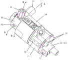
Fig. 1 is a first perspective view of an embodiment 1 of the vehicle decompression device of the present invention;
fig. 2 is a second perspective view of embodiment 1 of the vehicle pressure reducing device of the present invention;
FIG. 3 is a cross-sectional view A-A of FIG. 1;
FIG. 4 is a cross-sectional view B-B of FIG. 1;
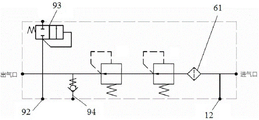
fig. 5 is a functional schematic diagram of embodiment 1 of the vehicle pressure reducing device of the present invention;
fig. 6 is a schematic structural diagram of another embodiment of the vehicle decompression device of the present invention;
names of components corresponding to corresponding reference numerals in the drawings are: 11. an air inlet joint; 12. a high pressure sensor interface; 21. a valve cavity shell; 22. a fixing hole; 23. a secondary valve seat mounting cylinder; 24. mounting a counter bore; 25. a connecting cylinder; 26. a breathing passage; 27. a breather valve; 28. a connecting channel; 31. a valve seat; 32. a boss; 33. a valve port; 41. a primary valve core; 42. a guide section; 43. a first-stage pressure regulating spring; 44. inserting a section; 45. inserting a sealing ring; 46. a primary sealing block; 47. a flow channel; 48. avoiding the mouth; 51. a valve seat crimping member; 52. an air intake passage; 53. an annular projection; 54. a flange structure; 55. a set screw; 61. a filter element; 62. an annular flange; 71. a secondary valve seat; 72. a secondary valve core; 73. a secondary pressure regulating spring; 74. a secondary sealing block; 75. a conical boss; 76. a communicating hole; 77. a Y-shaped seal ring; 78. an axial through passage; 81. an annular step; 82. pressing the valve seat; 83. a support pad; 84. a crimping sleeve; 91. an air outlet joint; 92. a low pressure sensor interface; 93. a safety valve; 94. and a service port.
Detailed Description
In order to make the objects, technical solutions and advantages of the present invention more clearly understood, the present invention will be further described in detail with reference to the accompanying drawings and embodiments. It should be understood that the specific embodiments described herein are for purposes of illustration only and are not intended to limit the invention, i.e., the described embodiments are only some, but not all embodiments of the invention. The components of embodiments of the present invention, as generally described and illustrated in the figures herein, may be arranged and designed in a wide variety of different configurations.
Thus, the following detailed description of the embodiments of the present invention, presented in the accompanying drawings, is not intended to limit the scope of the invention, as claimed, but is merely representative of selected embodiments of the invention. Based on the embodiment of the present invention, all other embodiments obtained by the person skilled in the art without creative work belong to the protection scope of the present invention.
It is noted that relational terms such as the terms first and second, and the like, may be used solely to distinguish one entity or action from another entity or action without necessarily requiring or implying any actual such relationship or order between such entities or actions. Furthermore, the terms "comprises," "comprising," or any other variation thereof, are intended to cover a non-exclusive inclusion, such that a process, method, article, or apparatus that comprises a list of elements does not include only those elements but may include other elements not expressly listed or inherent to such process, method, article, or apparatus. Without further limitation, the possible appearances of the phrases "comprising one of 8230; \8230;" defined 8230 "do not exclude the presence of additional identical elements in the processes, methods, articles, or devices that comprise the recited elements.
In the description of the present invention, unless otherwise expressly specified or limited, the terms "mounted," "connected," and "connected" when they are used are to be construed broadly, e.g., as meaning either a fixed connection, a removable connection, or an integral connection; can be mechanically or electrically connected; either directly or indirectly through intervening media, or may be interconnected between two elements. The specific meaning of the above terms in the present invention can be understood by those skilled in the art from the specific situation.
In the description of the present invention, unless otherwise explicitly specified or limited, the term "provided" may be used in a broad sense, for example, the object of "provided" may be a part of the body, or may be arranged separately from the body and connected to the body, and the connection may be a detachable connection or a non-detachable connection. The specific meaning of the above terms in the present invention can be understood by those skilled in the art from the specific situation.
The present invention will be described in further detail with reference to examples.
The utility model discloses in an automobile-used pressure relief device's embodiment 1:
the pressure reducing device for the vehicle in the embodiment is a pressure reducing device for a high-pressure hydrogen vehicle, and is used for a hydrogen energy vehicle. As shown in fig. 1 and 2, the pressure reducing device for a vehicle includes an inlet joint 11, a main valve body (i.e., a valve chamber housing 21), a pressure contact housing 84, and an outlet joint 91. The main valve body is provided with a fixing hole 22 for fixing the pressure reducing device for the vehicle; a primary pressure reducing valve and a secondary pressure reducing valve are arranged in the main valve body, and two-stage pressure reduction can be achieved. As shown in fig. 3, 4 and 5, the inlet connector 11 is provided with a high pressure sensor interface 12, and the outlet connector 91 is provided with a safety valve 93, a low pressure sensor interface 92 and a service port 94.
For the convenience of clearly describing the embodiment of the present invention, hereinafter, the end of the vehicular pressure reducing device provided with the air inlet joint 11 is used as a lower end, and the end provided with the air outlet joint 91 is used as an upper end, which is consistent with the orientation shown in fig. 3. Of course, the above "up" and "down" are not used to limit the actual placement state or usage state of the pressure reducing device for a vehicle, and the pressure reducing device for a vehicle may be horizontally arranged, obliquely arranged, or vertically arranged, and when vertically arranged, one end of the air intake joint 11 may be directed upward.
Specifically, as shown in fig. 3 and 4, the valve chamber of the primary pressure reducing valve is provided on a main valve body which forms a valve chamber housing 21 of the primary pressure reducing valve. The valve cavity of the primary pressure reducing valve is internally provided with a primary valve core 41 and a primary pressure regulating spring 43, the primary valve core 41 is arranged in an up-and-down guiding manner, the upper end of the primary valve core is supported on an annular stop step arranged on the valve cavity shell 21, and the primary pressure regulating spring 43 is used for providing acting force for the primary valve core 41 to move upwards to be far away from the valve port 33. In order to facilitate the correction of the reduced pressure, the lower end pad of the first-stage pressure regulating spring 43 is provided with a first-stage valve adjusting gasket, the thickness of the first-stage valve adjusting gasket is 0.1 or 0.2mm, and the reduced pressure is adjusted by increasing or decreasing the number of the first-stage valve adjusting gaskets. A secondary valve seat mounting cylinder 23 is arranged at the center of the top of the valve cavity shell 21 and used for assembling a secondary valve seat 71; the top of the primary valve core 41 is provided with a guide section 42, the guide section 42 is provided with a sealing ring groove, a sealing ring is arranged in the sealing ring groove, and the sealing ring enables the guide section 42 to be in sliding sealing fit with the inner wall of the secondary valve seat mounting cylinder 23.
The lower end of the valve cavity shell 21 is provided with a mounting counter bore 24, and a valve seat 31 of a primary pressure reducing valve is embedded in the mounting counter bore 24. A valve core jack is arranged on a valve seat 31 of the primary pressure reducing valve, and a valve port 33 is arranged at the bottom of the valve core jack. The lower end of the primary valve core 41 is provided with an insertion section 44, the insertion section 44 is inserted in the valve core insertion hole, and an insertion sealing ring 45 is arranged between the hole wall of the valve core insertion hole and the outer peripheral surface of the insertion section 44 of the valve core. The lower end face of the primary valve core 41 is embedded with a primary sealing block 46, and the primary sealing block 46 is used for being matched with the valve port 33 to form a certain opening degree, so that the pressure reducing effect is achieved. The inside of the first-stage valve core 41 is provided with a flow passage 47 used for leading to a second-stage pressure reducing valve of a vehicle pressure reducing device, the flow passage 47 comprises an axial passage and a radial passage, the radial passage is arranged on a small-diameter section below the plug sealing ring 45, the outer end of the radial passage is communicated with an annular gap between the first-stage valve core 41 and the wall of a valve core insertion hole, and the inner end of the radial passage is communicated with the axial passage.
The outer peripheral surface of the valve seat 31 is a smooth cylindrical surface, the outer diameter of the valve seat is matched with the inner diameter of the mounting counter bore 24 so as to realize radial positioning, and the valve seat and the valve cavity shell 21 can translate relatively along the axial direction of the valve core insertion hole and can be assembled in place in a relative translation mode; the top end face of the valve seat 31 is supported on the bottom wall of the bore in which the counterbore 24 is mounted for axial positioning. The pressure reducing device for the vehicle further comprises a valve seat crimping piece 51, the valve seat crimping piece 51 is an air inlet connector 11, an air inlet channel 52 is arranged on the air inlet connector 11, and the air inlet channel 52 penetrates through the air inlet connector 11 along the axial direction of the valve core insertion hole; the valve port 33 is located on the extending path of the intake passage 52, and the intake passage 52 is butted against the valve port 33 of the valve seat 31. One end of the valve seat 31, which faces away from the primary valve core 41, is provided with a boss 32, an annular space is formed between the boss 32 and the hole wall of the mounting counter bore 24, one side of the valve seat pressing piece 51, which is close to the valve seat 31, is provided with an annular bulge 53, and the annular bulge 53 is embedded in the annular space, so that radial positioning can be realized. The upper end surface of the air inlet joint 11 is pressed against the lower end surface of the boss 32 to fix the valve seat 31 to the valve chamber housing 21. The pressure-welding piece 51 is provided with a flange structure 54, and the flange structure 54 is provided with a screw, and can be fixed on the valve chamber shell 21 through the screw to form a fixing structure, so that the valve seat 31 and the valve chamber shell 21 are relatively fixed when being assembled in place. In order to avoid gas leakage from the interface between the inlet channel 52 and the valve port 33, a sealing ring is arranged between the inlet connector 11 and the valve seat 31, and the sealing ring is arranged in an annular groove on the lower end surface of the valve seat 31. The end face of the annular protrusion 53 is spaced from the valve seat 31, so that the compression of a sealing ring on the valve seat 31 can be ensured, and the sealing between the valve seat 31 and the air inlet joint 11 can be ensured.
The inner end of the air inlet channel 52 on the air inlet joint 11 is embedded with a filter element 61, the filter element 61 is a hollow cylindrical structure, the longitudinal section of the filter element is U-shaped, the opening of the U-shaped structure faces the valve port 33, the radial outer side of the opening end of the valve element is provided with an annular flange 62, and the annular flange 62 is supported at one end of the air inlet joint 11 facing the valve seat 31. The high pressure sensor port 12 on the air inlet joint 11 is perpendicular to the air inlet channel 52, and the inner end corresponds to the lower end of the filter element 61. The lowest end of the air inlet joint 11 is provided with external threads for connecting corresponding pipelines.
The secondary pressure reducing valve is arranged above the primary pressure reducing valve and comprises a secondary valve seat 71, a secondary valve core 72 and a secondary pressure regulating spring 73. The secondary valve seat 71 is arranged in the secondary valve seat installation cylinder 23, the lower end of the secondary valve seat 71 is supported on a supporting ring table on the inner wall of the secondary valve seat installation cylinder 23, the upper end of the secondary valve seat installation cylinder is provided with a valve seat pressing sleeve 82 and a supporting gasket 83, the valve seat pressing sleeve 82 is provided with external threads, the secondary valve seat pressing sleeve is in threaded connection with the secondary valve seat installation cylinder 23, and the secondary valve core 72 is fixed through the supporting gasket 83. A sealing ring is arranged between the valve seat pressing sleeve 82 and the inner wall of the secondary valve seat mounting cylinder 23, a secondary sealing block 74 is fixed in the middle of the secondary valve seat 71 through a screw, and a conical boss 75 is arranged on the lower side of the secondary valve core 72, so that a longer threaded hole is machined in the secondary valve seat 71 for screw assembly. The radial edge position of the secondary sealing block 74 is provided with a communicating hole 76 which is communicated up and down, and gas in a valve cavity of the primary pressure reducing valve enters the secondary pressure reducing valve. The lower end of the secondary valve core 72 is inserted in the secondary valve seat mounting cylinder 23 in a sliding sealing manner through a sealing ring arranged between the valve seat pressing sleeve 82 and the supporting gasket 83, and can be matched with the secondary sealing block 74 on the secondary valve seat 71 during up-and-down movement to form a certain opening degree, so that the pressure reduction effect is achieved. The secondary valve core 72 is provided with an axial through channel 78 which is communicated with an air outlet channel on the air outlet joint 91 along the axial direction. In order to reduce the axial dimension of the pressure reducing device and better realize light weight and miniaturization, the top of the primary valve core 41 is provided with an avoiding port 48, the avoiding port 48 is a horn mouth, and a conical boss 75 arranged on the lower side of the secondary valve core 72 is embedded into the avoiding port, so that the axial dimension is saved, the air flow drainage effect can be achieved, and the flow resistance is reduced. Of course, in other embodiments, the bypass port 48 at the top of the primary valve core 41 may be formed by a cylindrical hole, and the portion of the lower side of the secondary valve core 72 for providing the threaded hole may also be a cylindrical structure.
The low pressure sensor interface 92 and the safety valve 93 on the air outlet joint 91 are arranged perpendicular to the air outlet channel, and the air outlet joint 91 is also provided with a service port 94.
The upper part of the valve cavity shell 21 is provided with a connecting cylinder 25, the connecting cylinder 25 and the secondary valve seat mounting cylinder 23 are coaxially arranged, a secondary pressure regulating spring 73 is arranged in an annular space between the connecting cylinder 25 and the secondary valve seat mounting cylinder 23, the lower end of the secondary pressure regulating spring 73 is directly or indirectly supported on the bottom surface of the annular space, and the upper end of the secondary pressure regulating spring is supported on the secondary valve core 72 and is used for providing acting force for the secondary valve core 72 to move upwards and away from the valve port 33. In order to realize the correction of the decompression pressure, a secondary valve adjusting gasket is arranged at the lower end of the secondary pressure regulating spring 73 in a cushioning mode, the thickness of the secondary valve adjusting gasket is 0.1 mm or 0.2mm, and the decompression pressure is adjusted by increasing or decreasing the number of the secondary valve adjusting gaskets. The air outlet connector 91 is buckled at the top of the connecting cylinder 25, supported on an outer annular table at the top of the connecting cylinder 25 and forms a valve cavity of the secondary pressure reducing valve with the connecting cylinder 25. The crimping sleeve 84 is used for crimping the air outlet joint 91 onto the valve cavity shell 21, specifically, an external thread is arranged on the connecting cylinder 25 of the valve cavity shell 21, an annular step 81 is arranged at the upper end of the inner wall of the crimping sleeve 84, and the annular step 81 is used for pressing an outer annular table arranged on the outer peripheral surface of the air outlet joint 91 when the crimping sleeve 84 is in threaded connection onto the connecting cylinder 25, so that the pressing of the secondary valve core 72 is realized. Similarly, the compression of the secondary valve core 72 by the compression sleeve 84 can prevent the secondary valve core 72 from rotating during assembly, and prevent a sealing ring at an insertion section between the secondary valve core 72 and the inner wall of the valve core insertion hole or a sealing ring between the secondary valve core 72 and the air outlet joint 91 from being damaged.
As shown in fig. 4, a breathing passage 26 communicated with the valve cavity of the primary pressure reducing valve is arranged on the outer circumferential surface of the valve cavity housing 21, and a breathing valve 27 is arranged at the outer end of the breathing passage 26 for preventing the valve core from being influenced by the change of air pressure in the valve cavity when the valve core moves. The bottom surface of the annular space is provided with a connecting passage 28 communicated with the breathing passage 26, so that the valve cavity of the secondary pressure reducing valve and the valve cavity of the primary pressure reducing valve share one breathing valve 27, and the structure is compact.
During assembly, the valve core of the primary pressure reducing valve is installed in the installation counterbore 24 at the lower end of the valve cavity shell 21 in a translation mode, the valve core is supported on the bottom of the installation counterbore 24, then the air inlet joint 11 is pressed on the valve core in a translation mode, the air inlet joint 11 is fixed on the valve cavity shell 21 through the fixing screw 55, and the valve seat 31 and the valve cavity shell 21 are assembled and fixed.
When the high-pressure hydrogen gas pressure reducing valve is used, high-pressure hydrogen gas enters the valve port 33 of the primary pressure reducing valve through the gas inlet joint 11 and the filter element 61, then passes through the primary valve core 41 through the radial channel and the axial channel on the valve core, acts on the upper end surface of the primary valve core 41, pushes the primary valve core 41 to move downwards, enables the primary valve core 41 to keep balance under the combined action of the gas pressure of the upper end and the lower end of the primary valve core 41 and the primary pressure regulating spring 43, and achieves primary pressure reduction. The hydrogen after the primary pressure reduction enters the secondary valve core 72 from the communication hole 76 on the secondary valve seat 71, is discharged to the gas outlet joint 91 through the axial through channel 78 on the secondary valve core 72, acts on the upper end surface of the secondary valve core 72, pushes the secondary valve core 72 to move downwards, keeps the balance of the gas pressure of the secondary valve core 72 at the upper end and the lower end under the combined action of the secondary pressure regulating spring 73, realizes the secondary pressure reduction, and is finally discharged from the gas outlet channel on the gas outlet joint 91.
The utility model discloses embodiment 2 of well automobile-used pressure reduction device:
the present embodiment is different from embodiment 1 in that in embodiment 1, the fixing structure between the valve seat 31 and the valve chamber housing 21 includes the air inlet joint 11, and the air inlet joint 11 forms the valve seat pressing member 51, while in this embodiment, the air inlet joint 11 is disposed on the valve seat 31, which is equivalent to disposing the valve seat 31 and the air inlet joint 11 in embodiment 1 as a whole, and directly fixing the valve seat 31 and the air inlet joint 11 on the valve chamber housing 21 through the flange structure 54 on the air inlet joint 11. When the valve seat 31 is provided integrally with the air intake joint 11, the filter element 61 may be provided to be fitted from the lower end of the air intake joint 11.
The utility model discloses well automobile-used pressure reduction means's embodiment 3:
the present embodiment is different from embodiment 1 in that in embodiment 1, the air inlet joint 11 as the valve seat pressing member 51 is fixed to the valve chamber housing 21 by the flange structure 54 and the screw, whereas in this embodiment, the valve chamber housing 21 is provided with the radial fixing hole 22, and the annular protrusion 53 of the air inlet joint 11 is provided with the screw hole for the screw to pass through from the radial fixing hole 22 and fix to the annular protrusion 53, so as to fix the annular protrusion 53.
The utility model discloses well automobile-used pressure reduction means's embodiment 4:
the present embodiment is different from embodiment 1 in that, in embodiment 1, the air inlet joint 11 as the valve seat press-contact member 51 is fixed to the valve chamber housing 21 by a flange structure 54 and a fixing screw 55, whereas in the present embodiment, the valve seat press-contact member 51 is a press ring through which the air inlet joint 11 passes downward, and the press ring is fixed to the bottom end face of the valve chamber housing 21 by a screw to fix the air inlet joint 11 and the valve seat 31 to the valve seat 31.
The utility model discloses well automobile-used pressure reducing device's embodiment 5:
the difference between this embodiment and embodiment 4 is that in embodiment 4, the valve seat pressing member 51 is a pressing ring, while in this embodiment, the valve seat pressing member 51 is a pressing cap, the pressing cap is provided with an internal thread, the valve chamber housing 21 is provided with an external thread, and the pressing cap is fixed on the valve chamber housing 21 by a threaded connection and presses the valve seat 31 of the air inlet joint 11 of the valve seat 31. Of course, when the valve seat 31 and the intake joint 11 are integrally formed, the valve seat pressing member 51 may be pressed by a pressing cap.
The utility model discloses embodiment 6 of well automobile-used pressure reduction device:
the difference between this embodiment and embodiment 1 is that in embodiment 1, a boss 32 is provided at one end of the valve seat 31 facing away from the valve core, an annular space is formed between the boss 32 and the hole wall of the mounting counterbore 24, an annular protrusion 53 is provided at one side of the valve seat pressing member 51 close to the valve seat 31, and the annular protrusion 53 is embedded in the annular space, whereas in this embodiment, the outer contour of the valve seat 31 is cylindrical, and the upper end surface of the air inlet joint 11 is a plane and is directly pressed on the valve seat 31.
The utility model discloses embodiment 7 of well automobile-used pressure reducing device:
the difference between this embodiment and embodiment 1 is that in embodiment 1, a valve port 33 is provided at the bottom of a valve element insertion hole, and a primary sealing block 46 is provided on a primary valve element, but in this embodiment, the primary valve element 41 has the same flow-through mode as the secondary valve element 72, a primary sealing block is provided on the valve seat 31, an axial through channel 78 is provided on the primary valve element, the lower end opening of the axial through channel 78 corresponds to the primary sealing block, and meanwhile, a communication hole is provided on the primary sealing block for communicating an air inlet joint with the valve element insertion hole.
One end of the valve seat 31, which faces away from the valve core, is provided with a boss 32, an annular space is formed between the boss 32 and the hole wall of the mounting counterbore 24, one side of the valve seat pressing connecting piece 51, which is close to the valve seat 31, is provided with an annular bulge 53, and the annular bulge 53 is embedded in the annular space. The pressure reducing device for a vehicle in the above embodiment includes a two-stage pressure reducing valve, and in other embodiments, the pressure reducing device for a vehicle may be provided with only one stage pressure reducing structure. In addition, in the above embodiment, the secondary valve element 72 and the valve seat pressing sleeve 82 are sealed by the O-ring, in other embodiments, as shown in fig. 6, the secondary valve element 72 and the valve seat pressing sleeve 82 may be sealed by the Y-ring 77, the cross section of the Y-ring 77 is Y-shaped, and the opening faces the secondary valve seat 71, so that a linear self-sealing effect can be formed under the action of high-pressure hydrogen, which is beneficial to reducing friction force and improving the pressure reduction performance of the secondary pressure reducing valve.
The above description is only for the preferred embodiment of the present invention, and the present invention is not limited thereto, the protection scope of the present invention is defined by the claims, and all structural changes equivalent to the contents of the description and drawings of the present invention should be included in the protection scope of the present invention.
Claims (10)
1. A pressure relief device for a vehicle, comprising:
the valve seat (31), the valve core jack is arranged on the valve seat (31);
the valve cavity shell (21) is detachably assembled with the valve seat (31), a valve core is assembled in the valve cavity shell (21) in a guiding mode, the valve core is provided with an insertion section (44), and the insertion section (44) is inserted into a valve core insertion hole;
an inserting sealing ring (45) is arranged between the hole wall of the valve core inserting hole and the outer peripheral surface of an inserting section (44) of the valve core;
the valve core is characterized in that the valve seat (31) and the valve cavity shell (21) can relatively translate along the axial direction of the valve core insertion hole and can be assembled in place in a relatively translation mode;
a fixing structure is arranged between the valve seat (31) and the valve cavity shell (21) and used for fixing the valve seat (31) and the valve cavity shell (21) relatively when the valve seat is assembled in place.
2. The pressure reducing device for a vehicle as claimed in claim 1, wherein the fixing structure includes a valve seat pressing member (51), the valve seat pressing member (51) is fixedly connected to the valve chamber housing (21), and the valve seat (31) is pressed on the valve chamber housing (21).
3. The pressure reducing device for a vehicle as claimed in claim 2, wherein the valve seat pressure contact member (51) and/or the valve chamber housing (21) is provided with a flange structure (54), and is relatively fixed by the flange structure (54) and a fixing screw (55) penetrating the flange structure (54).
4. The vehicular decompression device according to claim 2 or 3, wherein the valve seat crimping member (51) is an intake connector (11), an intake passage (52) is provided on the intake connector (11), and the intake passage (52) communicates with the spool insertion hole;
and a sealing ring is arranged between the air inlet joint (11) and the valve seat (31) and/or between the air inlet joint (11) and the valve cavity shell (21) and is used for preventing gas from leaking from the air inlet joint (11).
5. The decompression device for vehicles according to claim 4, wherein a filter element (61) is embedded in the air inlet passage (52), the filter element (61) is a hollow cylindrical structure and has a U-shaped longitudinal section, the opening of the U-shaped longitudinal section faces the valve seat (31), an annular flange (62) is arranged on the radial outer side of the opening end of the valve element, and the annular flange (62) is supported at one end of the air inlet joint (11) facing the valve seat (31).
6. The decompression device for a vehicle according to claim 4, wherein a sensor port is provided on the intake joint (11), the sensor port communicating with the intake passage (52) and connected to a gas pressure sensor.
7. The decompression device for a vehicle according to claim 4, wherein the intake passage (52) penetrates the intake connector (11) in an axial direction of the spool insertion hole.
8. The pressure reducing device for the vehicle as claimed in claim 2 or 3, wherein the valve chamber shell (21) is provided with a mounting counterbore (24), and the valve seat (31) is embedded in the mounting counterbore (24) to realize radial positioning;
a boss (32) is arranged at one end, back to the valve core, of the valve seat (31), an annular space is formed between the boss (32) and the hole wall of the mounting counter bore (24), an annular protrusion (53) is arranged on one side, close to the valve seat (31), of the valve seat pressing connection piece (51), and the annular protrusion (53) is embedded into the annular space.
9. The vehicular pressure reducing device according to claim 8, characterized in that a space is provided between an end surface of the annular projection (53) and the valve seat (31).
10. The pressure reducing device for the vehicle according to claim 1, wherein a flange structure (54) is provided on the valve seat (31) and/or the valve chamber housing (21), and the valve seat (31) and the valve chamber housing (21) are relatively fixed by the flange structure (54) and a fixing screw (55) penetrating through the flange structure (54).
Priority Applications (1)
| Application Number | Priority Date | Filing Date | Title |
|---|---|---|---|
| CN202121587736.5U CN218761663U (en) | 2021-07-13 | 2021-07-13 | Pressure reducing device for vehicle |
Applications Claiming Priority (1)
| Application Number | Priority Date | Filing Date | Title |
|---|---|---|---|
| CN202121587736.5U CN218761663U (en) | 2021-07-13 | 2021-07-13 | Pressure reducing device for vehicle |
Publications (1)
| Publication Number | Publication Date |
|---|---|
| CN218761663U true CN218761663U (en) | 2023-03-28 |
Family
ID=85643476
Family Applications (1)
| Application Number | Title | Priority Date | Filing Date |
|---|---|---|---|
| CN202121587736.5U Active CN218761663U (en) | 2021-07-13 | 2021-07-13 | Pressure reducing device for vehicle |
Country Status (1)
| Country | Link |
|---|---|
| CN (1) | CN218761663U (en) |
Cited By (1)
| Publication number | Priority date | Publication date | Assignee | Title |
|---|---|---|---|---|
| CN115614490A (en) * | 2021-07-13 | 2023-01-17 | 亚普汽车部件(开封)有限公司 | Pressure reducing device for vehicle |
-
2021
- 2021-07-13 CN CN202121587736.5U patent/CN218761663U/en active Active
Cited By (1)
| Publication number | Priority date | Publication date | Assignee | Title |
|---|---|---|---|---|
| CN115614490A (en) * | 2021-07-13 | 2023-01-17 | 亚普汽车部件(开封)有限公司 | Pressure reducing device for vehicle |
Similar Documents
| Publication | Publication Date | Title |
|---|---|---|
| CN115727172B (en) | Secondary valve seat assembly structure of gas pressure reducing device | |
| US12282344B2 (en) | Gas pressure regulating device for vehicle | |
| KR20160042792A (en) | Valve device | |
| CN218761663U (en) | Pressure reducing device for vehicle | |
| CN102301299A (en) | Pressure reducing valve | |
| CN115614523B (en) | Valve core sealing plug structure of pressure reducing device for vehicle | |
| US20030151018A1 (en) | Solenoid valve | |
| CN218761661U (en) | Pressure reducing valve assembly structure of vehicle pressure reducing device | |
| CN111677924A (en) | Plug-in type pressure relief safety valve | |
| JP4226486B2 (en) | Gas regulator | |
| CN110761973B (en) | Decompression valve and compressor | |
| CN218761664U (en) | Vehicular pressure reducing valve fixing structure | |
| CN115614524A (en) | Pressure reducing valve assembling structure of vehicle pressure reducing device | |
| CN218761662U (en) | Valve core sealing and inserting structure of vehicle pressure reducing device | |
| CN218206875U (en) | Balance type gas injection valve of marine gas engine | |
| CN218761665U (en) | Vehicle pressure reducing device with breathing channel | |
| US7418973B2 (en) | Device to reduce noise in pressure regulators | |
| CN114294455B (en) | Pressure valve suitable for double-channel opening | |
| CN215334696U (en) | Low-temperature pressure increasing valve with good sealing performance | |
| CN216279581U (en) | Check valve and test equipment | |
| CN216078462U (en) | High-efficient reliable pressure retaining valve case module | |
| JP2000249001A (en) | Regulator for compressed natural gas | |
| JP2006046196A (en) | Regulator for fluid | |
| CN213393707U (en) | Valve core and pressure reducing valve | |
| JP2005227861A (en) | Pressure reducing valve |
Legal Events
| Date | Code | Title | Description |
|---|---|---|---|
| GR01 | Patent grant | ||
| GR01 | Patent grant |