CN218757497U - concrete pouring hopper - Google Patents
concrete pouring hopper Download PDFInfo
- Publication number
- CN218757497U CN218757497U CN202223139027.8U CN202223139027U CN218757497U CN 218757497 U CN218757497 U CN 218757497U CN 202223139027 U CN202223139027 U CN 202223139027U CN 218757497 U CN218757497 U CN 218757497U
- Authority
- CN
- China
- Prior art keywords
- hopper
- transmission
- eccentric
- hopper body
- concrete
- Prior art date
- Legal status (The legal status is an assumption and is not a legal conclusion. Google has not performed a legal analysis and makes no representation as to the accuracy of the status listed.)
- Active
Links
- 238000003756 stirring Methods 0.000 claims abstract description 15
- 230000005540 biological transmission Effects 0.000 claims description 57
- 229910000831 Steel Inorganic materials 0.000 claims description 20
- 239000010959 steel Substances 0.000 claims description 20
- 230000007306 turnover Effects 0.000 claims description 2
- 238000005266 casting Methods 0.000 claims 2
- 230000000694 effects Effects 0.000 abstract description 4
- 239000006185 dispersion Substances 0.000 abstract 1
- XLYOFNOQVPJJNP-UHFFFAOYSA-N water Substances O XLYOFNOQVPJJNP-UHFFFAOYSA-N 0.000 description 13
- 230000000712 assembly Effects 0.000 description 4
- 238000000429 assembly Methods 0.000 description 4
- 239000010410 layer Substances 0.000 description 2
- 238000000034 method Methods 0.000 description 2
- 230000009286 beneficial effect Effects 0.000 description 1
- 238000009435 building construction Methods 0.000 description 1
- 238000010276 construction Methods 0.000 description 1
- 230000007797 corrosion Effects 0.000 description 1
- 238000005260 corrosion Methods 0.000 description 1
- 238000010586 diagram Methods 0.000 description 1
- 238000007599 discharging Methods 0.000 description 1
- 239000000463 material Substances 0.000 description 1
- 230000004048 modification Effects 0.000 description 1
- 238000012986 modification Methods 0.000 description 1
- 238000000465 moulding Methods 0.000 description 1
- 230000000149 penetrating effect Effects 0.000 description 1
- 230000003014 reinforcing effect Effects 0.000 description 1
- 239000002002 slurry Substances 0.000 description 1
- 239000002344 surface layer Substances 0.000 description 1
Images


Landscapes
- On-Site Construction Work That Accompanies The Preparation And Application Of Concrete (AREA)
Abstract
The utility model provides a concrete placement hopper, includes hopper body and the gyro wheel of locating hopper body bottom, and hopper body bottom feed opening department is equipped with electronic unloading and turns over the board, is equipped with electronic vibrations stirring integrative device on the hopper body, and electronic vibrations stirring integrative device includes servo motor one, drive assembly and eccentric hob, and hopper body lateral wall is stretched out to eccentric hob lower part, stretches into in the post-cast strip, just, and the tip that eccentric hob stretches out is equipped with eccentric spiral leaf. This application adopts eccentric hob, can produce the vibration when dispersion stirring concrete, and the position bubble is got rid of with higher speed, and hopper end opening sets up automatically controlled board, control and opens and shuts, and the effect is pour in the speed of effective control concrete inflow, position, enhancement.
Description
Technical Field
The utility model relates to a building engineering field specifically belongs to a concrete placement hopper.
Background
In the building engineering field, the basement seepage takes place occasionally, and the percolating water not only makes underground works lose the service function, produces the spot of moulding in a large number, and can produce the corrosion to inside reinforcing bar, influences structural safety, more causes harm to personnel and each item electrical equipment, and the consuming time and power is handled in the seepage, and building construction quality and later stage dimension guarantor all can cause great influence consequently. The bottom plate post-cast strip is a high-rise leakage part of the basement, the occurrence reason is that the concrete pouring effect is poor, a cavity is formed in the lower part of the water stop steel plate, and leakage water bypasses the water stop steel plate to corrode the construction joint part of the post-cast strip. When traditional bottom plate post-cast strip was pour, used the shallow directly to empty the vibration and pour, because of directly empting on stagnant water steel sheet, the not easily controlled layering of pouring, even secondary vibration still easily produces the cavity, leads to concrete placement not closely knit.
Disclosure of Invention
The utility model aims at providing a concrete placement hopper will solve prior art and pour the instrument and pour the technical problem that the method easily produces the cavity.
In order to achieve the above purpose, the utility model adopts the following technical scheme:
the utility model provides a concrete placement hopper, includes the hopper body and locates the gyro wheel of hopper body bottom, its characterized in that: hopper body bottom feed opening department is equipped with electronic unloading and turns over the board, be equipped with electronic vibrations stirring integrated device on the hopper body, electronic vibrations stirring integrated device includes servo motor one, drive assembly and eccentric hob, the hopper body lateral wall is stretched out to eccentric hob lower part, stretches into in the post-cast strip, and, the tip that eccentric hob stretches out is equipped with eccentric spiral leaf, eccentric spiral leaf is located stagnant water steel sheet below, in the post-cast strip both sides foundation structure was located to the stagnant water steel sheet, stagnant water steel sheet curb plate is buried underground in foundation structure, and another curb plate is unsettled in the post-cast strip.
Further preferably, the transmission assembly comprises a transmission rotating shaft connected to an output end of a servo motor, and is arranged on a vertical gear in the transmission rotating shaft, and is arranged on a transverse gear in the eccentric screw rod, the transverse gear is meshed with the vertical gear to be connected, the servo motor drives the transmission rotating shaft, the vertical gear, the transverse gear and the eccentric screw rod to rotate in sequence, and then the eccentric screw blade is driven to vibrate and rotate.
Further, the hopper body is fixed with the idler wheels through the wheel carrier, a handle is further arranged on the outer wall of the hopper body, a tool box is further arranged on the outer wall of the hopper body and on the side close to the handle, an electric control switch platform used for controlling electric equipment is arranged on the handle, and a power supply used for supplying power to the electric equipment is loaded in the tool box.
Further, drive assembly and servo motor are all placed in the drive motor case in, drive motor case bottom surface still is equipped with electric lift device, electric lift device includes elevator motor, lifting telescopic handle, place the toolbox in the elevator motor, lifting telescopic handle supports in drive motor case bottom surface.
Further, the transverse gear is located inside the transmission motor box and is located at the end or the middle of the eccentric screw rod, the eccentric screw rod is connected with the transmission motor box through a bearing, and the inner ring and the outer ring of the bearing are fixedly connected with the eccentric screw rod and the bottom wall of the transmission motor box respectively.
Furthermore, the transmission rotating shaft is arranged along the length direction of the post-cast strip, at least two groups of transmission assemblies are arranged on the transmission rotating shaft, each group of transmission assemblies is in transmission connection with one eccentric screw rod, a supporting rod is further arranged between the end part, far away from the servo motor I, of the transmission rotating shaft and the transmission rotating shaft, and the transmission rotating shaft is connected with the supporting rod through a bearing.
Further, the hopper body includes 1 level hopper frame, 2 level hopper frames and 3 level hopper frames that top-down set up in order, 1 level hopper frame is the rectangle frame, 2 level hopper frame and 3 level hopper frames are four prismoid frames, and the lateral wall slope of 3 level hopper frames is less than 2 level hopper frame lateral wall slopes.
In addition, the electric blanking turning plate comprises a second servo motor, a rotating shaft and a turning plate fixed on the rotating shaft, wherein the second servo motor is fixed with the bottom wall of the hopper body through a connecting rod.
More preferably, a rubber sleeve is arranged at an outlet of the eccentric screw rod penetrating through the side wall of the 2-stage hopper frame.
Compared with the prior art the utility model has the following characteristics and beneficial effect:
the hopper body is provided with a vibration stirring device, and is used for dispersedly paving and vibrating and stirring concrete; the lifting of the vibrating stirring rod can be controlled through a button so as to avoid surface layer steel bars of the post-cast strip;
the eccentric screw rod is adopted, so that vibration can be generated while concrete is dispersedly stirred, and air bubble removal at the part is accelerated; the bottom opening of the hopper is provided with an electric control turning plate for controlling opening and closing, so that the flowing speed and position of concrete are effectively controlled, and the pouring effect is enhanced.
Drawings
FIG. 1 is a diagrammatic view of a concrete pour hopper according to the present application in use;
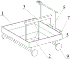
FIG. 2 is a schematic view of the structure of a hopper to which the present application relates;
fig. 3 is a schematic structural view of an electric blanking flap related to the present application;
fig. 4 is a connection diagram of the electric lifting device and the electric vibration stirring integrated device related to the application.
Detailed Description
In order to make the technical means, innovative features, objectives and functions realized by the present invention easy to understand, the present invention will be further described below.
The embodiments described herein are specific embodiments of the present invention, and are intended to be illustrative of the concepts of the present invention, which are intended to be illustrative and exemplary, and should not be construed as limiting the scope of the embodiments of the present invention. In addition to the embodiments described herein, those skilled in the art will be able to employ other technical solutions which are obvious based on the disclosure of the claims and the specification of the present application, and these technical solutions include technical solutions which make any obvious replacement or modification for the embodiments described herein.
The utility model provides a concrete pouring hopper, as shown in 1~4, including hopper body 1 with locate the gyro wheel 9 of hopper body 1 bottom, hopper body 1 bottom feed opening department is equipped with electronic unloading and turns over board 2, be equipped with integrative device 3 of electronic vibrations stirring on the hopper body 1, integrative device 3 of electronic vibrations stirring includes servo motor 31, drive assembly 32 and eccentric hob 33, the hopper body 1 lateral wall is stretched out to eccentric hob 33 lower part, stretch into in the post-cast strip 4, and, the tip that eccentric hob 33 stretches out is equipped with eccentric helical blade 34, eccentric helical blade 34 is located stagnant water steel sheet 41 below, stagnant water steel sheet 41 is located in the 4 both sides foundation structure of post-cast strip, 41 one curb plate of stagnant water steel sheet is buried underground in the foundation structure, another curb plate is unsettled in post-cast strip 4.
The transmission assembly 32 comprises a transmission rotating shaft 321 connected to the output end of the first servo motor 31, a vertical gear 322 arranged on the transmission rotating shaft 321, and a transverse gear 323 arranged on the eccentric screw rod 33, wherein the transverse gear is meshed with the vertical gear 322, and the first servo motor 31 sequentially drives the transmission rotating shaft 321, the vertical gear 322, the transverse gear 323 and the eccentric screw rod 33 to rotate, so as to drive the eccentric screw blade 34 to vibrate and rotate.
The hopper body 1 is fixed with the roller 9 through the wheel carrier 5, the handle 6 is further arranged on the outer wall of the hopper body 1, a tool box 7 is further arranged on the side close to the handle 6 on the outer wall of the hopper body 1, an electric control switch table 61 for controlling electric equipment is arranged on the handle 6, a power supply 71 for supplying power to the electric equipment is loaded in the tool box 7, the electric equipment comprises a servo motor I, a servo motor II and a lifting motor, the servo motors (the servo motor I and the servo motor II) can control lifting stirring and material discharging speed and can control concrete falling speed and falling parts to fall to the middle of a post-pouring belt water stop steel plate, concrete is stirred through eccentric rotary vibration to be uniformly paved below the post-pouring belt water stop steel plate, the eccentric spiral rod head adopts a single-side spiral to generate a vibration effect, the generation of a concrete cavity of a fan blade is reduced, the eccentric spiral rod head can be replaced, the rod head can be converted into a vibration rod for concrete paving, part of the eccentric spiral rod head can also be replaced into a vibration rod, the vibration rod is independently connected with the motor to vibrate.
The transverse gear 323 is located inside the transmission motor box 35 and at the end of the eccentric screw rod 33, the eccentric screw rod 33 is connected with the transmission motor box 35 through a bearing, and the inner ring and the outer ring of the bearing are fixedly connected with the bottom wall of the eccentric screw rod 33 and the transmission motor box 35 respectively.
The transmission rotating shaft 321 is arranged along the length direction of the post-cast strip 4, at least two groups of transmission assemblies 32 are arranged on the transmission rotating shaft 321, each group of transmission assemblies 32 is in transmission connection with one eccentric screw rod 33, a supporting rod 324 is further arranged between the end part of the transmission rotating shaft 321, which is far away from the servo motor I31, of the transmission rotating shaft 321 and the transmission rotating shaft 321, and the transmission rotating shaft 321 is connected with the supporting rod 324 through a bearing.
The electric blanking turning plate 2 comprises a second servo motor 21, a rotating shaft 22 and a turning plate 23 fixed on the rotating shaft 22, and the second servo motor 21 is fixed with the bottom wall of the hopper body 1 through a connecting rod 24.
The outlet of the eccentric screw rod 33 passing through the side wall of the 2-stage hopper frame 12 is provided with a rubber sleeve for preventing slurry leakage.
A pouring method of a concrete pouring hopper comprises the following steps:
the feed opening of the hopper body 1 is located right above the post-cast strip 4, the electric control switch board 61 controls the electric blanking turning plate 2 to turn over for blanking, the electric lifting device 8 controls the transmission motor box 35 to move downwards, then the eccentric spiral rod 33 is controlled to avoid a steel bar layer above the post-cast strip 4 and stretch into the position below the water-stop steel plate 41, through vibration stirring, concrete vibrates towards the position below the water-stop steel plate 41 of the post-cast strip, after the concrete is basically paved below the water-stop steel plate, the transmission motor box 35 controls the transmission motor box 35 to move upwards, namely the eccentric spiral rod 33 is folded, the hopper body 1 is pushed to the next pouring point to be paved, pouring is carried out, and after the concrete in the post-cast strip is all poured to the position 41 of the water-stop steel plate, the next layer of post-cast strip can be poured.
The utility model discloses the part that does not relate to all is the same with prior art or can adopt prior art to realize.
The basic principles and the main features of the invention and the advantages of the invention have been shown and described above, it will be evident to those skilled in the art that the invention is not limited to the details of the foregoing illustrative embodiments, but that the invention may be embodied in other specific forms without departing from the spirit or essential characteristics of the invention. The present embodiments are therefore to be considered in all respects as illustrative and not restrictive, the scope of the invention being indicated by the appended claims rather than by the foregoing description, and all changes which come within the meaning and range of equivalency of the claims are therefore intended to be embraced therein. Any reference sign in a claim should not be construed as limiting the claim concerned.
Furthermore, it should be understood that although the present specification describes embodiments, not every embodiment includes only a single embodiment, and such description is for clarity purposes only, and it is to be understood that all embodiments may be combined as appropriate by one of ordinary skill in the art to form other embodiments as will be apparent to those of skill in the art from the description herein.
Claims (6)
1. The utility model provides a concrete placement hopper, includes hopper body (1) and locates gyro wheel (9) of hopper body (1) bottom, its characterized in that: an electric blanking turnover plate (2) is arranged at a blanking opening at the bottom of the hopper body (1), an electric vibration and stirring integrated device (3) is arranged on the hopper body (1), the electric vibration and stirring integrated device (3) comprises a servo motor I (31), a transmission assembly (32) and an eccentric screw rod (33), the lower part of the eccentric screw rod (33) extends out of the side wall of the hopper body (1) and extends into the post-pouring belt (4), an eccentric screw blade (34) is arranged at the extending end part of the eccentric screw rod (33), the eccentric screw blade (34) is positioned below a water-stopping steel plate (41), the water-stopping steel plate (41) is arranged in foundation structures at two sides of the post-pouring belt (4), one side plate of the water-stopping steel plate (41) is embedded in the foundation structure, and the other side plate is suspended in the post-pouring belt (4); transmission subassembly (32) are including connecting in transmission pivot (321) of servo motor (31) output, locate vertical gear (322) on transmission pivot (321) are located horizontal gear (323) on eccentric hob (33), horizontal gear and vertical gear (322) meshing are connected, servo motor (31) drive transmission pivot (321), vertical gear (322), horizontal gear (323), eccentric hob (33) rotation in order, then drive eccentric spiral leaf (34) vibration rotation.
2. A concrete casting hopper according to claim 1, wherein: hopper body (1) is fixed with gyro wheel (9) through wheel carrier (5), still be equipped with handle (6) on hopper body (1) outer wall, be close to handle (6) side and still be equipped with toolbox (7), be equipped with on handle (6) and be used for controlling electric equipment's automatically controlled switch board (61), power (71) for the electric equipment power supply are loaded in toolbox (7).
3. A concrete pouring hopper according to claim 2, wherein: transmission motor case (35) is all placed in transmission assembly (32) and servo motor (31), transmission motor case (35) bottom surface still is equipped with electric lift device (8), electric lift device (8) include elevator motor (81), lifting telescopic link (82), place in toolbox (7) in elevator motor (81), lifting telescopic link (82) support in transmission motor case (35) bottom surface.
4. A concrete pouring hopper according to claim 3, wherein: the transverse gear (323) is located inside the transmission motor box (35) and located at the end of the eccentric spiral rod (33), the eccentric spiral rod (33) is connected with the transmission motor box (35) through a bearing, and the inner ring and the outer ring of the bearing are fixedly connected with the bottom wall of the eccentric spiral rod (33) and the bottom wall of the transmission motor box (35) respectively.
5. A concrete pouring hopper according to claim 2, wherein: the length direction of post-cast strip (4) is followed in transmission pivot (321) sets up, is equipped with at least two sets of drive assembly (32) on transmission pivot (321), and every drive assembly (32) of group links to each other with an eccentric hob (33) transmission, and still be equipped with branch (324) between tip, transmission pivot (321) and the transmission pivot (321) of servo motor (31) are kept away from in transmission pivot (321), transmission pivot (321) are connected through the bearing with branch (324).
6. A concrete casting hopper according to claim 1, wherein: hopper body (1) includes 1 level hopper frame (11), 2 level hopper frame (12) and 3 level hopper frame (13) that top-down set up in order, 1 level hopper frame (11) are the rectangle frame, 2 level hopper frame (12) and 3 level hopper frame (13) are four prismatic table shape frames, and the lateral wall slope of 3 level hopper frame (13) is less than 2 level hopper frame (12) lateral wall slope.
Priority Applications (1)
| Application Number | Priority Date | Filing Date | Title |
|---|---|---|---|
| CN202223139027.8U CN218757497U (en) | 2022-11-25 | 2022-11-25 | concrete pouring hopper |
Applications Claiming Priority (1)
| Application Number | Priority Date | Filing Date | Title |
|---|---|---|---|
| CN202223139027.8U CN218757497U (en) | 2022-11-25 | 2022-11-25 | concrete pouring hopper |
Publications (1)
| Publication Number | Publication Date |
|---|---|
| CN218757497U true CN218757497U (en) | 2023-03-28 |
Family
ID=85675215
Family Applications (1)
| Application Number | Title | Priority Date | Filing Date |
|---|---|---|---|
| CN202223139027.8U Active CN218757497U (en) | 2022-11-25 | 2022-11-25 | concrete pouring hopper |
Country Status (1)
| Country | Link |
|---|---|
| CN (1) | CN218757497U (en) |
Cited By (1)
| Publication number | Priority date | Publication date | Assignee | Title |
|---|---|---|---|---|
| CN115627800A (en) * | 2022-11-25 | 2023-01-20 | 中国建筑第二工程局有限公司 | Vibration and stirring integrated hopper suitable for post-cast strip construction and pouring method thereof |
-
2022
- 2022-11-25 CN CN202223139027.8U patent/CN218757497U/en active Active
Cited By (1)
| Publication number | Priority date | Publication date | Assignee | Title |
|---|---|---|---|---|
| CN115627800A (en) * | 2022-11-25 | 2023-01-20 | 中国建筑第二工程局有限公司 | Vibration and stirring integrated hopper suitable for post-cast strip construction and pouring method thereof |
Similar Documents
| Publication | Publication Date | Title |
|---|---|---|
| CN111590749B (en) | Vertical vibration forming process and forming equipment for reinforced concrete pipe | |
| CN107175022A (en) | A kind of road and bridge construction raw material blending device | |
| CN109624042B (en) | Prestressed pipe pile production system | |
| CN218757497U (en) | concrete pouring hopper | |
| CN106079086A (en) | A kind of mixed earth stirrer being easy to feeding and blanking | |
| CN107649615A (en) | Building bar straightening and abscinding and derusting device | |
| CN109773952A (en) | A kind of short-term matching segment beam circulation flow production line and its production method | |
| CN214738086U (en) | High efficiency construction equipment for building bridge pile foundation concrete | |
| CN107916612A (en) | A kind of multifunction road prosthetic device | |
| CN210194437U (en) | High efficiency bridge concrete's equipment of pouring | |
| CN217257265U (en) | Concrete filling device | |
| CN116480152A (en) | Concrete pouring device for house construction engineering and use method | |
| CN115627800A (en) | Vibration and stirring integrated hopper suitable for post-cast strip construction and pouring method thereof | |
| CN214462648U (en) | Multifunctional concrete pouring hopper for building construction | |
| CN206605635U (en) | A kind of mixer | |
| CN206568331U (en) | Road and bridge construction concrete special agitating device | |
| CN206815147U (en) | A kind of cement floor file machine | |
| CN207562964U (en) | Buffer-type construction crushing lifting device | |
| CN205348187U (en) | Feeding device of cloth machine | |
| CN117301286B (en) | Reinforcement cage concrete grouting device for green construction | |
| CN206487150U (en) | A kind of flat vibrator | |
| CN111501488A (en) | Concrete vibrating device for municipal highway engineering | |
| CN216782244U (en) | Mixing arrangement that concrete aggregate was used | |
| CN210854436U (en) | Environment-friendly material storage device for concrete | |
| CN215557447U (en) | Concrete unloading is with preventing splash cleaning device |
Legal Events
| Date | Code | Title | Description |
|---|---|---|---|
| GR01 | Patent grant | ||
| GR01 | Patent grant |