CN218745869U - Special welding jig of intelligence wrist-watch PCBA board - Google Patents
Special welding jig of intelligence wrist-watch PCBA board Download PDFInfo
- Publication number
- CN218745869U CN218745869U CN202223218357.6U CN202223218357U CN218745869U CN 218745869 U CN218745869 U CN 218745869U CN 202223218357 U CN202223218357 U CN 202223218357U CN 218745869 U CN218745869 U CN 218745869U
- Authority
- CN
- China
- Prior art keywords
- fixed
- anchor clamps
- pcba board
- watch
- arc
- Prior art date
- Legal status (The legal status is an assumption and is not a legal conclusion. Google has not performed a legal analysis and makes no representation as to the accuracy of the status listed.)
- Active
Links
Images

Landscapes
- Butt Welding And Welding Of Specific Article (AREA)
Abstract
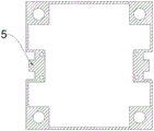
The utility model discloses a special welding jig of intelligence wrist-watch PCBA board, which comprises a fixture, four end feet of anchor clamps up end are all fixed and are equipped with the locating lever, the top of anchor clamps is equipped with the clamp plate, the constant head tank has all been seted up to four end feet of clamp plate, four the locating lever is all gone into four in the constant head tank, the inside of anchor clamps is equipped with the slot, the inside both sides of slot all are equipped with fixed arc piece, two fixed arc piece with be equipped with the loose axle between the anchor clamps, fixed arc piece with anchor clamps pass through loose axle swing joint, fixed arc piece with be equipped with spring A between the anchor clamps inner wall, the inside both sides of slot all are equipped with the fixed plate, the fixed elastic rod that is equipped with in one side of fixed plate, the outside cover of elastic rod is equipped with spring B, the top of clamp plate is equipped with fixed briquetting. The utility model discloses a novel anchor clamps strengthen the stability of centre gripping, improve work efficiency.
Description
Technical Field
The utility model relates to a special welding jig technical field of wrist-watch PCBA board specifically is a special welding jig of intelligence wrist-watch PCBA board.
Background
With the rapid development of social economy, the PCBA refers to a finished product which is made by assembling a PCB board through SMT mounting, DIP plugging, testing and the like, and we can understand that the PCB board is a finished circuit board.
When the welding fixture is used for welding, the fixture is required to be fixed for welding, and the accuracy and the stability of welding are ensured.
However, the conventional clamp cannot well clamp the PCBA, so that the working efficiency is reduced; therefore, the existing requirements are not met, and the special welding fixture for the PCBA board of the intelligent watch is provided for the requirements.
SUMMERY OF THE UTILITY MODEL
An object of the utility model is to provide a special welding jig of intelligence wrist-watch PCBA board to current anchor clamps that provide in solving above-mentioned background art can not be fine carry out the centre gripping to the PCBA board, have reduced work efficiency scheduling problem.
In order to achieve the above object, the utility model provides a following technical scheme: the utility model provides a special welding jig of intelligence wrist-watch PCBA board, includes anchor clamps, four end feet of anchor clamps up end are all fixed and are equipped with the locating lever, the top of anchor clamps is equipped with the clamp plate, the constant head tank has all been seted up to four end feet of clamp plate, four the locating lever is all gone into four in the constant head tank, the inside of anchor clamps is equipped with the slot, the inside both sides of slot all are equipped with fixed arc piece, two fixed arc piece with be equipped with the loose axle between the anchor clamps, fixed arc piece with anchor clamps pass through loose axle swing joint, fixed arc piece with be equipped with spring A between the anchor clamps inner wall, the inside both sides of slot all are equipped with the fixed plate, one side of fixed plate is fixed and is equipped with the elastic rod, the outside cover of elastic rod is equipped with spring B, the top of clamp plate is equipped with fixed briquetting, the below of fixed briquetting is equipped with the arc inserted bar, the arc inserted bar inserts in the slot, the inside both sides of arc inserted bar all are equipped with the arc wall, fixed arc piece card is gone into in the arc wall.
Preferably, the inside of anchor clamps is equipped with the resettlement groove, the PCBA integrated circuit board income the resettlement inslot for the fixed of PCBA board.
Preferably, the both sides of clamp plate have all been seted up concave groove, fixed briquetting card is gone into in the concave groove, plays the fixed action of location.
Preferably, the fixing plate is made of rubber, and the arc-shaped inserting rod is reinforced to be fixed.
Preferably, four end feet of the clamp are provided with anti-collision pads, so that an anti-collision effect is achieved.
Preferably, four terminal surfaces of clamp plate all are equipped with the extension piece, strengthen the centre gripping fixed to PCBA board.
Compared with the prior art, the beneficial effects of the utility model are that:
1. the utility model discloses a place the PCBA board in the middle of anchor clamps, press the top at the PCBA board through the clamp plate, then the locating lever of four end feet of anchor clamps up end is aimed at through the constant head tank that four end feet of clamp plate were seted up with its card income, then just push down the PCBA board, aim at the inside slot of clamp plate with the fixed briquetting that has the arc inserted bar again and insert it, after inserting then the fixed arc piece of the inside both sides of slot can be pressed to both sides under the pressure of arc inserted bar, then fixed arc piece removes to both sides under the drive of loose axle simultaneously, then fixed arc piece carries out compression motion with the inside spring A of anchor clamps simultaneously, then just fixed arc piece reachs the inside arc wall in arc inserted bar both sides after the arc inserted bar inserts the slot is inside completely, then compressed spring A pops out simultaneously, go into arc wall inside alright fix it with fixed arc piece card.
Drawings
Fig. 1 is a schematic overall structure diagram of the present invention;
FIG. 2 is a schematic structural view of the pressing plate of the present invention;
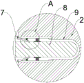
fig. 3 is a schematic view of a partial structure of the plug-in structure of the present invention;
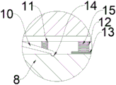
fig. 4 is a schematic diagram of a local enlarged structure of the insertion structure a of the present invention.
In the figure: 1. PCBA board; 2. a clamp; 3. positioning a groove; 4. positioning a rod; 5. pressing a plate; 6. fixing the pressing block; 7. a movable shaft; 8. an arc-shaped inserted link; 9. a slot; 10. fixing the arc-shaped block; 11. a spring A; 12. a spring B; 13. a fixing plate; 14. an arc-shaped slot; 15. an elastic rod.
Detailed Description
The technical solutions in the embodiments of the present invention will be described clearly and completely with reference to the accompanying drawings in the embodiments of the present invention, and it is obvious that the described embodiments are only some embodiments of the present invention, not all embodiments.
Referring to fig. 1 to 4, the present invention provides an embodiment of: the utility model provides a special welding jig of intelligence wrist-watch PCBA board, including anchor clamps 2, four end feet of 2 up end of anchor clamps are all fixed and are equipped with locating lever 4, anchor clamps 2's top is equipped with clamp plate 5, constant head tank 3 has all been seted up to four end feet of clamp plate 5, four locating lever 4 all block into in four constant head tank 3, anchor clamps 2's inside is equipped with slot 9, slot 9 inside both sides all are equipped with fixed arc piece 10, be equipped with loose axle 7 between two fixed arc pieces 10 and anchor clamps 2, fixed arc piece 10 passes through loose axle 7 swing joint with anchor clamps 2, be equipped with spring A11 between fixed arc piece 10 and the anchor clamps 2 inner wall, slot 9 inside both sides all are equipped with fixed plate 13, the fixed elastic rod 15 that is equipped with in one side of fixed plate 13, the outside cover of elastic rod 15 is equipped with spring B12, clamp plate 5's top is equipped with fixed briquetting 6, the arc inserted bar 8 of fixed briquetting 6 below, arc inserted bar 8 inserts in slot 9, the inside both sides of arc inserted bar 8 all are equipped with fixed arc piece 10 card goes into in fixed arc piece 14, through PCBA board 1 in the middle of placing PCBA board 1, the clamp plate 5 the end feet of clamp plate 3, it is just to push down the end feet of four locating lever 1.
Further, the inside of anchor clamps 2 is equipped with the resettlement groove, and PCBA board 1 card is gone into the resettlement inslot for PCBA board 1's is fixed.
Furthermore, the two sides of the pressing plate 5 are provided with concave grooves, and the fixed pressing block 6 is clamped into the concave grooves to fix the position.
Further, the fixing plate 13 is made of rubber, and the fixing of the arc-shaped inserting rod 8 is strengthened.
Further, four end feet of the clamp 2 are provided with anti-collision pads, so that an anti-collision effect is achieved.
Further, four terminal surfaces of clamp plate 5 all are equipped with the extension piece, strengthen the centre gripping fixed to PCBA board 1.
The working principle is as follows: during the use, the slot 9 that the fixed briquetting 6 that will have arc inserted bar 8 aligns 5 inside of clamp plate again inserts it, after inserting then the fixed arc piece 10 of the inside both sides of slot 9 can be pushed to both sides under the pressure of arc inserted bar 8, then fixed arc piece 10 moves to both sides under the drive of loose axle 7 simultaneously, then fixed arc piece 10 carries out compression motion with the inside spring A11 of anchor clamps 2 simultaneously, then just fixed arc piece 10 reachs the inside arc wall 14 of arc inserted bar 8 both sides after arc inserted bar 8 inserts slot 9 inside completely, then compressed spring A11 pops out simultaneously, go into fixed arc piece 10 card inside alright fix it to arc wall 14.
It is obvious to a person skilled in the art that the invention is not restricted to details of the above-described exemplary embodiments, but that it can be implemented in other specific forms without departing from the spirit or essential characteristics of the invention. The present embodiments are therefore to be considered in all respects as illustrative and not restrictive, the scope of the invention being indicated by the appended claims rather than by the foregoing description, and all changes which come within the meaning and range of equivalency of the claims are therefore intended to be embraced therein. Any reference sign in a claim should not be construed as limiting the claim concerned.
Claims (6)
1. The utility model provides a special welding jig of intelligence wrist-watch PCBA board, includes anchor clamps (2), its characterized in that: four end feet of the upper end surface of the clamp (2) are fixedly provided with positioning rods (4), a pressing plate (5) is arranged above the clamp (2), the four end feet of the pressing plate (5) are respectively provided with a positioning groove (3), the four positioning rods (4) are respectively clamped into the four positioning grooves (3), a slot (9) is arranged inside the clamp (2), two sides inside the slot (9) are respectively provided with a fixed arc-shaped block (10), two fixed arc-shaped blocks (10) are arranged between the fixed arc-shaped blocks (10) and the clamp (2) and are respectively provided with a movable shaft (7), the fixed arc-shaped blocks (10) are movably connected with the clamp (2) through the movable shafts (7), a spring B (12) is sleeved outside the elastic rods (15), a fixed pressing block (6) is arranged above the pressing plate (5), two sides inside the slot (9) are respectively provided with a fixed plate (13), one side of each fixed plate (13) is fixedly provided with an elastic rod (15), two sides of each elastic rod (15) are respectively provided with an arc-shaped block (8), two inserting grooves (8) are respectively arranged below the arc-shaped block (8), the fixed arc-shaped block (10) is clamped in the arc-shaped groove (14).
2. The special welding jig of intelligence wrist-watch PCBA board of claim 1, characterized in that: the inside of anchor clamps (2) is equipped with the resettlement groove, PCBA board (1) card is gone into in the resettlement groove.
3. The special welding jig of intelligence wrist-watch PCBA board of claim 1, characterized in that: the two sides of the pressing plate (5) are provided with concave grooves, and the fixed pressing block (6) is clamped in the concave grooves.
4. The special welding jig of intelligence wrist-watch PCBA board of claim 1, characterized in that: the fixing plate (13) is made of rubber.
5. The special welding jig of intelligence wrist-watch PCBA board of claim 1, characterized in that: four end feet of the clamp (2) are provided with anti-collision pads.
6. The special welding jig of intelligence wrist-watch PCBA board of claim 1, characterized in that: four end faces of the pressing plate (5) are provided with extension blocks.
Priority Applications (1)
| Application Number | Priority Date | Filing Date | Title |
|---|---|---|---|
| CN202223218357.6U CN218745869U (en) | 2022-12-02 | 2022-12-02 | Special welding jig of intelligence wrist-watch PCBA board |
Applications Claiming Priority (1)
| Application Number | Priority Date | Filing Date | Title |
|---|---|---|---|
| CN202223218357.6U CN218745869U (en) | 2022-12-02 | 2022-12-02 | Special welding jig of intelligence wrist-watch PCBA board |
Publications (1)
| Publication Number | Publication Date |
|---|---|
| CN218745869U true CN218745869U (en) | 2023-03-28 |
Family
ID=85677145
Family Applications (1)
| Application Number | Title | Priority Date | Filing Date |
|---|---|---|---|
| CN202223218357.6U Active CN218745869U (en) | 2022-12-02 | 2022-12-02 | Special welding jig of intelligence wrist-watch PCBA board |
Country Status (1)
| Country | Link |
|---|---|
| CN (1) | CN218745869U (en) |
-
2022
- 2022-12-02 CN CN202223218357.6U patent/CN218745869U/en active Active
Similar Documents
| Publication | Publication Date | Title |
|---|---|---|
| CN203062146U (en) | Automobile welding fixture | |
| CN218745869U (en) | Special welding jig of intelligence wrist-watch PCBA board | |
| CN104015033B (en) | Bulb press-loading device | |
| CN207942109U (en) | Protection board is welded and fixed fixture and lithium battery protection board welder | |
| CN207656499U (en) | A kind of non-ferrous metals processing fixing device | |
| CN208696713U (en) | A kind of water-air intercooler main board press mounting tooling | |
| CN203734926U (en) | Chip rapid pressing device | |
| CN218272872U (en) | Auxiliary jig for positioning and welding camera module lens | |
| CN209681154U (en) | A kind of neodymium iron boron magnetic body production magnetic field forming press sampler | |
| CN204747997U (en) | Full -automatic location compresses tightly pressurize carrier | |
| CN208094927U (en) | A kind of packaging system of flexible PCB | |
| CN211193783U (en) | Clamping workbench for machining mechanical parts | |
| CN103346452B (en) | SOP to DIP conversion chip carrier socket | |
| CN221049242U (en) | Stainless steel watchcase pad printing presses stabilising arrangement | |
| CN203076821U (en) | Transverse shock absorber base assembling tool | |
| CN203433989U (en) | Three-frame three-column amorphous alloy iron core forming platform | |
| CN208555857U (en) | A kind of automatic riveter of water pump | |
| CN208437913U (en) | Internal handle pivot pin is pushed into mechanism | |
| CN105598886B (en) | Detent mechanism | |
| CN216505100U (en) | High efficiency plug-in components robot is stabilized in centre gripping | |
| CN208933397U (en) | A kind of cladding processing modularization installation frame | |
| CN216370670U (en) | Laser welding shell fragment tool | |
| CN212033408U (en) | Automatic assembly riveting tail clamp machine for USB single shielding shell | |
| CN216670060U (en) | Stable transmission module of heavy current | |
| CN107662078A (en) | A kind of cable welding of electric connector fixture |
Legal Events
| Date | Code | Title | Description |
|---|---|---|---|
| GR01 | Patent grant | ||
| GR01 | Patent grant |