CN218741421U - Hydrolysis medicament mixing arrangement - Google Patents
Hydrolysis medicament mixing arrangement Download PDFInfo
- Publication number
- CN218741421U CN218741421U CN202222242970.5U CN202222242970U CN218741421U CN 218741421 U CN218741421 U CN 218741421U CN 202222242970 U CN202222242970 U CN 202222242970U CN 218741421 U CN218741421 U CN 218741421U
- Authority
- CN
- China
- Prior art keywords
- tank body
- wall
- stirring shaft
- jar
- perforated pipe
- Prior art date
- Legal status (The legal status is an assumption and is not a legal conclusion. Google has not performed a legal analysis and makes no representation as to the accuracy of the status listed.)
- Active
Links
Images
Abstract
The utility model provides a medicament mixing arrangement hydrolysises, it can make material misce bene and greatly reduced discharging pipe block up and the emergence of jar wall scale deposit, has improved production efficiency, and it includes a jar body, the upper portion of jar body is provided with feed inlet, lower part and is provided with discharge gate, its characterized in that: a stirring motor is further fixed above the top of the tank body and is connected with a stirring shaft through a speed reducer, the stirring shaft extends downwards to the inside of the tank body, a first blade is mounted at the bottom of the stirring shaft and is close to the bottom of the inner wall of the tank body, a plurality of second blades are further mounted on the stirring shaft, and the top end of each second blade is close to the inner side wall of the tank body; the upper part of the tank body is also provided with a water inlet which is connected with a perforated pipe, and the perforated pipe is fixed on the upper part of the inner wall of the tank body in a surrounding manner; and a right-angle elbow discharging pipe is arranged on the discharging port.
Description
Technical Field
The utility model relates to a relevant technical field of chemical industry equipment, concretely relates to medicament mixing arrangement hydrolysises.
Background
At present, the hot alkali hydrolysis medicament is commonly used as calcium oxide powder, and the common addition mode is as follows: the calcium oxide and water are mixed to form lime emulsion, and then the lime emulsion is pumped into a batching kettle to be mixed with sludge and then subjected to thermal alkali hydrolysis treatment. In practical production application, the problems of uneven medicament mixing, blockage of a discharge pipeline, scaling on the wall of a medicament tank and the like often occur, and due to the property of lime, the formed scale has thick and hard characteristics. The hydrolysis effect of the sludge at the rear end can be influenced by uneven mixing of the agents; performing acid treatment after wall drilling and polishing on the tank wall for scaling; the pipeline blockage is manually cleaned because the conveying pipeline is thin; the problems mentioned above often occur and once they occur, production is suspended for cleaning, which can seriously affect production efficiency and thus enterprise efficiency.
SUMMERY OF THE UTILITY MODEL
In order to solve the problems mentioned in the above, the present invention provides a hydrolysis reagent mixing device, which can uniformly mix materials and greatly reduce the occurrence of blockage of a discharging pipe and scaling of a tank wall, thereby improving the production efficiency.
The technical scheme is as follows:
the utility model provides a medicament mixing arrangement hydrolysises, its includes a jar body, the upper portion of jar body is provided with the feed inlet, the lower part is provided with discharge gate, its characterized in that: a stirring motor is further fixed above the top of the tank body and is connected with a stirring shaft through a speed reducer, the stirring shaft extends downwards to the inside of the tank body, a first paddle is mounted at the bottom of the stirring shaft and is close to the bottom of the inner wall of the tank body, a plurality of second paddles are further mounted on the stirring shaft, and the top end of each second paddle is close to the inner side wall of the tank body; the upper part of the tank body is also provided with a water inlet which is connected with a perforated pipe, and the perforated pipe is fixed on the upper part of the inner wall of the tank body in a surrounding manner; and a right-angle elbow discharging pipe is arranged on the discharging port.
Furthermore, the shape of the first paddle is matched with the shape of the bottom of the inner wall of the tank body.
Further, the upper portion of the tank body is also provided with an exhaust hole and a manhole, and the bottom of the tank body is also provided with a sewage draining outlet.
Furthermore, a support is arranged at the top of the tank body, and the stirring motor and the speed reducer are fixed on the support.
Furthermore, the perforated pipe is evenly provided with water outlet holes.
The utility model has the advantages that:
the utility model has the advantages that the first paddle close to the bottom of the inner wall of the tank body is arranged to stir the medicament at the bottom, so that the medicament is prevented from precipitating, and the discharging can be promoted; the second blades close to the inner side wall of the tank body are arranged, so that the medicament and water are uniformly mixed fully, and the scaling of the tank wall is relieved; the discharge pipe is arranged in a right-angle elbow form, so that smooth discharge is facilitated, and the discharge pipe is effectively prevented from being blocked; the perforated pipe surrounding the inner wall is arranged, so that the inlet water can wash the inner wall of the tank body, the residual medicament solution on the tank wall is avoided, and the scaling period of the tank wall is prolonged; and then this device can make material misce bene and the emergence that greatly reduced discharging pipe blockked up and jar wall scale deposit, has improved production efficiency.
Drawings
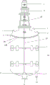
Fig. 1 is a schematic view of the overall structure of the present invention.
Detailed Description
The present invention will be further described with reference to the following examples.
The following examples are intended to illustrate the invention, but are not intended to limit the scope of the invention. The condition in the embodiment can be further adjusted according to concrete condition the utility model discloses a it is right under the design prerequisite the utility model discloses a simple improvement of method all belongs to the utility model discloses the scope of claiming.
As shown in fig. 1, a hydrolysis medicament mixing device comprises a tank 12, wherein a feed inlet 3 is arranged at the upper part of the tank 12, and a discharge outlet 9 is arranged at the lower part of the tank 12; a stirring motor 1 is further fixed above the top of the tank body 12, the stirring motor 1 is connected with a stirring shaft 13 through a speed reducer 2, the stirring shaft 13 extends downwards to the inside of the tank body 12, a first blade 8 is mounted at the bottom of the stirring shaft 13, the first blade 8 is close to the bottom of the inner wall of the tank body 12, and the shape of the first blade 8 is matched with the shape of the bottom of the inner wall of the tank body 12; the stirring shaft 13 is also provided with a plurality of second blades 7, and the top end of each second blade 7 is close to the inner side wall of the tank body 12; the upper part of the tank body 12 is also provided with a water inlet 4, the water inlet 4 is connected with a perforated pipe 14, the perforated pipe 14 is fixed on the upper part of the inner wall of the tank body 12 in a surrounding manner, and the perforated pipe 14 is uniformly provided with water outlet holes 141; and a right-angle elbow discharging pipe 10 is arranged on the discharging port 9.
The upper part of the tank body 12 is also provided with an exhaust hole 5 and a manhole 6, and the bottom is also provided with a sewage draining outlet 11. The top of the tank body 12 is provided with a support 15, and the stirring motor 1 and the speed reducer 2 are fixed on the support 15.
The working principle of the device is as follows: sequentially enters the tank according to the sequence of water, medicament and water. Water enters from the water inlet and flows into the tank through the perforated pipe. In the medicament powder got into jar from the feed inlet, start agitator motor in the medicament gets into jar, first paddle can stir the medicament of jar bottom in, avoids the medicament to precipitate, still has the function that promotes the ejection of compact simultaneously, and the second paddle is close to the jar wall, is favorable to medicament and the abundant mixing of water and alleviates jar wall scale deposit. The discharging pipe is arranged in a right-angle elbow form, so that smooth discharging is facilitated, and the discharging pipe is effectively prevented from being blocked. The ejection of compact is ended, and it is intake from the water inlet once more, flows into in the jar through the perforated pipe, erodees, avoids the jar wall to remain medicament solution extension jar wall scale deposit cycle, and can carry out the secondary to the discharging pipe and erode, avoids the discharging pipe scale deposit.
Although embodiments of the present invention have been shown and described, it will be appreciated by those skilled in the art that changes, modifications, substitutions and alterations can be made in these embodiments without departing from the principles and spirit of the invention, the scope of which is defined in the appended claims and their equivalents.
Claims (5)
1. The utility model provides a medicament mixing arrangement hydrolysises, its includes a jar body, the upper portion of jar body is provided with the feed inlet, the lower part is provided with discharge gate, its characterized in that: a stirring motor is further fixed above the top of the tank body and is connected with a stirring shaft through a speed reducer, the stirring shaft extends downwards to the inside of the tank body, a first paddle is mounted at the bottom of the stirring shaft and is close to the bottom of the inner wall of the tank body, a plurality of second paddles are further mounted on the stirring shaft, and the top end of each second paddle is close to the inner side wall of the tank body; the upper part of the tank body is also provided with a water inlet which is connected with a perforated pipe, and the perforated pipe is fixed on the upper part of the inner wall of the tank body in a surrounding manner; and a right-angle elbow discharging pipe is arranged on the discharging port.
2. The hydrolytic agent mixing device of claim 1, wherein: the shape of the first paddle is matched with the shape of the bottom of the inner wall of the tank body.
3. The hydrolytic agent mixing device of claim 1, wherein: the upper portion of the tank body is also provided with an exhaust hole and a manhole, and the bottom of the tank body is also provided with a sewage draining outlet.
4. The hydrolytic agent mixing device of claim 1, wherein: the top of the tank body is provided with a support, and the stirring motor and the speed reducer are fixed on the support.
5. The hydrolytic agent mixing device of claim 1, wherein: the perforated pipe is evenly provided with water outlet holes.
Priority Applications (1)
| Application Number | Priority Date | Filing Date | Title |
|---|---|---|---|
| CN202222242970.5U CN218741421U (en) | 2022-08-25 | 2022-08-25 | Hydrolysis medicament mixing arrangement |
Applications Claiming Priority (1)
| Application Number | Priority Date | Filing Date | Title |
|---|---|---|---|
| CN202222242970.5U CN218741421U (en) | 2022-08-25 | 2022-08-25 | Hydrolysis medicament mixing arrangement |
Publications (1)
| Publication Number | Publication Date |
|---|---|
| CN218741421U true CN218741421U (en) | 2023-03-28 |
Family
ID=85692348
Family Applications (1)
| Application Number | Title | Priority Date | Filing Date |
|---|---|---|---|
| CN202222242970.5U Active CN218741421U (en) | 2022-08-25 | 2022-08-25 | Hydrolysis medicament mixing arrangement |
Country Status (1)
| Country | Link |
|---|---|
| CN (1) | CN218741421U (en) |
-
2022
- 2022-08-25 CN CN202222242970.5U patent/CN218741421U/en active Active
Similar Documents
| Publication | Publication Date | Title |
|---|---|---|
| CN214346441U (en) | A reation kettle for water-reducing agent production | |
| CN218741421U (en) | Hydrolysis medicament mixing arrangement | |
| CN213859977U (en) | Be applied to concrete mixing ware of concrete production line | |
| CN211026125U (en) | Sewage treatment is with dissolving medicine agitating unit | |
| CN107584668A (en) | A kind of cement stirring device for saving automatic cyclic cleaning | |
| CN208603894U (en) | A kind of infant industry sewage treatment chemicals dosing plant | |
| CN208392325U (en) | A kind of concrete mixer stirred evenly | |
| CN216737705U (en) | Flocculation stirring integration medicine system | |
| CN213617525U (en) | Self-cleaning cement mixer | |
| CN212770036U (en) | Chrome tanning wastewater sedimentation device | |
| CN205095708U (en) | Dedicated automatic mixer of sewage treatment | |
| CN208213052U (en) | A kind of architectural engineering Efficient Agitator | |
| CN207056477U (en) | A kind of industrial chemicals agitating device | |
| CN209665845U (en) | Ready-mixed concrete stock stirring device | |
| CN208372920U (en) | A kind of agitating device of food inspection | |
| CN211514264U (en) | Concrete additive proportioning device | |
| CN215161666U (en) | High-efficient sewage treatment device | |
| CN215799488U (en) | Vertical high-concentration anaerobic fermentation tank | |
| CN213376200U (en) | High-efficient agitating unit | |
| CN220159982U (en) | Reaction kettle for veratrole | |
| CN204625222U (en) | Telescopic mixing reactor | |
| CN211246278U (en) | High-efficiency stirrer | |
| CN218255903U (en) | Special mixing arrangement of ready-mixed mortar | |
| CN219744572U (en) | Planetary mixer capable of effectively preventing materials from adhering | |
| CN218590233U (en) | Plant raw material mixing device convenient to ration is diluted |
Legal Events
| Date | Code | Title | Description |
|---|---|---|---|
| GR01 | Patent grant | ||
| GR01 | Patent grant |