CN218715398U - Vertical bar planting tool - Google Patents
Vertical bar planting tool Download PDFInfo
- Publication number
- CN218715398U CN218715398U CN202222930792.5U CN202222930792U CN218715398U CN 218715398 U CN218715398 U CN 218715398U CN 202222930792 U CN202222930792 U CN 202222930792U CN 218715398 U CN218715398 U CN 218715398U
- Authority
- CN
- China
- Prior art keywords
- square steel
- groove
- base
- activity
- bar planting
- Prior art date
- Legal status (The legal status is an assumption and is not a legal conclusion. Google has not performed a legal analysis and makes no representation as to the accuracy of the status listed.)
- Active
Links
Images


Landscapes
- Soil Working Implements (AREA)
Abstract
The utility model relates to a construction tool technical field specifically is a vertical bar planting instrument, the on-line screen storage device comprises a base, support the square steel, activity square steel and electric hammer, the base is the cross structure setting, and the base lower extreme is equipped with the removal subassembly, support the vertical base center upper end of locating of square steel, the square steel upper end setting of support is pegged graft through promotion subassembly activity to the activity square steel, and the promotion subassembly includes control gear, handrail and two welded plates, install the electric hammer in activity square steel upper end through the installation component, then carry out the active control through promoting the subassembly with the square steel of support and be connected, when needing to carry out bar planting punching operation to the beam slab lower extreme, need not to go on the operation of ascending a height, and can not take place the direct people's constructor contact of dust, influence the efficiency and the effect of construction, in addition under the regulating action of removal subassembly, carry out fast switch over with stable state of placing, it is that the construction is stable, easy operation convenient to use.
Description
Technical Field
The utility model relates to a construction tool technical field specifically is a vertical bar planting instrument.
Background
The steel bar planting is commonly used in the punching construction process of the building beam slab, at present, the bottom of the traditional beam slab needs to be punched manually and then the steel bar planting operation is carried out manually;
in the prior art, the operation needs workers to use a herringbone ladder, and after ascending, an electric hammer is adopted to vertically plant ribs at the bottom of a beam slab for punching;
but the in-process of punching produces a large amount of dust, often appears because of the dust leads to the unclear circumstances such as pore-forming off normal, bar planting pore-forming quality is unqualified that cause of sight, has the potential safety hazards such as serious high altitude falls when ascending a height the operation simultaneously.
SUMMERY OF THE UTILITY MODEL
An object of the utility model is to provide a vertical bar planting instrument to solve the problem that proposes in the above-mentioned background art.
In order to achieve the above object, the utility model provides a following technical scheme: the utility model provides a vertical bar planting instrument, vertical bar planting instrument includes:
the base is arranged in a cross structure, and a moving assembly is arranged at the lower end of the base;
the supporting square steel is vertically arranged at the upper end of the center of the base;
the movable square steel is movably inserted into the upper end of the supporting square steel through a lifting assembly, and the lifting assembly comprises a control gear, a handrail and two welding plates;
the electric hammer is arranged at the upper end of one side of the movable square steel through the mounting assembly.
Preferably, support the square steel upper end and seted up and accomodate the groove, accomodate that one side runs through and seted up the bar groove in the groove, the integrative vertical grafting post that is equipped with of activity square steel lower extreme, the groove setting is accomodate in grafting post lower extreme activity grafting, and the vertical welding in grafting post one side is equipped with the pinion rack, and the pinion rack runs through the setting of grafting bar groove.
Preferably, two the welding board is vertical welding respectively and is located and supports square steel upper end both sides, runs through the grafting through the bearing level between two welding boards and is equipped with the control shaft, and control gear is integrative to be cup jointed and locates on the control shaft, and pinion rack one side symmetry is equipped with a plurality of teeth, and control gear one side tooth links to each other with pinion rack one side tooth meshing, and handrail one side welding is equipped with the positioning disk, and the positioning disk center links to each other with control shaft through welding board one side welding.
Preferably, one side the horizontal flat-open of welding plate internal level is equipped with the spring groove, and the level runs through welding plate both sides grafting and is equipped with the gag lever post in the spring inslot, and the integrative push jack that is equipped with in spring inslot one side is arranged in to the gag lever post, and the gag lever post is close to push jack one side and cup joints and be equipped with the extrusion spring, and the positioning disk is close to welding plate one side symmetric ring and is equipped with a plurality of spacing grooves, and the gag lever post runs through welding plate one side and pegs graft and arrange the spacing inslot in.
Preferably, the installation component is including placing the support, places support level welding and locates activity square steel one side upper end, and the electric hammer is vertical to be placed and to be located on placing the support, and the electric hammer cup joints with activity square steel upper end and is equipped with a plurality of binding hoops that excel in.
Preferably, the lower end of the base is horizontally provided with a configuration disc, four movable grooves are symmetrically formed in four sides of the base, a sleeving shaft is horizontally arranged in each movable groove, the moving assembly comprises four universal wheels, and the upper ends of the four universal wheels are respectively inserted into the movable grooves and movably sleeved on the sleeving shaft.
Preferably, the base is located the activity groove and is all leveled and be equipped with the diaphragm, and diaphragm one side all runs through and has seted up the arc wall, and universal wheel one side all is equipped with the arc pole, and arc pole one side grafting arc wall sets up, all cup joints on the arc pole and is equipped with reset spring, and the base is located activity groove one side and all is equipped with the accessory plate, and the accessory plate has all seted up the opening groove with diaphragm one side, and the universal wheel upper end is equal vertical to be equipped with locking screw, and locking screw runs through one side opening groove setting, and locking screw runs through opening groove one side and cup joints through the screw thread and is equipped with butterfly nut.
Preferably, the vertical guide post that is equipped with in base one side upper end, activity square steel one side lower extreme horizontal symmetry is equipped with a plurality of pieces that cup joint, and a plurality of pieces that cup joint are the activity respectively and cup joint the guide post upper end setting, and one side level of a side welded plate is equipped with the mounting panel, and the mounting panel upper end is equipped with the pilot lamp.
Compared with the prior art, the beneficial effects of the utility model are that:
install the electric hammer in activity square steel upper end through the installation component, then will move about square steel and support square steel through the hoisting component and carry out the active control and be connected, carry out the bar planting to the beam slab lower extreme when punching the operation, need not to ascend a height the operation, and can not take place the direct people constructor contact of dust, influence the efficiency and the effect of construction, under the regulating action of removal subassembly, remove and stably place the state and carry out the fast switch-over in addition, it is construction stability, easy operation convenient to use.
Drawings
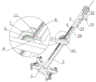
FIG. 1 is a schematic structural view of the present invention;
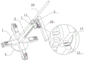
FIG. 2 is a schematic view of the lifting assembly of the present invention;
FIG. 3 is a schematic view of the connection structure of the control gear of the present invention;
FIG. 4 is a schematic view of the movable square steel structure of the present invention;
fig. 5 is a schematic view of the base structure of the present invention.
In the figure: base 1, support square steel 2, activity square steel 3, spliced pole 4, accomodate groove 5, pinion rack 6, welded plate 7, control gear 8, positioning disk 9, handrail 10, pilot lamp 11, gag lever post 12, spacing groove 13, configuration dish 14, universal wheel 15, diaphragm 16, arc pole 17, locking screw 18, butterfly nut 19, guide post 20, cover joint piece 21, place support 22, electric hammer 23.
Detailed Description
The technical solutions in the embodiments of the present invention will be described clearly and completely with reference to the accompanying drawings in the embodiments of the present invention, and it is obvious that the described embodiments are only some embodiments of the present invention, not all embodiments. Based on the embodiments in the present invention, all other embodiments obtained by a person skilled in the art without creative work belong to the protection scope of the present invention.
Referring to fig. 1-5, the present application provides the following three preferred embodiments.
Example one
The utility model provides a vertical bar planting instrument, vertical bar planting instrument includes:
the base 1, the base 1 is arranged in a cross structure, a moving assembly is arranged at the lower end of the base 1, a configuration disc 14 is horizontally arranged at the lower end of the base 1, four movable grooves are symmetrically formed in four sides of the base 1, a sleeve shaft is horizontally arranged in each movable groove, each moving assembly comprises four universal wheels 15, the upper ends of the four universal wheels 15 are respectively inserted into the movable grooves and movably sleeved on the sleeve shaft, a transverse plate 16 is horizontally arranged on each movable groove of the base 1, an arc-shaped groove is formed in each transverse plate 16 in a penetrating mode, an arc-shaped rod 17 is arranged on each universal wheel 15 in a penetrating mode, an arc-shaped groove is arranged in each arc-shaped rod 17 in a penetrating mode, a reset spring is sleeved on each arc-shaped rod 17, an auxiliary plate is arranged on each movable groove of the base 1, grooves are formed in each auxiliary plate and one side of the transverse plate 16, locking screws 18 are vertically arranged at the upper ends of the universal wheels 15, each locking screw 18 penetrates through one side of the groove, and each locking screw 18 penetrates through one side of the groove and is sleeved with a butterfly nut 19 through threads;
the supporting square steel 2 is vertically arranged at the upper end of the center of the base 1, the upper end of the supporting square steel 2 is provided with a containing groove 5, one side in the containing groove 5 is provided with a strip-shaped groove in a penetrating manner, the lower end of the movable square steel 3 is integrally and vertically provided with an inserting column 4, the lower end of the inserting column 4 is movably inserted into the containing groove 5, one side of the inserting column 4 is vertically welded with a toothed plate 6, and the toothed plate 6 penetrates through the inserting strip-shaped groove;
the movable square steel 3 is movably inserted and supported at the upper end of the square steel 2 through a lifting assembly, the lifting assembly comprises a control gear 8, a handrail 10 and two welding plates 7, the two welding plates 7 are respectively vertically welded and arranged on two sides of the upper end of the square steel 2, a control shaft is horizontally inserted and connected between the two welding plates 7 through a bearing, the control gear 8 is integrally sleeved on the control shaft, a plurality of teeth are symmetrically arranged on one side of the toothed plate 6, one side of the control gear 8 is meshed and connected with one side of the toothed plate 6, a positioning disc 9 is welded on one side of the handrail 10, the center of the positioning disc 9 is welded and connected with one side of the control shaft penetrating and welding plate 7, a spring groove is horizontally formed in one side of the welding plate 7, limiting rods 12 are inserted and connected on two sides of the horizontal penetrating and welding plate 7 in the spring groove, a push sheet is integrally arranged on one side of the limiting rods 12 in the spring groove, an extrusion spring is sleeved and arranged on one side of the limiting rods 12 close to the push sheet, a plurality of limiting grooves 13 are symmetrically arranged on one side of the positioning disc 9 close to the welding plate 7, and one side of the limiting rods 12 is inserted and connected in the limiting groove 13;
Example two
On the basis of embodiment one, the vertical guide post 20 that is equipped with in base 1 one side upper end, 3 one side lower extreme horizontal symmetry of activity square steel are equipped with a plurality of splicing blocks 21, and a plurality of splicing blocks 21 are the activity respectively and are cup jointed the setting of guide post 20 upper end, strengthen the upper and lower activity direction and the support stability of activity square steel 3.
EXAMPLE III
On the basis of embodiment two, one side level of one side welded plate 7 is equipped with the mounting panel, and the mounting panel upper end is equipped with pilot lamp 11, indicates electric hammer 23 position of punching, facilitates the use, raises the efficiency.
When the device is used, the butterfly nuts 19 are loosened, the universal wheels 15 are rotated into the movable grooves, the butterfly nuts 19 are screwed at the upper ends of the auxiliary plates to be positioned, the configuration disc 14 is contacted with the ground, the stability of integral erection during subsequent operation is kept, then the limiting rod 12 is pulled out by using a common wood or plastic product clamping pin in the prior art, one side of the limiting rod 12 is separated from the limiting groove 13, the handrail 10 is held to rotate continuously, the control gear 8 is driven to lift the toothed plate 6 and the inserting column 4, so that the movable square steel 3 and the electric hammer 23 are used for punching the bottom of the beam plate, the indicating lamp 11 is matched to perform pointing operation in the process, the operation is simple and convenient to use, the limiting rod 12 is inserted into the limiting groove 13 to limit the movement of the butterfly nuts 10 when the position of the electric hammer 23 is static or the butterfly nuts are reset after use are finished, then the four universal wheels 15 are loosened, the four universal wheels 15 are automatically ejected under the action of the reset spring, and the butterfly nuts 19 are held to perform the movement of the integral device after the butterfly nuts 19 are tightened, thereby saving worry and saving labor.
Although embodiments of the present invention have been shown and described, it will be appreciated by those skilled in the art that changes, modifications, substitutions and alterations can be made in these embodiments without departing from the principles and spirit of the invention, the scope of which is defined in the appended claims and their equivalents.
Claims (8)
1. The utility model provides a vertical bar planting instrument which characterized in that: vertical bar planting instrument includes:
the base (1), the base (1) is arranged in a cross structure, and the lower end of the base (1) is provided with a moving assembly;
the supporting square steel (2), the supporting square steel (2) is vertically arranged at the upper end of the center of the base (1);
the movable square steel (3) is movably inserted into the upper end of the supporting square steel (2) through a lifting assembly, and the lifting assembly comprises a control gear (8), a handrail (10) and two welding plates (7);
electric hammer (23), electric hammer (23) are located activity square steel (3) one side upper end through the installation component.
2. The vertical bar planting tool of claim 1, wherein: support square steel (2) upper end and seted up and accomodate groove (5), accomodate one side and run through and seted up the bar groove in groove (5), the integrative vertical grafting post (4) that are equipped with of activity square steel (3) lower extreme, grafting post (4) lower extreme activity is pegged graft and is accomodate groove (5) setting, and the vertical welding in grafting post (4) one side is equipped with pinion rack (6), and pinion rack (6) run through the setting of grafting bar groove.
3. The vertical bar planting tool of claim 2, wherein: two vertical welding is located respectively in welded plate (7) and is supported square steel (2) upper end both sides, runs through the grafting through the bearing level between two welded plates (7) and is equipped with the control shaft, control gear (8) an organic whole cup joints and locates on the control shaft, pinion rack (6) one side symmetry is equipped with a plurality of teeth, control gear (8) one side tooth links to each other with pinion rack (6) one side tooth meshing, handrail (10) one side welding is equipped with positioning disk (9), positioning disk (9) center and control shaft run through welded plate (7) one side welding and link to each other.
4. The vertical bar planting tool of claim 3, wherein: one side the horizontal flat of welding plate (7) water-logging is equipped with the spring groove, and the level of spring inslot runs through welding plate (7) both sides and pegs graft and is equipped with gag lever post (12), and integrative being equipped with the push jack in spring inslot one side is arranged in gag lever post (12), and gag lever post (12) are close to push jack one side and cup joint and are equipped with the extrusion spring, and positioning disk (9) are close to welding plate (7) one side symmetric ring and are equipped with a plurality of spacing grooves (13), and gag lever post (12) run through welding plate (7) one side and peg graft and arrange in spacing groove (13).
5. The vertical bar planting tool of claim 4, wherein: the mounting assembly comprises a placing support (22), the placing support (22) is horizontally welded to the upper end of one side of the movable square steel (3), the electric hammer (23) is vertically placed on the placing support (22), and a plurality of high-strength binding hoops are sleeved on the upper ends of the electric hammer (23) and the movable square steel (3).
6. The vertical bar planting tool of claim 5, wherein: the movable assembly is characterized in that a configuration disc (14) is horizontally arranged at the lower end of the base (1), four movable grooves are symmetrically formed in four sides of the base (1), a sleeve connecting shaft is horizontally arranged in each movable groove, the movable assembly comprises four universal wheels (15), and the upper ends of the four universal wheels (15) are respectively inserted into the movable grooves and movably sleeved on the sleeve connecting shaft.
7. The vertical bar planting tool of claim 6, wherein: base (1) is located the activity groove and is equallyd divide the level and be equipped with diaphragm (16), diaphragm (16) one side all runs through and has seted up the arc wall, universal wheel (15) one side all is equipped with arc pole (17), arc pole (17) one side grafting arc wall setting, all cup joint on arc pole (17) and be equipped with reset spring, base (1) is located activity groove one side and all is equipped with the accessory plate, the opening groove has all been seted up with diaphragm (16) one side to the accessory plate, universal wheel (15) upper end is equal vertical to be equipped with locking screw (18), locking screw (18) run through one side opening groove setting, and locking screw (18) run through opening groove one side and cup joint through the screw and be equipped with butterfly nut (19).
8. The vertical bar planting tool of claim 7, wherein: the vertical guide post (20) that is equipped with in base (1) one side upper end, activity square steel (3) one side lower extreme horizontal symmetry is equipped with a plurality of cover and connects piece (21), and a plurality of cover connect piece (21) respectively the activity cup joint guide post (20) upper end setting, and one side level of one side welded plate (7) is equipped with the mounting panel, and the mounting panel upper end is equipped with pilot lamp (11).
Priority Applications (1)
| Application Number | Priority Date | Filing Date | Title |
|---|---|---|---|
| CN202222930792.5U CN218715398U (en) | 2022-11-04 | 2022-11-04 | Vertical bar planting tool |
Applications Claiming Priority (1)
| Application Number | Priority Date | Filing Date | Title |
|---|---|---|---|
| CN202222930792.5U CN218715398U (en) | 2022-11-04 | 2022-11-04 | Vertical bar planting tool |
Publications (1)
| Publication Number | Publication Date |
|---|---|
| CN218715398U true CN218715398U (en) | 2023-03-24 |
Family
ID=85605571
Family Applications (1)
| Application Number | Title | Priority Date | Filing Date |
|---|---|---|---|
| CN202222930792.5U Active CN218715398U (en) | 2022-11-04 | 2022-11-04 | Vertical bar planting tool |
Country Status (1)
| Country | Link |
|---|---|
| CN (1) | CN218715398U (en) |
-
2022
- 2022-11-04 CN CN202222930792.5U patent/CN218715398U/en active Active
Similar Documents
| Publication | Publication Date | Title |
|---|---|---|
| CN111536396A (en) | Measuring device for municipal works | |
| CN218715398U (en) | Vertical bar planting tool | |
| CN109339425B (en) | Supporting platform for building construction and installation method thereof | |
| CN202009181U (en) | Mounting device for isolating switch mechanism case | |
| CN203097332U (en) | Wood-plastic quadrangular pavilion | |
| CN209976063U (en) | Device for repairing historic building wooden column | |
| CN214834533U (en) | Scaffold frame for municipal works | |
| CN214834659U (en) | Attached supporting steel frame | |
| CN210976074U (en) | Steel structure building component | |
| CN112096037B (en) | Scaffold frame that can safe location construction | |
| CN211850282U (en) | Roof structure of steel structure factory building | |
| CN212743499U (en) | Adjustable stable supporting structure for historic building restoration | |
| CN210316658U (en) | Supporting device for repairing ancient buildings | |
| CN211151173U (en) | High-voltage fireproof power distribution cabinet for tower crane | |
| CN210460064U (en) | Novel building structure supports device | |
| CN211597849U (en) | Building templates for building engineering | |
| CN205476818U (en) | Covering or awning on a car, boat, etc. room structure | |
| CN111502218A (en) | Construction frame | |
| CN217232892U (en) | High stability strutting arrangement for civil engineering | |
| CN213909066U (en) | Drawing equipment for height-adjustable's architectural design | |
| CN212802422U (en) | Scaffold | |
| CN214384040U (en) | Liftable scaffold for building engineering | |
| CN215671184U (en) | Adjustable movable splicing platform for trapezoidal steel roof truss | |
| CN218757911U (en) | Steel construction factory building package assembly | |
| CN217451590U (en) | Straightening machine for steel structure machining |
Legal Events
| Date | Code | Title | Description |
|---|---|---|---|
| GR01 | Patent grant | ||
| GR01 | Patent grant |