CN218700252U - Stone cutting device - Google Patents
Stone cutting device Download PDFInfo
- Publication number
- CN218700252U CN218700252U CN202222511141.2U CN202222511141U CN218700252U CN 218700252 U CN218700252 U CN 218700252U CN 202222511141 U CN202222511141 U CN 202222511141U CN 218700252 U CN218700252 U CN 218700252U
- Authority
- CN
- China
- Prior art keywords
- moving mechanism
- cutting device
- guide rail
- stone
- driver
- Prior art date
- Legal status (The legal status is an assumption and is not a legal conclusion. Google has not performed a legal analysis and makes no representation as to the accuracy of the status listed.)
- Active
Links
Images


Classifications
-
- Y—GENERAL TAGGING OF NEW TECHNOLOGICAL DEVELOPMENTS; GENERAL TAGGING OF CROSS-SECTIONAL TECHNOLOGIES SPANNING OVER SEVERAL SECTIONS OF THE IPC; TECHNICAL SUBJECTS COVERED BY FORMER USPC CROSS-REFERENCE ART COLLECTIONS [XRACs] AND DIGESTS
- Y02—TECHNOLOGIES OR APPLICATIONS FOR MITIGATION OR ADAPTATION AGAINST CLIMATE CHANGE
- Y02P—CLIMATE CHANGE MITIGATION TECHNOLOGIES IN THE PRODUCTION OR PROCESSING OF GOODS
- Y02P40/00—Technologies relating to the processing of minerals
- Y02P40/50—Glass production, e.g. reusing waste heat during processing or shaping
- Y02P40/57—Improving the yield, e-g- reduction of reject rates
Landscapes
- Processing Of Stones Or Stones Resemblance Materials (AREA)
Abstract
The utility model belongs to the technical field of stone material processing equipment technique and specifically relates to a stone material cutting device. It includes cutting mechanism, moving mechanism and actuating mechanism, actuating mechanism includes electric actuator and manual drive ware, electric actuator control cutting mechanism operates and moving mechanism carries out left and right sides adjustment and seesaw, the last fixture that still is provided with of moving mechanism, fixture has the elasticity holder, manual drive ware control fixture presss from both sides tightly or unclamps. It has the advantages that: the moving mechanism is controlled to perform left-right adjustment and front-back movement in an electric driving mode, on one hand, labor is saved, operation is not required all the time, and the machine can start to work only by setting parameters, so that convenience and trouble are saved, on the other hand, the running speed is uniform and controllable, so that the cutting quality is higher, and the cutting surface is more uniform; the stone setting machine is provided with an operation screen and a controller, and can set different parameters for different stones. The best cutting effect is achieved.
Description
Technical Field
The utility model belongs to the technical field of stone material processing equipment technique and specifically relates to a stone material cutting device.
Background
The stone cutting device can cut various types of stones, has high processing efficiency, can process small stones again, saves stone resources, is favorable for environmental protection and resource recycling, and reduces the production cost.
The existing stone cutting device, particularly an agate raw stone cutting device, needs an operator to operate in the whole process, manually feed and manually adjust the cutting position in the use process, so that the problems that firstly, the labor cost is high, time and labor are wasted, secondly, the operation process cannot achieve uniform cutting, the cutting quality is reduced to a certain extent, and uneven cutting marks may exist on a cut surface are caused; in addition, different methods and cutting specifications are provided for cutting different stone materials, operators need to be trained, the problems that the required cutting speed cannot be quickly changed due to different stone material textures and the like in manual operation still exist, the production cost is high, and the cutting effect and the cutting quality have certain defects.
Based on this, the applicant has proposed a stone cutting device to solve the above technical problems.
SUMMERY OF THE UTILITY MODEL
The utility model provides a stone material cutting device to not enough among the prior art, it has overcome foretell drawback, and the technical scheme of its adoption is as follows:
the utility model provides a stone material cutting device, includes cutting mechanism, moving mechanism and actuating mechanism, actuating mechanism includes electric actuator and manual drive ware, electric actuator controls cutting mechanism operates and moving mechanism carries out left and right sides adjustment and seesaw, the last fixture that still is provided with of moving mechanism, fixture has the elasticity holder, manual drive ware control fixture presss from both sides tightly or unclamps.
Preferably, the moving mechanism comprises a longitudinal moving mechanism and a transverse moving mechanism, and the electric driver comprises a driver A for controlling the longitudinal moving mechanism to move back and forth, an electronic push rod for controlling the transverse moving mechanism to move left and right, and a driver B for controlling the cutting mechanism to operate.
Preferably, the driver A comprises a motor A, the motor A is connected with a screw rod A, the screw rod A is sleeved on a feeding nut, and the feeding nut is connected with the longitudinal moving mechanism.
Preferably, the longitudinal movement mechanism comprises a guide rail A, a slider A and a bottom dragging plate, the guide rail A is fixedly connected to the upper side of the fixing mechanism, the lower side of the slider A is in sliding connection with the guide rail A, the upper side of the slider A is fixedly connected to the lower side of the bottom dragging plate, and the transverse movement mechanism is in sliding connection with the upper side of the bottom dragging plate.
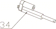
Preferably, the electronic push rod is a telescopic rod, one end of the electronic push rod is connected to the transverse moving mechanism, and the other end of the electronic push rod is connected to the longitudinal moving mechanism.
Preferably, the transverse moving mechanism comprises a sliding block B, a guide rail B and a middle carriage, the sliding block B is fixedly connected to the upper side of the bottom carriage, the lower side of the guide rail B is in sliding connection with the sliding block B, the upper side of the guide rail B is fixedly connected to the lower side of the middle carriage, and the clamping mechanism is arranged on the upper side of the middle carriage.
Preferably, driver B includes motor B, motor B is connected with the belt pulley through driving belt, the belt pulley with cutting mechanism's main shaft is connected, cutting mechanism is still including installing main epaxial saw bit, the main shaft passes through bushing connection on stand A, still be provided with the oil-proof lid on the main shaft, stand A connects on the bottom plate, the bottom plate with fixed establishment connects.
Preferably, the manual driver comprises a fixing nut arranged on the upper side of the middle carriage, the fixing nut is connected with a lead screw B in a matching mode, one end, far away from the fixing nut, of the lead screw B is fixedly connected with a hand wheel, the hand wheel is connected with the upper carriage through a connecting plate and controls a clamping mechanism on the upper carriage to clamp or loosen, a guide rail C is installed on the lower side of the upper carriage, and a flange sliding block corresponding to the guide rail C is installed on the upper side of the middle carriage.
Preferably, fixture includes the rigid coupling and is in go up the stand B and the sliding connection of planker upside go up the stand C of planker upside, motor C is installed to stand B one side, and the opposite side is installed the elasticity holder, the elasticity holder is the PU cover, motor C control the PU cover is rotatory, also install the PU cover through pressing from both sides the stone axle sleeve on the stand C.
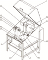
Preferably, the fixing mechanism comprises a mounting plate, the lower side of the mounting plate is connected with the shell, the upper side of the mounting plate is connected with a front beam, the two ends of the front beam are connected with longitudinal beams, the longitudinal beams are connected with a rear beam, the rear beam is connected with the bottom plate, the longitudinal beams are connected with the guide rail A, an operation screen and a controller are arranged on the outer side of the shell and used for controlling the driving mechanism, and the collecting box is placed on the lower side of the shell.
Compared with the prior art, the beneficial effects of the utility model reside in that: the moving mechanism is controlled to perform left-right adjustment and front-back movement in an electric driving mode, on one hand, labor is saved, operation is not required all the time, and the machine can start to work only by setting parameters, so that convenience and trouble are saved, on the other hand, the running speed is uniform and controllable, so that the cutting quality is higher, and the cutting surface is more uniform; the stone setting machine is provided with an operation screen and a controller, and can set different parameters for different stones. The best cutting effect is achieved.
Drawings
In order to more clearly illustrate the embodiments of the present invention or the technical solutions in the prior art, the following will discuss the drawings required to be used in the description of the embodiments or the prior art, it is obvious that the technical solutions described in conjunction with the drawings are only some embodiments of the present invention, and for those skilled in the art, other embodiments and drawings thereof can be obtained according to the embodiments shown in the drawings without creative efforts.
Fig. 1 is a schematic perspective view of the present invention.
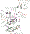
Fig. 2 is an exploded view of the internal structure of the present invention.
Fig. 3 is a schematic view of the internal three-dimensional structure of the present invention.
Fig. 4 is a schematic view of the internal three-dimensional structure of the present invention.
Fig. 5 is a schematic view of the internal three-dimensional structure of the present invention.
Fig. 6 is a schematic view of a partial internal three-dimensional structure of the present invention.
Fig. 7 is a schematic perspective view of the moving mechanism of the present invention.
Fig. 8 is a schematic perspective view of the cutting mechanism of the present invention.
Fig. 9 is a schematic view of a three-dimensional structure of the electronic push rod of the present invention.
In the figure: 1. the device comprises a shell, 2, a collecting box, 301, a feeding nut, 302, a fixing nut, 31, motors A,32, motors B,33, motors C,34, an electronic push rod, 35, a hand wheel, 36, a screw rod A,37, a belt pulley, 38, a transmission belt, 39, a screw rod B,41, a guide rail A,42, a slide block A,43, a bottom dragging plate, 44, a slide block B,45, a guide rail B,46, a middle dragging plate, 47, a flange slide block, 48, a guide rail C,49, an upper dragging plate, 51, a main shaft, 52, a saw blade, 53, an oil-proof cover, 54, a sleeve, 55, a stand column A,56, a bottom plate, 61, a stand column B,62, a PU sleeve, 63, a stone clamping sleeve, 64, a stand column C,65, a connecting plate, 7, a rear beam, 8, a front beam, 9, a longitudinal beam, 10, a mounting plate, 11, an operation screen, 12 and a controller.
Detailed Description
The technical solutions of the embodiments of the present invention will be described clearly and completely with reference to the accompanying drawings, and it is to be understood that the described embodiments are only some embodiments of the present invention, and not all embodiments. Based on the embodiments described in the present disclosure, all other embodiments obtained by a person skilled in the art without creative efforts are within the scope of the present disclosure.
Example 1:
as shown in fig. 1 to 9, an embodiment of the present invention provides a stone cutting device, which includes a cutting mechanism, a moving mechanism and a driving mechanism, wherein the driving mechanism includes an electric driver and a manual driver, the moving mechanism includes a longitudinal moving mechanism and a transverse moving mechanism, the electric driver includes a driver a for controlling the longitudinal moving mechanism to move back and forth, an electronic push rod 34 for controlling the transverse moving mechanism to move left and right, and a driver B for controlling the cutting mechanism to operate, the driver a includes a motor a31, the motor a31 is connected with a lead screw a36, the lead screw a36 is sleeved on a feed nut 301, the feed nut 301 is connected with the longitudinal moving mechanism, the longitudinal moving mechanism includes a guide rail a41, a slider a42, and a bottom dragging plate 43, the guide rail a41 is fixedly connected to the upper side of the fixing mechanism, the lower side of the slider a42 is slidably connected to the guide rail a41, the upper side of the sliding block A42 is fixedly connected to the lower side of the bottom carriage 43, the transverse moving mechanism is slidably connected to the upper side of the bottom carriage 43, the electronic push rod 34 is a telescopic rod, one end of the electronic push rod 34 is connected to the transverse moving mechanism, the other end of the electronic push rod is connected to the longitudinal moving mechanism, the transverse moving mechanism comprises a sliding block B44, a guide rail B45 and a middle carriage 46, the sliding block B44 is fixedly connected to the upper side of the bottom carriage 43, the lower side of the guide rail B45 is slidably connected to the sliding block B44, the upper side of the guide rail B45 is fixedly connected to the lower side of the middle carriage 46, the clamping mechanism is arranged on the upper side of the middle carriage 46, the driver B comprises a motor B32, the motor B32 is connected with a belt pulley 37 through a transmission belt 38, the belt pulley 37 is connected with a main shaft 51 of the cutting mechanism, and the cutting mechanism further comprises a saw blade 52 installed on the main shaft 51, spindle 51 passes through the sleeve pipe 54 and connects on stand A55, still be provided with oil-proof cover 53 on spindle 51, stand A55 connects on bottom plate 56, bottom plate 56 with fixed establishment connects, fixed establishment includes mounting panel 10, mounting panel 10 downside is connected with casing 1, mounting panel 10 upside is connected with front beam 8, front beam 8 both ends all are connected with longeron 9, be connected with back beam 7 on the longeron 9, back beam 7 with bottom plate 56 connects, longeron 9 with guide rail A41 connects, the casing 1 outside is provided with operation screen 11 and controller 12 and is used for control actuating mechanism, collecting box 2 has been placed to casing 1 downside, still be provided with fixture on the moving mechanism, fixture includes the rigid coupling and is in the stand B61 and the sliding connection of last planker 49 upside are in the stand C64 of last planker 49 upside, motor C33 is installed to stand B61 one side, the PU cover 62 is installed to the opposite side, motor C33 control PU cover 62 is rotatory, also install through stone axle sleeve 63 on stand C64 and control driver centre gripping cover 62, the fixed drive clamp is pressed from both sides and is pressed from both sides the hand wheel 48 and is connected with the hand wheel 48 the fixed mounting nut 35 and is connected with the lead screw clamp on the planker 48 the hand wheel planker 46 the fixed mounting carriage 35 the hand carriage 48 the hand wheel planker 35.
When the stone cutting machine is used, stones to be cut are placed between the PU sleeves 62 of the clamping mechanisms, the hand wheels 35 are rotated to enable the clamping mechanisms to clamp the stones, the proper saw blades 52 are selected and installed on the main shaft 51, the driving mechanisms are controlled to operate through the operation screen 11 and the controller 12, the electronic push rod 34 controls the dragging plate 46 to move left and right through stretching or contracting control to adjust the position, the motor B32 controls the belt pulley 37 to rotate through the transmission belt 38, the main shaft 51 is driven to rotate, the saw blades 52 rotate at high speed for cutting, after the position is calibrated, the motor A31 controls the screw rod A36 to rotate, so that the bottom dragging plate 43 is close to the saw blades 52, the stones are close to the saw blades 52 for cutting, scraps generated by cutting, oil stains flowing out of the machine and water used for cooling enter the collecting box 2 through the through holes in the shell 1, after cutting is completed, the movement mechanism is controlled to reset and the cutting mechanisms stop rotating through the operation screen 11 and the controller 12, the hand wheels 35 are loosened, and the cut stones are taken down.
It is obvious to a person skilled in the art that the invention is not restricted to details of the above-described exemplary embodiments, but that it can be implemented in other specific forms without departing from the spirit or essential characteristics of the invention. The present embodiments are, therefore, to be considered in all respects as illustrative and not restrictive. The scope of the invention is indicated by the appended claims, rather than the foregoing description, and all changes that come within the meaning and range of equivalency of the claims are therefore intended to be embraced therein. Any reference sign in a claim should not be construed as limiting the claim concerned.
Furthermore, it should be understood that although the present description refers to embodiments, not every embodiment may contain only a single embodiment, and such description is for clarity only, and those skilled in the art should integrate the description, and the embodiments may be combined as appropriate to form other embodiments understood by those skilled in the art.
Claims (10)
1. The utility model provides a stone material cutting device, includes cutting mechanism, moving mechanism and actuating mechanism, its characterized in that: the driving mechanism comprises an electric driver and a manual driver, the electric driver controls the cutting mechanism to operate and the moving mechanism to perform left-right adjustment and front-back movement, the moving mechanism is further provided with a clamping mechanism, the clamping mechanism is provided with an elastic clamping piece, and the manual driver controls the clamping mechanism to clamp or loosen.
2. Stone cutting device according to claim 1, characterized in that: the moving mechanism comprises a longitudinal moving mechanism and a transverse moving mechanism, and the electric driver comprises a driver A for controlling the longitudinal moving mechanism to move back and forth, an electronic push rod (34) for controlling the transverse moving mechanism to move left and right, and a driver B for controlling the cutting mechanism to operate.
3. Stone cutting device according to claim 2, characterized in that: the driver A comprises a motor A (31), the motor A (31) is connected with a screw rod A (36), the screw rod A (36) is sleeved on a feeding nut (301), and the feeding nut (301) is connected with the longitudinal moving mechanism.
4. A stone cutting device as claimed in claim 3, characterized in that: the longitudinal moving mechanism comprises a guide rail A (41), a sliding block A (42) and a bottom dragging plate (43), the guide rail A (41) is fixedly connected to the upper side of the fixing mechanism, the lower side of the sliding block A (42) is in sliding connection with the guide rail A (41), the upper side of the sliding block A (42) is fixedly connected to the lower side of the bottom dragging plate (43), and the transverse moving mechanism is in sliding connection with the upper side of the bottom dragging plate (43).
5. The stone cutting device as claimed in claim 4, wherein: the electronic push rod (34) is a telescopic rod, one end of the electronic push rod (34) is connected to the transverse moving mechanism, and the other end of the electronic push rod is connected to the longitudinal moving mechanism.
6. Stone cutting device according to claim 5, characterized in that: the transverse moving mechanism comprises a sliding block B (44), a guide rail B (45) and a middle carriage (46), the sliding block B (44) is fixedly connected to the upper side of the bottom carriage (43), the lower side of the guide rail B (45) is in sliding connection with the sliding block B (44), the upper side of the guide rail B (45) is fixedly connected to the lower side of the middle carriage (46), and the clamping mechanism is arranged on the upper side of the middle carriage (46).
7. The stone cutting device as claimed in claim 4, wherein: driver B includes motor B (32), motor B (32) are connected with belt pulley (37) through driving belt (38), belt pulley (37) with cutting mechanism's main shaft (51) are connected, cutting mechanism is still including installing saw bit (52) on main shaft (51), main shaft (51) are connected on stand A (55) through sleeve pipe (54), still be provided with on main shaft (51) and prevent oily lid (53), stand A (55) are connected on bottom plate (56), bottom plate (56) with fixed establishment connects.
8. Stone cutting device according to claim 6, characterized in that: the manual driver comprises a fixing nut (302) arranged on the upper side of the middle carriage (46), a lead screw B (39) is connected to the fixing nut (302) in a matched mode, the lead screw B (39) is far away from one end of the fixing nut (302) and is fixedly connected with a hand wheel (35), the hand wheel (35) is connected with an upper carriage (49) through a connecting plate (65), a clamping mechanism on the upper carriage (49) is controlled to clamp or loosen, a guide rail C (48) is installed on the lower side of the upper carriage (49), and a flange sliding block (47) corresponding to the guide rail C (48) is installed on the upper side of the middle carriage (46).
9. The stone cutting device as claimed in claim 8, wherein: fixture includes the rigid coupling and is in stand B (61) and the sliding connection of last planker (49) upside are in stand C (64) of last planker (49) upside, motor C (33) are installed to stand B (61) one side, and the other side is installed flexible holder, the elasticity holder is PU cover (62), motor C (33) control PU cover (62) are rotatory, also install PU cover (62) through pressing from both sides stone axle sleeve (63) on stand C (64).
10. Stone cutting device according to claim 7, characterized in that: fixing mechanism includes mounting panel (10), mounting panel (10) downside is connected with casing (1), mounting panel (10) upside is connected with front-axle beam (8), front-axle beam (8) both ends all are connected with longeron (9), be connected with back beam (7) on longeron (9), back beam (7) with bottom plate (56) are connected, longeron (9) with guide rail A (41) are connected, casing (1) outside is provided with operation screen (11) and controller (12) and is used for controlling actuating mechanism, collecting box (2) have been placed to casing (1) downside.
Priority Applications (1)
| Application Number | Priority Date | Filing Date | Title |
|---|---|---|---|
| CN202222511141.2U CN218700252U (en) | 2022-09-22 | 2022-09-22 | Stone cutting device |
Applications Claiming Priority (1)
| Application Number | Priority Date | Filing Date | Title |
|---|---|---|---|
| CN202222511141.2U CN218700252U (en) | 2022-09-22 | 2022-09-22 | Stone cutting device |
Publications (1)
| Publication Number | Publication Date |
|---|---|
| CN218700252U true CN218700252U (en) | 2023-03-24 |
Family
ID=85636056
Family Applications (1)
| Application Number | Title | Priority Date | Filing Date |
|---|---|---|---|
| CN202222511141.2U Active CN218700252U (en) | 2022-09-22 | 2022-09-22 | Stone cutting device |
Country Status (1)
| Country | Link |
|---|---|
| CN (1) | CN218700252U (en) |
-
2022
- 2022-09-22 CN CN202222511141.2U patent/CN218700252U/en active Active
Similar Documents
| Publication | Publication Date | Title |
|---|---|---|
| CN218700252U (en) | Stone cutting device | |
| CN106836803B (en) | Template repairing equipment and repairing method thereof | |
| CN115890797B (en) | Cutting device for continuously winding glass fiber reinforced plastic pipeline | |
| CN108145505A (en) | One kind is convenient for lathe handling equipment | |
| CN109732449B (en) | Automatic recycle equipment that polishes in waste paper tube surface | |
| CN213412302U (en) | Shaft sleeve plate production device | |
| CN215788739U (en) | Grinding machine is used in motor cover production | |
| CN215469971U (en) | Nonrust steel pipe burnishing and polishing device | |
| CN205538530U (en) | Diamond saw blade test bench | |
| CN112847681B (en) | Round block cutting equipment for machining round chopping board | |
| CN201320517Y (en) | Multifunctional coating machine | |
| CN217291768U (en) | Grinding device for workpiece surface treatment | |
| CN217452366U (en) | Device is tailor to various steel sheet size | |
| CN218964996U (en) | Wire drawing machine capable of feeding power to three wheels and one wheel belt | |
| CN216658210U (en) | Cutting equipment is used in processing of clear mould rubber slab | |
| CN211866742U (en) | Metal material cutting device is used in hardware and tools production | |
| CN220429461U (en) | Soft package film edge blanking device | |
| CN220560685U (en) | Panel location cutting machine | |
| CN219881784U (en) | Full-automatic micro-drilling slotting and grinding integrated machine | |
| CN211615756U (en) | Cutting equipment for processing composite plastic products | |
| CN219902764U (en) | Grooving machine for diamond thinning pad processing | |
| CN216760814U (en) | Film pasting equipment for processing surface of power line | |
| CN220881504U (en) | Reaming equipment for gear forging | |
| CN212947008U (en) | Grinding device for part machining | |
| CN219900494U (en) | Cutting machine for nut processing |
Legal Events
| Date | Code | Title | Description |
|---|---|---|---|
| GR01 | Patent grant | ||
| GR01 | Patent grant |