CN218657176U - Mechanical clamping tool suitable for rotary table tapping machine - Google Patents
Mechanical clamping tool suitable for rotary table tapping machine Download PDFInfo
- Publication number
- CN218657176U CN218657176U CN202221732371.5U CN202221732371U CN218657176U CN 218657176 U CN218657176 U CN 218657176U CN 202221732371 U CN202221732371 U CN 202221732371U CN 218657176 U CN218657176 U CN 218657176U
- Authority
- CN
- China
- Prior art keywords
- plate
- fixed
- column
- movable plate
- head
- Prior art date
- Legal status (The legal status is an assumption and is not a legal conclusion. Google has not performed a legal analysis and makes no representation as to the accuracy of the status listed.)
- Active
Links
Images

Abstract
A mechanical clamping tool suitable for a rotary disc tapping machine comprises a clamping device and a push rod. The clamping device comprises a bottom plate, a supporting plate, a fixing plate, a movable plate and a pressing column and is used for fixing a workpiece. The movable plate is arranged on one side, far away from the supporting plate, of the fixed plate and can slide along the bottom plate. The pressing column is a cylinder fixed on the movable plate and comprises a column body, a column head and a spring. One end of the column body is fixed on the fixing plate, and the column head at the other end faces the supporting plate so as to clamp a workpiece. The spring is sleeved on the column body and is positioned between the fixed plate and the column head. The push rod comprises a bracket and a rotary head. The rotating head is positioned at one end of the bracket and extends to the movable plate. The movable plate slides on the bottom plate through the position change of the rotating head and the movable plate, so that the distance between the pressure supporting column and the fixed plate is driven to change, and a workpiece is clamped.
Description
Technical Field
The utility model relates to a machining equipment technical field, in particular to machinery suitable for tooth machine is attacked to carousel presss from both sides dress frock.
Background
The rotary table tapping machine is equipment for tapping a workpiece, tapping of a plurality of workpieces is achieved by rotating the rotary table, the workpieces must be fixed in the tapping process, otherwise the quality of the workpieces is affected, and therefore how to conveniently and quickly fix the workpieces is an important influence factor for improving the working efficiency of the rotary table tapping machine.
If a chinese patent mechanical processing presss from both sides device, the patent number is CN201920952040.4, including the support column, on the support column, the lower extreme is equipped with base and lower base respectively, the inside fixedly connected with pneumatic cylinder of going up the base, the output fixedly connected with hydraulic telescoping rod of pneumatic cylinder, hydraulic telescoping rod's other end threaded connection has the fixed block, one side of fixed block can be dismantled and be connected with and press from both sides the mould, the equidistant distribution in surface that goes up the clamp mould has anti-skidding sand grip, lower base upper end fixedly connected with connecting rod, connecting rod one side can be dismantled and be connected with down and press from both sides the mould, the equidistant distribution in surface that presss from both sides the mould down has anti-skidding sand grip. Although having higher applicability and stability, the rotary table tapping machine cannot be applied to the rotary table tapping machine.
SUMMERY OF THE UTILITY MODEL
In view of this, the utility model provides a can solve the above-mentioned problem be applicable to the mechanical clamp dress frock of carousel tapping machine.
A mechanical clamping tool suitable for a rotary disc tapping machine comprises a clamping device arranged on a rotary disc and a push rod arranged independently. The clamping device comprises a bottom plate fixed on the rotary table, a supporting plate fixed at one end of the bottom plate, a fixed plate fixed at the other end of the bottom plate, a movable plate arranged on the fixed plate, and a pressing column fixed on the movable plate. The movable plate is arranged on one side, far away from the supporting plate, of the fixed plate and can slide along the bottom plate. The pressure-resisting column is a cylinder fixed on the movable plate and comprises a column body penetrating through the fixed plate, a column head located at one end of the column body and a spring sleeved on the column body. One end of the column body is fixed on the fixing plate, and the column head at the other end faces the supporting plate. The spring is sleeved on the column body and is positioned between the fixed plate and the column head. The push rod comprises a bracket fixed on the ground on one side of the turntable and a rotating head arranged on the bracket. The rotating head is positioned at one end of the bracket and extends to the movable plate.
Further, the bottom plate is fixed on the surface of the rotary table through a fastener, and the fixing direction is the radial direction of the rotary table.
Furthermore, the supporting plate and the movable plate are fixed on the bottom plate, the supporting plate is located at one end far away from the circle center of the rotary table, and the fixed plate is located at the other end close to the circle center of the rotary table.
Further, the movable plate is rectangular block-shaped.
Further, the section of the movable plate, which is far away from the top of the bottom plate, is an isosceles trapezoid, and the side, which is close to the fixed plate, is a short side.
Further, the diameter of the column head is larger than that of the column shaft.
Further, the bracket is made of a stainless steel material and is fixed to the ground using a fastener.
Furthermore, the rotary head is cylindrical, and the thickness of the rotary head is consistent with the height of the section of the isosceles trapezoid of the movable plate.
Compared with the prior art, the utility model provides a machinery clamp dress frock suitable for tooth machine is attacked to carousel fixes on the carousel through setting up one clamping device fixes the work piece, clamping device accomplishes the centre gripping to the work piece through one to the compression leg with the fixed plate. And a rotating head positioned on the pushing rod is arranged, the movable plate slides on the bottom plate through the position change of the rotating head and the movable plate, and then the distance between the pressing column and the fixed plate is driven to change, so that the workpiece is clamped.
Drawings
Fig. 1 is the utility model provides a pair of machinery is pressed from both sides dress frock front view suitable for tooth machine is attacked to carousel.
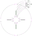
Fig. 2 is a top view of the rotary table of the mechanical clamping tool suitable for the rotary table tapping machine in fig. 1.
Detailed Description
Specific examples of the present invention will be described in further detail below. It should be understood that the description herein of embodiments of the invention is not intended to limit the scope of the invention.
As shown in fig. 1 to fig. 2, it is a schematic structural diagram of a mechanical clamping tool suitable for a rotary table tapping machine provided by the present invention. The mechanical clamping tool suitable for the rotary disc tapping machine comprises a clamping device 10 arranged on a rotary disc and a push rod 20 arranged independently. It is conceivable that the mechanical clamping tool for a rotary disc tapping machine further includes other functional modules, such as an automatic control system, a power supply system, etc., which are well known to those skilled in the art and will not be described herein again.
The clamping device 10 is arranged on the rotary table and can change position along with the rotation of the rotary table. The clamping device 10 includes a base plate 11 fixed on the turntable, a supporting plate 12 fixed on one end of the base plate 11, a fixing plate 13 fixed on the other end of the base plate 11, a movable plate 14 disposed on the fixing plate 13, and a pressing column 15 fixed on the movable plate 14. The bottom plate 11 is fixed on the surface of the rotary table through a fastener, and the fixing direction is the radial direction of the rotary table. The supporting plate 12 is fixed on the bottom plate 11 and is located at one end far away from the circle center of the turntable. The fixed plate 13 is fixed on the bottom plate 11 and is located at one end close to the circle center of the rotary table. The movable plate 14 is disposed on a side of the fixed plate 13 away from the support plate 12 and can slide along the bottom plate 11. The movable plate 14 is rectangular, the cross section of the top far away from the bottom plate 11 is isosceles trapezoid, and the side close to the fixed plate 13 is a short side. The pressing column 15 is a cylinder fixed on the movable plate 14, and includes a column shaft 151 penetrating through the fixed plate 13, a column head 152 located at one end of the column shaft 151, and a spring 153 sleeved on the column shaft 151. The column 151 has one end fixed to the fixed plate 13 and the other end facing the support plate 12, so as to fix a workpiece between the column 152 and the support plate 12. The diameter of the stud 152 is greater than the diameter of the shaft 151. The spring 153 is sleeved on the column body 151 and located between the fixing plate 13 and the column head 152 to generate an elastic force on the pressing column 15 so as to clamp a workpiece placed between the column head 152 and the support plate 12.
The push rod 20 includes a bracket 21 fixed on the ground on one side of the turntable, and a rotary head 22 provided on the bracket 21. The bracket 21 is made of stainless steel or the like and is fixed using a fastener. The rotating head 22 is located at one end of the bracket 21 and extends to the movable plate 14. The rotor 22 is cylindrical and has a thickness corresponding to the height of the isosceles trapezoid of the movable plate 14, so that the rotor 22 slides along the side of the movable plate 14, specifically, on three sides of the isosceles trapezoid close to the fixed plate 13. It is conceivable that when the rotary table is rotated, the stationary rotary head 22 slides along the side surface of the movable plate 14, and slides from the long side to the short side of the isosceles trapezoid in cross section, pushing the movable plate 14 away from the fixed plate 13, and the position of the pressing column 15 fixed to the movable plate 14 changes, so that the distance between the column head 152 and the fixed plate 13 becomes large, thereby facilitating the workpiece placement; accordingly, when the rotary head 22 slides from the short side to the long side of the isosceles trapezoid in cross section, the low pressure column 15 clamps the workpiece by the spring 153.
Compared with the prior art, the utility model provides a machinery clamp dress frock suitable for tooth machine is attacked to carousel fixes on the carousel through setting up one clamping device 10 fixes the work piece, clamping device accomplishes the centre gripping to the work piece through one to the compression leg 15 and fixed plate 13. And a rotary head 22 is arranged on the push rod 20, the movable plate 14 slides on the bottom plate 11 through the position change of the rotary head 22 and the movable plate 14, and further the distance between the pressing column 15 and the fixed plate 13 is driven to change, so that the workpiece is clamped.
The above description is only for the preferred embodiment of the present invention and should not be construed as limiting the scope of the present invention, and any modification, equivalent replacement or improvement within the spirit of the present invention is encompassed by the claims of the present invention.
Claims (8)
1. The utility model provides a machinery presss from both sides dress frock suitable for tooth machine is attacked to carousel which characterized in that: the mechanical clamping tool suitable for the rotary disc tapping machine comprises a clamping device and a push rod, wherein the clamping device is arranged on a rotary disc, the push rod is independently arranged, the clamping device comprises a base plate fixed on the rotary disc, a supporting plate fixed at one end of the base plate, a fixing plate fixed at the other end of the base plate, a movable plate arranged on the fixing plate, and a pressing column fixed on the movable plate, the movable plate is arranged on the fixing plate, the fixing plate is far away from one side of the supporting plate and can slide along the base plate, the pressing column is a cylinder fixed on the movable plate and comprises a column body penetrating through the fixing plate, a column head located at one end of the column body and a spring sleeved on the column body, one end of the column body is fixed on the fixing plate, the other end of the column head faces towards the supporting plate, the spring is sleeved on the column body and located between the fixing plate and the column head, the push rod comprises a support fixed on the ground on one side of the rotary disc and a rotary head arranged on the support, and the rotary head is located at one end of the movable plate.
2. The mechanical clamping tool suitable for the rotary disc tapping machine as claimed in claim 1, wherein: the bottom plate is fixed on the surface of the rotary table through a fastener, and the fixing direction is the radial direction of the rotary table.
3. The mechanical clamping tool suitable for the rotary disc tapping machine as claimed in claim 1, wherein: the supporting plate and the movable plate are fixed on the bottom plate, the supporting plate is located at one end far away from the circle center of the rotary table, and the fixed plate is located at the other end close to the circle center of the rotary table.
4. The mechanical clamping tool suitable for the rotary disc tapping machine as claimed in claim 1, wherein: the movable plate is rectangular block-shaped.
5. The mechanical clamping tool suitable for the rotary disc tapping machine as claimed in claim 4, wherein: the section of the movable plate, which is far away from the top of the bottom plate, is isosceles trapezoid, and the side, which is close to the fixed plate, is a short side.
6. The mechanical clamping tool suitable for the rotary disc tapping machine as claimed in claim 1, wherein: the diameter of the column head is larger than that of the column body.
7. The mechanical clamping tool suitable for the rotary disc tapping machine as claimed in claim 1, wherein: the bracket is made of stainless steel material and is fixed on the ground by using a fastener.
8. The mechanical clamping tool suitable for the rotary disc tapping machine as claimed in claim 1, wherein: the rotary head is cylindrical, and the thickness of the rotary head is consistent with the height of the isosceles trapezoid section of the movable plate.
Priority Applications (1)
| Application Number | Priority Date | Filing Date | Title |
|---|---|---|---|
| CN202221732371.5U CN218657176U (en) | 2022-07-06 | 2022-07-06 | Mechanical clamping tool suitable for rotary table tapping machine |
Applications Claiming Priority (1)
| Application Number | Priority Date | Filing Date | Title |
|---|---|---|---|
| CN202221732371.5U CN218657176U (en) | 2022-07-06 | 2022-07-06 | Mechanical clamping tool suitable for rotary table tapping machine |
Publications (1)
| Publication Number | Publication Date |
|---|---|
| CN218657176U true CN218657176U (en) | 2023-03-21 |
Family
ID=85553547
Family Applications (1)
| Application Number | Title | Priority Date | Filing Date |
|---|---|---|---|
| CN202221732371.5U Active CN218657176U (en) | 2022-07-06 | 2022-07-06 | Mechanical clamping tool suitable for rotary table tapping machine |
Country Status (1)
| Country | Link |
|---|---|
| CN (1) | CN218657176U (en) |
-
2022
- 2022-07-06 CN CN202221732371.5U patent/CN218657176U/en active Active
Similar Documents
| Publication | Publication Date | Title |
|---|---|---|
| CN201313258Y (en) | Fixture used for processing flywheel housing | |
| CN218657176U (en) | Mechanical clamping tool suitable for rotary table tapping machine | |
| CN2923172Y (en) | Plane grinding-turning clamping apparatus | |
| CN210878692U (en) | Blade work piece is from centering fast-assembling anchor clamps | |
| CN218856008U (en) | Welding tool for side wall reinforcing plate of automobile body | |
| CN213616305U (en) | High-speed angle machining clamp | |
| CN213003827U (en) | Processing and positioning device for overlong ultrathin deformable workpiece | |
| CN210703690U (en) | Self-locking clamp | |
| CN211414441U (en) | CNC sheet metal work piece adds clamping apparatus | |
| CN208713461U (en) | A kind of frock clamp of motor turning part | |
| CN205032754U (en) | Chuck is fixed a position to machinery | |
| CN2684990Y (en) | Equipment for processing thin sheets and like components peripheral holes | |
| CN204868243U (en) | Reverse gear and shift cantilever and mill and use anchor clamps | |
| CN210209561U (en) | Pneumatic corner compresses tightly frock | |
| CN217344598U (en) | Double-station efficient numerical control machining hydraulic fixing and clamping tool | |
| CN204868251U (en) | Formula cantilever end face milling anchor clamps of shifting that reverse gear side by side | |
| CN219617216U (en) | Tool clamping fixture capable of being pressed rapidly | |
| CN204868090U (en) | Cantilever positioning fixture of shifting that reverses gear of convenient hoist and mount | |
| CN211361401U (en) | Part side rapid clamping fixture | |
| CN212918565U (en) | A fixed tool that is used for circumference to treat processing product | |
| CN212665371U (en) | Fixing equipment for processing | |
| CN110640488A (en) | Processing clamp for processing workpiece | |
| CN215788179U (en) | Machining positioning device | |
| CN216541948U (en) | Pin shaft milling clamp | |
| CN217394415U (en) | Pneumatic tool clamp |
Legal Events
| Date | Code | Title | Description |
|---|---|---|---|
| GR01 | Patent grant | ||
| GR01 | Patent grant |