CN218640949U - Cabin longitudinal beam of vehicle and vehicle - Google Patents
Cabin longitudinal beam of vehicle and vehicle Download PDFInfo
- Publication number
- CN218640949U CN218640949U CN202223059201.8U CN202223059201U CN218640949U CN 218640949 U CN218640949 U CN 218640949U CN 202223059201 U CN202223059201 U CN 202223059201U CN 218640949 U CN218640949 U CN 218640949U
- Authority
- CN
- China
- Prior art keywords
- tubular beam
- tubular
- vehicle
- cabin
- cover plate
- Prior art date
- Legal status (The legal status is an assumption and is not a legal conclusion. Google has not performed a legal analysis and makes no representation as to the accuracy of the status listed.)
- Active
Links
Images


Abstract
The utility model discloses a cabin longeron and vehicle of vehicle, the cabin longeron of this vehicle includes: a plurality of tubular beams, a plurality of tubular beams connect in order on the upper and lower direction, and a plurality of tubular beams all extend in the front and back direction, all are formed with the cavity in every tubular beam. Therefore, the multiple tubular beams have higher bending rigidity and torsional rigidity, and also have good bearing and supporting capabilities, the buffering and energy absorption can be effectively improved, and the NVH performance and the safety performance of the front end of the vehicle body in the vehicle are integrally improved.
Description
Technical Field
The utility model belongs to the technical field of the automotive technology and specifically relates to an engine room longeron and vehicle of vehicle are related to.
Background
The frame is the most important bearing part in the automobile, the frame longitudinal beam is one of the key parts, the cabin longitudinal beam is arranged at the front end of the automobile body and is the main bearing part at the front part of the automobile body, the cabin longitudinal beam provides a mounting point for the front auxiliary frame, and the power assembly is also arranged on the front auxiliary frame, so that the excitation of the power assembly is transmitted to a driver and a passenger through the path of the power assembly passing through the cabin longitudinal beam, and the safety performance of the whole automobile is seriously influenced by the structure of the cabin longitudinal beam.
SUMMERY OF THE UTILITY MODEL
The utility model discloses aim at solving one of the technical problem that exists among the prior art at least. Therefore, the utility model provides a cabin longeron of vehicle, the cabin longeron of this vehicle can improve the energy-absorbing of buffering, also can improve the rigidity and the mode of the cabin longeron of vehicle to can improve the security performance of NVH performance and automobile body front end in the car.
The utility model discloses a vehicle is further proposed.
According to the utility model discloses cabin longeron of vehicle of first aspect embodiment, cabin longeron of vehicle includes: the pipe beam is connected in order in the up-down direction, and is a plurality of the pipe beam all extends in the front-back direction, and a cavity is formed in each pipe beam.
Therefore, the plurality of tubular beams are sequentially connected in the vertical direction, so that the plurality of tubular beams have high bending rigidity and torsional rigidity, the plurality of tubular beams also have good bearing and supporting capacity, the buffering and energy absorption can be improved, the rigidity and the mode of the cabin longitudinal beam of the vehicle can be improved, and the NVH performance in the vehicle and the safety performance of the front end of the vehicle body can be improved.
According to some embodiments of the invention, a plurality of tubular beams comprise: the first tubular beam, the second tubular beam, the third tubular beam, the fourth tubular beam and the fifth tubular beam are sequentially connected in the up-down direction.
According to some embodiments of the invention, at least two of the first tubular beam, the second tubular beam, the third tubular beam, the fourth tubular beam, and the fifth tubular beam are different in length in a front-to-rear direction.
According to some embodiments of the present invention, the lengths of the first tubular beam, the second tubular beam, the third tubular beam, the fourth tubular beam and the fifth tubular beam in the front-rear direction are d1, d2, d3, d4 and d5, respectively, and d1, d2, d3, d4 and d5 satisfy the following relation: d1: d2: d3: d4: d5= (0.8-1.2): 3-4): 1-2.
According to the utility model discloses a some embodiments, the lateral surface of first tubular beams is provided with first wheelhouse plate fixed part.
According to some embodiments of the utility model, the lateral surface of second tubular beams is provided with spaced second wheel cover plate fixed part and third wheel cover plate fixed part around, second wheel cover plate fixed part first wheel cover plate fixed part with third wheel cover plate fixed part is the protruding form of convex arch that makes progress of shape that the line formed in order.
According to some embodiments of the invention, the first tubular beam is arranged in the middle of the second tubular beam in the length direction; and/or;
the front end of the fourth tubular beam is located behind and below the front end of the third tubular beam and forms a first step with the third tubular beam, and the front end of the fifth tubular beam is located behind and below the front end of the fourth tubular beam and forms a second step with the fourth tubular beam.
According to some embodiments of the invention, the second tubular beam is provided with a first arcuate groove below the first tubular beam; and/or
A second arched groove is formed in the third tubular beam; and/or
A third arched groove is formed in the fourth tubular beam; and/or
And a fourth arched groove is formed in the fifth tubular beam.
According to some embodiments of the invention, the cross-sectional shape of at least two of the tube girders in the nacelle longitudinal beam is different.
According to the utility model discloses vehicle of second aspect embodiment, the vehicle includes: the cabin longitudinal beam of the vehicle.
Additional aspects and advantages of the invention will be set forth in part in the description which follows and, in part, will be obvious from the description, or may be learned by practice of the invention.
Drawings
The above and/or additional aspects and advantages of the present invention will become apparent and readily appreciated from the following description of the embodiments, taken in conjunction with the accompanying drawings of which:
fig. 1 is a schematic structural view of a cabin longitudinal beam of a vehicle according to an embodiment of the present invention;
FIG. 2 is an assembly schematic of a cabin stringer of a vehicle according to an embodiment of the present invention;
fig. 3 is a cut-away schematic view of a cabin stringer of a vehicle according to an embodiment of the present invention;
FIG. 4 isbase:Sub>A cross-sectional view taken along the line A-A in FIG. 3;
FIG. 5 is a cross-sectional view taken along the line B-B in FIG. 3;
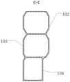
FIG. 6 is a cross-sectional view taken along the line C-C in FIG. 3;
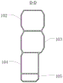
fig. 7 is a sectional view taken along the direction D-D in fig. 3.
Reference numerals:
100. a nacelle stringer;
10. a tubular beam; 101. a first tubular beam; 102. a second tubular beam; 103. a third tubular beam; 104. a fourth tubular beam; 105. a fifth tubular beam;
20. a first wheel house plate fixing portion; 21. a second wheel housing plate fixing portion; 22. a third wheel cover plate fixing part; 23. a wheel cover plate;
30. a first arcuate recess; 31. a second arcuate recess.
Detailed Description
Embodiments of the present invention are described in detail below, and the embodiments described with reference to the drawings are exemplary.
A cabin stringer 100 of a vehicle according to an embodiment of the present invention for carrying components of a vehicle body 100 is described below with reference to fig. 1-7.
As shown in fig. 1, a cabin longitudinal beam 100 of a vehicle according to an embodiment of the present invention includes: a plurality of tubular beams 10, a plurality of tubular beams 10 are connected in order in the upper and lower direction, and a plurality of tubular beams 10 all extend in the front and back direction, all are formed with the cavity in every tubular beam 10.
Specifically, as shown in fig. 1, the plurality of tubular beams 10 are sequentially connected in the vertical direction, so that the plurality of tubular beams 10 are sequentially stacked in the vertical direction, and thus the plurality of tubular beams 10 have higher bending rigidity and torsional rigidity, the plurality of tubular beams 10 also have good bearing and supporting capabilities, and the high rigidity of the plurality of tubular beams 10 in the nacelle longitudinal beam corresponds to a high mode, which can improve a first-order torsional mode of the nacelle longitudinal beam 100, so that the modal frequency of the nacelle longitudinal beam 100 can avoid the working frequency of the whole vehicle and the power assembly, and a frequency avoiding effect is achieved. The plurality of tubular beams 10 extend in the front-rear direction, so that the plurality of tubular beams 10 can be conveniently connected with the components in the front-rear direction in a matched manner. The cavity is formed in each tubular beam 10, so that buffering and energy absorption can be improved, and the NVH performance in a vehicle and the safety performance of the front end of the vehicle body can be improved.
Therefore, the plurality of tubular beams 10 are sequentially connected in the vertical direction, so that the plurality of tubular beams 10 have high bending rigidity and torsional rigidity, the plurality of tubular beams 10 also have good bearing and supporting capabilities, and the buffering and energy absorption can be improved, so that the NVH performance in a vehicle and the safety performance of the front end of the vehicle body can be improved.
According to some embodiments of the present invention, as shown in fig. 1, a plurality of tubular beams 10 includes: the first tubular beam 101, the second tubular beam 102, the third tubular beam 103, the fourth tubular beam 104 and the fifth tubular beam 105 are sequentially connected in the vertical direction. Wherein, first tubular beam 101, second tubular beam 102, third tubular beam 103, fourth tubular beam 104 and fifth tubular beam 105 in a plurality of tubular beams 10 connect in order in upper and lower direction, first tubular beam 101 can set up the middle part above second tubular beam 102, second tubular beam 102 sets up the top at third tubular beam 103, fourth tubular beam 104 and fifth tubular beam 105 are the setting of notch cuttype at the rear side of third tubular beam 103. Therefore, the tubular beams 10 have high bending rigidity and torsional rigidity, the tubular beams 10 also have good bearing and supporting capabilities, and the high rigidity of the tubular beams 10 in the cabin longitudinal beam 100 of the vehicle corresponds to a high mode, so that the working frequency of the whole vehicle and a power assembly can be avoided, and the frequency avoiding effect is achieved.
According to some embodiments of the present invention, as shown in fig. 1, at least two of the first tubular beam 101, the second tubular beam 102, the third tubular beam 103, the fourth tubular beam 104, and the fifth tubular beam 105 are different in length in the front-rear direction. Wherein, at least two of the plurality of tubular beams 10 have different lengths in the front-rear direction, for example, the first tubular beam 101 is set to have the shortest length, and the first tubular beam 101 is placed in the middle above the second tubular beam 102, so that on the premise of meeting the requirements of rigidity and strength, the design of the shorter tubular beam 10 can reduce the use of materials, and also can reduce the cost. The second tubular beam 102 is placed above the third tubular beam 103, the second tubular beam 102 and the third tubular beam 103 are arranged to have the same length, and the second tubular beam 102 and the third tubular beam 103 are arranged to have a longer length in the front-rear direction because the second tubular beam 102 and the third tubular beam 103 serve as the main body of the nacelle stringer 100, so that a larger supporting force can be borne. The fourth tubular beam 104 is arranged on the rear side below the third tubular beam 103, the length of the fourth tubular beam 104 is smaller than that of the third tubular beam 103, the fifth tubular beam 105 is arranged on the rear side below the fourth tubular beam 104, and the length of the fifth tubular beam 105 is smaller than that of the fourth tubular beam 104. In this way, the length difference between the tubular beams 10 can make the tubular beams 10 have different modal frequencies, so that the occurrence of resonance between the tubular beams 10 can be effectively avoided.
According to the embodiment of the present invention, as shown in fig. 1, the lengths of the first tubular beam 101, the second tubular beam 102, the third tubular beam 103, the fourth tubular beam 104, and the fifth tubular beam 105 in the front-rear direction are d1, d2, d3, d4, and d5, respectively, and d1, d2, d3, d4, and d5 satisfy the following relations: d1: d2: d3: d4: d5= (0.8-1.2): 3-4): 1-2. Specifically, at least two of the first tubular beam 101, the second tubular beam 102, the third tubular beam 103, the fourth tubular beam 104, and the fifth tubular beam 105 have different lengths in the front-rear direction, the lengths of the first tubular beam 101, the second tubular beam 102, the third tubular beam 103, the fourth tubular beam 104, and the fifth tubular beam 105 are d1, d2, d3, d4, and d5, respectively, and the ratio of the lengths satisfies the relationship: d1: d2: d3: d4: d5= (0.8-1.2): 3-4): 1, (1-2): 1, the proportion range occupied by the length of the first tubular beam 101 is 0.8-1.2, the proportion range occupied by the length of the second tubular beam 102 is 3-4, the proportion range occupied by the length of the third tubular beam 103 is 3-4, the proportion range occupied by the length of the fourth tubular beam 104 is 1-2, and the proportion occupied by the length of the fifth tubular beam 105 is 1. Thus, the length difference design between the tubular beams 10 can effectively avoid the resonance phenomenon between the tubular beams 10. For example, the first tubular beam 101, the second tubular beam 102, the third tubular beam 103, the fourth tubular beam 104, and the fifth tubular beam 105 have lengths of about 280mm,1015mm, 438mm,304mm in this order, and a length ratio of about 1:3.5:3.5:1.5:1, the length difference design between the tubular beams 10 can effectively avoid the resonance phenomenon between the tubular beams; in addition, on the premise of meeting the requirements of rigidity and strength, due to the design of the shorter tubular beam 10, the material handling can be reduced, and the cost is reduced.
According to some embodiments of the present invention, as shown in fig. 2, the outer side surface of the first tubular beam 101 is provided with a first wheelhouse plate fixing portion 20. The first wheel cover plate fixing portion 20 is used for fixing the wheel cover plate 23, the wheel cover plate 23 is tightly attached to the outer side face of the first tubular beam 101, the first wheel cover plate fixing portion 20 on the outer side face of the first tubular beam 101 is fixedly connected with the wheel cover plate 23 through fasteners, the wheel cover plate 23 is directly connected with the shock absorber, vibration energy at the position is large and is a main force transmission stress area, the first wheel cover plate fixing portion 20 is fixedly connected in a staggered mode through the fasteners, stress concentration can be reduced, the first tubular beam 101 can further strengthen connection between the cabin longitudinal beam 100 and the wheel cover plate 23, and therefore fatigue durability of the cabin longitudinal beam 100 of the vehicle can be improved.
According to the embodiment of the present invention, as shown in fig. 2, the outer side surface of the second tubular beam 102 is provided with a second wheel cover plate fixing portion 21 and a third wheel cover plate fixing portion 22 which are spaced from each other in the front-rear direction, and the shape formed by connecting the second wheel cover plate fixing portion 21, the first wheel cover plate fixing portion 20 and the third wheel cover plate fixing portion 22 in sequence is an upwardly convex arch-shaped protrusion. Specifically, a second wheel cover plate fixing portion 21 and a third wheel cover plate fixing portion 22 are arranged on the outer side surface of the second tubular beam 102 at intervals in the front-rear direction, the second wheel cover plate fixing portion 21 is connected to the front end of the outer side of the second tubular beam 102, the third wheel cover plate fixing portion 22 is connected to the rear end of the outer side of the second tubular beam 102, the second wheel cover plate fixing portion 21 and the third wheel cover plate fixing portion 22 are arranged opposite to the outer side surface away from the second tubular beam 102, and the wheel cover plate 23 can be conveniently and fixedly connected with the outer side surface of the second tubular beam 102. The shape formed by connecting the second wheel cover plate fixing part 21, the first wheel cover plate fixing part 20 and the third wheel cover plate fixing part 22 in sequence is an upward convex arch, the convex part is the first wheel cover plate fixing part 20, and the convex arrangement of the first wheel cover plate fixing part 20 can facilitate the fixed connection with the wheel cover plate 23. In this way, the first, second, and third wheelhouse panel fixing portions 20, 21, and 22 and the first and second tubular beams 101 and 102 form a convex arch-shaped reinforced connection form, and the first, second, and third wheelhouse panel fixing portions 20, 21, and 22 and the first and second tubular beams 101 and 102 are connected in a staggered arrangement, so that stress concentration can be avoided, and meanwhile, excitation energy of a road surface can be dispersed and transmitted conveniently, thereby reducing the vibration sensitivity of the cabin side member 100 of the vehicle. The first, second, and third wheel house panel fixing portions 20, 21, and 22 may be fixing holes to which fasteners are fitted.
According to some embodiments of the present invention, as shown in fig. 1 to 7, the first tubular beam 101 is disposed in the middle of the second tubular beam 102 in the length direction, and since the rigidity of the tubular beam 10 is the weakest in the middle, the first tubular beam 101 can be disposed to not only strengthen the connection with the wheel cover plate 23, but also connect with other tubular beams 10. The front end of the fourth tubular beam 104 is located behind and below the front end of the third tubular beam 103, a first step is formed between the front end of the fourth tubular beam 104 and the third tubular beam 103, the front end of the fifth tubular beam 105 is located behind and below the front end of the fourth tubular beam 104, and a second step is formed between the front end of the fifth tubular beam 105 and the fourth tubular beam 104. The first tubular beam 101 is arranged in the middle of the second tubular beam 102 in the length direction, the third tubular beam 103 and the fourth tubular beam 104 are arranged below the second tubular beam 102, the front end of the fourth tubular beam 104 is positioned behind and below the front end of the third tubular beam 103, a first step is formed between the fourth tubular beam 104 and the third tubular beam 103, the front end of the fifth tubular beam 105 is positioned behind and below the front end of the fourth tubular beam 104, a second step is formed between the fifth tubular beam 105 and the fourth tubular beam 104, and the sections of the plurality of tubular beams 10 from top to bottom perpendicular to the front-back direction are in a trapezoid shape from wide to narrow, so that the rigidity of the cabin longitudinal beam 100 of the vehicle can be improved, and the supporting capability of the cabin longitudinal beam 100 of the vehicle can also be improved.
According to some embodiments of the present invention, as shown in fig. 1, the second tubular beam 102 is provided with the first arched groove 30 below the first tubular beam 101, and the arched groove strengthening design is designed at the middle position of the second tubular beam 102, i.e. below the first tubular beam 101, and the length (front-back direction) and the depth (inside-outside direction) of the first arched groove 30 can be set according to the actual size of the second tubular beam 102, so as to have good adaptability. For example, the length of the first arcuate groove 30 is about 150mm, and the depth of the first arcuate groove 30 is up to 10mm. Further, a plurality of tubular beams 10 may be provided with corresponding grooves, and the grooves of the plurality of tubular beams 10 are spaced apart, for example, a third tubular beam 103 may be provided with a second arched groove 31, for example, the length of the second arched groove 31 is about 57mm, and the depth of the second arched groove 31 is up to 5mm. A third arched groove is arranged on the fourth tubular beam 104, and a fourth arched groove is arranged on the fifth tubular beam 105. The reinforced design of the arched grooves can improve the rigidity of the cabin longitudinal beam 100 of the vehicle, and can also strengthen the support of the cabin longitudinal beam 100 of the vehicle on the wheel cover plate 23, thereby facilitating the dispersion and transmission of stress.
According to some embodiments of the present invention, the cabin longitudinal beam 100 of the vehicle is an integrally formed aluminum alloy profile, and the cross-sectional shapes of at least two tubular beams 10 in the cabin longitudinal beam 100 are different. The density of the aluminum alloy section is greatly lower than that of steel, the aluminum alloy section is lighter under the same volume, the structural strength and rigidity are not greatly different, the selection of the aluminum alloy section greatly reduces the weight of the whole vehicle, and the aim of lightweight design is fulfilled; in addition, the aluminum alloy section is easier to form, and can support the production of a more complex longitudinal beam structure. And the integrally formed aluminum alloy section greatly reduces the number of longitudinal beam parts, reduces the welding cost of vehicles, improves the welding efficiency and saves the cost. Moreover, since at least two of the plurality of tubular members 10 have different lengths and/or at least two of the plurality of tubular members have different cross-sectional shapes, the cross-sectional shape of the entire nacelle side member 100 is different at a plurality of positions in the front-rear direction, and the change in the cross-sectional shape is advantageous for reducing noise radiation excited by the powertrain and the road surface, so that the noise level in the vehicle can be improved.
According to the utility model discloses vehicle of second aspect embodiment includes: a cabin stringer 100 of a vehicle.
In the description herein, references to the description of the term "one embodiment," "some embodiments," "an illustrative embodiment," "an example," "a specific example," or "some examples" or the like mean that a particular feature, structure, material, or characteristic described in connection with the embodiment or example is included in at least one embodiment or example of the present invention. In this specification, the schematic representations of the terms used above do not necessarily refer to the same embodiment or example.
While embodiments of the present invention have been shown and described, it will be understood by those of ordinary skill in the art that: various changes, modifications, substitutions and alterations can be made to the embodiments without departing from the principles and spirit of the invention, the scope of which is defined by the claims and their equivalents.
Claims (10)
1. A cabin stringer for a vehicle, comprising: the pipe beam is connected in order in the up-down direction, and is a plurality of the pipe beam all extends in the front-back direction, and a cavity is formed in each pipe beam.
2. The vehicle cabin stringer of claim 1, wherein a plurality of said tubular beams comprise: the first tubular beam, the second tubular beam, the third tubular beam, the fourth tubular beam and the fifth tubular beam are sequentially connected in the up-down direction.
3. The cabin stringer of a vehicle according to claim 2, wherein at least two of the first tubular beam, the second tubular beam, the third tubular beam, the fourth tubular beam, and the fifth tubular beam differ in length in a front-rear direction.
4. The cabin stringer of a vehicle according to claim 3, wherein lengths of the first tubular beam, the second tubular beam, the third tubular beam, the fourth tubular beam, and the fifth tubular beam in the front-rear direction are d1, d2, d3, d4, and d5, respectively, and d1, d2, d3, d4, and d5 satisfy the relationship: d1: d2: d3: d4: d5= (0.8-1.2): 3-4: 1-2).
5. The cabin side member for a vehicle according to claim 2, wherein an outer side surface of the first tubular member is provided with a first cowl panel fixing portion.
6. The vehicle cabin longitudinal beam of claim 5, wherein a second wheel cover plate fixing portion and a third wheel cover plate fixing portion are arranged on the outer side surface of the second tubular beam at intervals in the front-rear direction, and the shape formed by connecting the second wheel cover plate fixing portion, the first wheel cover plate fixing portion and the third wheel cover plate fixing portion in sequence is an upwardly convex arch-shaped bulge shape.
7. The cabin stringer of claim 2, wherein said first tubular beam is disposed at a middle of said second tubular beam in a lengthwise direction; and/or;
the front end of the fourth tubular beam is positioned behind and below the front end of the third tubular beam and forms a first step with the third tubular beam, and the front end of the fifth tubular beam is positioned behind and below the front end of the fourth tubular beam and forms a second step with the fourth tubular beam.
8. The cabin stringer of a vehicle of claim 2, wherein said second tubular beam is provided with a first arcuate groove below said first tubular beam; and/or
A second arched groove is formed in the third tubular beam; and/or
A third arched groove is formed in the fourth tubular beam; and/or
And a fourth arched groove is formed in the fifth tubular beam.
9. The vehicle cabin stringer according to claim 1, wherein at least two of said cabin stringers have different cross-sectional shapes.
10. A vehicle, characterized by comprising: a cabin stringer for a vehicle according to any of claims 1-9.
Priority Applications (1)
| Application Number | Priority Date | Filing Date | Title |
|---|---|---|---|
| CN202223059201.8U CN218640949U (en) | 2022-11-17 | 2022-11-17 | Cabin longitudinal beam of vehicle and vehicle |
Applications Claiming Priority (1)
| Application Number | Priority Date | Filing Date | Title |
|---|---|---|---|
| CN202223059201.8U CN218640949U (en) | 2022-11-17 | 2022-11-17 | Cabin longitudinal beam of vehicle and vehicle |
Publications (1)
| Publication Number | Publication Date |
|---|---|
| CN218640949U true CN218640949U (en) | 2023-03-17 |
Family
ID=85498881
Family Applications (1)
| Application Number | Title | Priority Date | Filing Date |
|---|---|---|---|
| CN202223059201.8U Active CN218640949U (en) | 2022-11-17 | 2022-11-17 | Cabin longitudinal beam of vehicle and vehicle |
Country Status (1)
| Country | Link |
|---|---|
| CN (1) | CN218640949U (en) |
-
2022
- 2022-11-17 CN CN202223059201.8U patent/CN218640949U/en active Active
Similar Documents
| Publication | Publication Date | Title |
|---|---|---|
| RU2550401C2 (en) | Car body structure | |
| CN103786788B (en) | A kind of automobile front subframe and corresponding automobile | |
| CN115214788A (en) | Automobile lower body structure and automobile | |
| CN115066366A (en) | Rear damping tower, rear damping tower assembly and vehicle | |
| CN218640949U (en) | Cabin longitudinal beam of vehicle and vehicle | |
| CN116161119A (en) | Aluminum auxiliary frame of electric car | |
| CN214001840U (en) | Ventilation cover plate assembly and vehicle | |
| CN213566147U (en) | Rear wheel cover reinforcing structure and vehicle | |
| CN218640948U (en) | Cabin longeron assembly and vehicle | |
| CN219749961U (en) | Rear floor structure, vehicle body assembly and vehicle | |
| CN112441126A (en) | Front body structure of vehicle | |
| CN220842705U (en) | Front cabin stabilizing cross beam, front cabin structure of vehicle and vehicle | |
| CN219838625U (en) | Vehicle with a vehicle body having a vehicle body support | |
| CN217170508U (en) | Single beam type two-row seat supporting structure | |
| CN114228418B (en) | Body structure of hovercar and hovercar | |
| CN220374635U (en) | Automobile top cover and automobile with same | |
| CN220785929U (en) | Reinforcing device and vehicle | |
| CN219447147U (en) | Middle floor assembly, floor assembly and vehicle | |
| CN219467861U (en) | Front floor assembly of vehicle body and vehicle | |
| CN219948349U (en) | Vehicle body assembly and vehicle | |
| CN218703535U (en) | Well rear floor assembly and vehicle | |
| CN220483417U (en) | Front engine room structure and automobile | |
| CN212373513U (en) | Reinforcing component of vehicle rear wheel cover and vehicle | |
| CN217863594U (en) | Top cover structure and aerocar | |
| CN218431430U (en) | Automobile body rear portion assembly structure and car |
Legal Events
| Date | Code | Title | Description |
|---|---|---|---|
| GR01 | Patent grant | ||
| GR01 | Patent grant |