CN218613946U - A mould clamping device for mould processing - Google Patents
A mould clamping device for mould processing Download PDFInfo
- Publication number
- CN218613946U CN218613946U CN202222918476.6U CN202222918476U CN218613946U CN 218613946 U CN218613946 U CN 218613946U CN 202222918476 U CN202222918476 U CN 202222918476U CN 218613946 U CN218613946 U CN 218613946U
- Authority
- CN
- China
- Prior art keywords
- baffle
- mould
- clamping device
- mold
- support column
- Prior art date
- Legal status (The legal status is an assumption and is not a legal conclusion. Google has not performed a legal analysis and makes no representation as to the accuracy of the status listed.)
- Active
Links
Images


Classifications
-
- Y—GENERAL TAGGING OF NEW TECHNOLOGICAL DEVELOPMENTS; GENERAL TAGGING OF CROSS-SECTIONAL TECHNOLOGIES SPANNING OVER SEVERAL SECTIONS OF THE IPC; TECHNICAL SUBJECTS COVERED BY FORMER USPC CROSS-REFERENCE ART COLLECTIONS [XRACs] AND DIGESTS
- Y02—TECHNOLOGIES OR APPLICATIONS FOR MITIGATION OR ADAPTATION AGAINST CLIMATE CHANGE
- Y02P—CLIMATE CHANGE MITIGATION TECHNOLOGIES IN THE PRODUCTION OR PROCESSING OF GOODS
- Y02P40/00—Technologies relating to the processing of minerals
- Y02P40/50—Glass production, e.g. reusing waste heat during processing or shaping
- Y02P40/57—Improving the yield, e-g- reduction of reject rates
Landscapes
- Moulds For Moulding Plastics Or The Like (AREA)
Abstract
The utility model discloses a mould clamping device for mould processing relates to a mould processing field, be provided with the support column including the base top, the support column outside is provided with first removal axle, and first removal axle inboard is provided with the second and removes the axle, and second removal axle one side is provided with second adjustment handle, and second removal axle one side is provided with spacing dish, and second removal axle one side is provided with first baffle, and first baffle one side is provided with the second baffle, and second baffle bottom is provided with the third baffle, and third baffle bottom is provided with the fourth baffle, and fourth baffle top sets up the mould that remains to process. The utility model discloses a set up the sleeve and be fixed in different locating holes, reach the purpose of adjusting device height, be applicable to the mould of co-altitude not, peg graft with different fixed slots through setting up the bolt, can adjust the rotation angle that the second removed the axle, can be suitable for with the mould of co-ordinate-angle.
Description
Technical Field
The utility model relates to a mould processing field, in particular to mould clamping device for mould processing.
Background
For example, in a mold clamping device (application number: CN 202121700545.5) for mold processing, the design of the mold clamping device is reasonable, when in use, the bottom frame is moved by matching of a pushing handle and a caster wheel, the device is moved to the outer side of a mold to be clamped, then a switch is used for controlling a motor to start working, so that the height position of a moving plate is adjusted, the bottom frame is inserted into the bottom of a mold processing table, guide wheels and flexible ring sleeves at two ends of a clamping frame play a role in guiding the end part of the clamping frame, the end part of the clamping frame is prevented from directly impacting on the mold, then a switch is used for controlling an electric cylinder to start working, the electric cylinder drives an electric clamping plate to clamp the mold, meanwhile, the clamping plate drives a supporting plate to move to the lower part of the mold to form lifting, at the time, a guide rod plays a role in guiding and supporting the clamping plate to finish the clamping work of the mold, but the size of the mold cannot be adjusted, and the use of molds with different sizes cannot be convenient for mold processing the inclined surface is necessary.
SUMMERY OF THE UTILITY MODEL
An object of the utility model is to provide a mould clamping device for mould processing to the size of the not adjustable mould that provides in solving above-mentioned background art, not the not unidimensional mould in service problem of being convenient for.
In order to achieve the above object, the utility model provides a following technical scheme: the utility model provides a mould clamping device for mould processing, includes the base, the base top is provided with the support column, the support column outside is provided with first removal axle, first removal inboard is provided with the second and removes the axle, second removal axle one side is provided with the second and adjusts the handle, second removal axle one side is provided with spacing dish, second removal axle one side is provided with first baffle, first baffle one side is provided with the second baffle, second baffle bottom is provided with the third baffle, third baffle bottom is provided with the fourth baffle, fourth baffle top sets up the mould that remains to be processed.
Preferably, a sleeve is arranged outside the supporting column and fixedly connected with the supporting column.
Preferably, the top of the support column is provided with a limit block, and the support column is fixedly connected with the limit block.
Preferably, the top of the support column is provided with a limit block, and the support column is fixedly connected with the limit block.
Preferably, the top of the first moving shaft is provided with a bolt, the second moving shaft is internally provided with a fixed groove, and the first moving shaft and the second moving shaft are fixedly connected with the fixed groove through the bolt.
Preferably, the top of the second baffle is provided with a first fixing screw, the bottom of the second baffle is provided with an adjusting shaft, and the second baffle is fixedly connected with the adjusting shaft through the first fixing screw.
Preferably, the bottom of the adjusting shaft is provided with a gasket, the top of the gasket is provided with a second fixing screw, and the adjusting shaft and the third baffle are fixedly connected with the second fixing screw through the gasket.
The utility model discloses a technological effect and advantage:
1. according to the die clamping device for die machining, the purpose of adjusting the height of the device is achieved by arranging the sleeves to be fixed in different positioning holes, and the die clamping device is suitable for dies with different heights;
2. according to the mold clamping device for mold processing, the plug pins are arranged to be inserted into different fixing grooves, so that the rotation angle of the second moving shaft can be adjusted, and the mold clamping device can be suitable for molds with different angles;
3. this a mould clamping device for mould processing through the height that sets up the regulating spindle, can adjust the distance between second baffle and the third baffle to make and can put down not unidimensional mould between third baffle and the fourth baffle, be suitable for with not unidimensional mould, improve device's utilization ratio.
Drawings
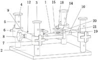
Fig. 1 is a front schematic view of a mold clamping device structure for mold processing of the present invention.
Fig. 2 is a schematic view of the top view of the structure of the mold clamping device for mold processing of the present invention.
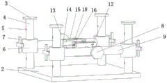
Fig. 3 is a schematic side view of the structure of the mold clamping device for mold processing of the present invention.
Fig. 4 is a schematic bottom view of the structure of the mold clamping device for mold processing of the present invention.
In the figure: 1. a mold to be processed; 2. a base; 3. a limiting block; 4. a support column; 5. positioning holes; 6. a sleeve; 7. a first adjustment handle; 8. a second adjustment handle; 9. a first moving axis; 10. a second moving axis; 11. fixing grooves; 12. plugging; 13. a limiting disc; 14. a first baffle plate; 15. a second baffle; 16. a third baffle plate; 17. a fourth baffle; 18. a first fixing screw; 19. a gasket; 20. an adjustment shaft; 21. and a second fixing screw.
Detailed Description
The technical solutions in the embodiments of the present invention will be described clearly and completely with reference to the accompanying drawings in the embodiments of the present invention, and it is obvious that the described embodiments are only some embodiments of the present invention, not all embodiments. Based on the embodiments in the present invention, all other embodiments obtained by a person skilled in the art without creative work belong to the protection scope of the present invention.
The utility model provides a mould clamping device for mould processing as shown in fig. 1-4, a mould clamping device for mould processing, including base 2, base 2 top is provided with support column 4, support column 4 outside is provided with first removal axle 9, first removal axle 9 inboard is provided with the second and removes axle 10, second removal axle 10 one side is provided with second regulation handle 8, second removal axle 10 one side is provided with spacing dish 13, second removal axle 10 one side is provided with first baffle 14, first baffle 14 one side is provided with second baffle 15, second baffle 15 bottom is provided with third baffle 16, third baffle 16 bottom is provided with fourth baffle 17, fourth baffle 17 top sets up the mould 1 that remains to process.
In this embodiment, as the preferred technical scheme of the utility model, 4 outsides of support column are provided with sleeve 6, and sleeve 6 is provided with first regulation handle 7 outward, and sleeve 6 is through first regulation handle 7 and 4 fixed connection of support column.
As the utility model discloses an optimal technical scheme, locating hole 5 has been seted up to support column 4 is inside, and first regulation handle 7 connects soon through locating hole 5 and support column 4.
As the utility model discloses an optimal technical scheme, 4 tops of support column are provided with stopper 3, support column 4 and stopper 3 fixed connection.
As the utility model discloses a preferred technical scheme, first removal axle 9 top is provided with plug 12, and the second removes axle 10 inside and has seted up fixed slot 11, removes axle 10 with first removal axle 9 and second and passes through plug 12 and fixed slot 11 fixed connection.
As the utility model discloses an optimal technical scheme, second baffle 15 top is provided with first fixed screw 18, and 15 bottoms of second baffle are provided with regulating spindle 20, and second baffle 15 passes through 18 fixed connection of first fixed screw with regulating spindle 20.
As the preferred technical scheme of the utility model, regulating spindle 20 bottom is provided with gasket 19, and 19 tops of gasket are provided with second fixed screw 21, and regulating spindle 20 passes through gasket 19 and second fixed screw 21 fixed connection with third baffle 16.
The working principle is as follows: this a mould clamping device for mould processing when using, the user is through setting up the fixed degree of first regulation handle 7, make sleeve 6 reciprocate, connect soon through adjustment first regulation handle 7 and locating hole 5, make sleeve 6 be fixed in different positions on the locating hole 5, reach the purpose of adjusting device height, be applicable to the mould of co-altitude not, the user is pegged graft 11 through setting up plug 12 and different fixed slots, can adjust the rotation angle that the second removed axle 10, can be suitable for and the mould of co-altitude not, the user is through setting up the height of regulating spindle 20, can adjust the distance between second baffle 15 and the third baffle 16, make third baffle 16, can put down not unidimensional mould between the fourth baffle 17, be suitable for and not co-altitude's mould, the utilization ratio of device is improved.
Claims (7)
1. A mould clamping device for mould processing, includes base (2), its characterized in that: the processing fixture is characterized in that a supporting column (4) is arranged at the top of the base (2), a first moving shaft (9) is arranged outside the supporting column (4), a second moving shaft (10) is arranged on the inner side of the first moving shaft (9), a second adjusting handle (8) is arranged on one side of the second moving shaft (10), a limiting disc (13) is arranged on one side of the second moving shaft (10), a first baffle (14) is arranged on one side of the second moving shaft (10), a second baffle (15) is arranged on one side of the first baffle (14), a third baffle (16) is arranged on the bottom of the second baffle (15), a fourth baffle (17) is arranged on the bottom of the third baffle (16), and a mold (1) to be processed is arranged at the top of the fourth baffle (17).
2. The mold clamping device for mold tooling of claim 1, wherein: the support column (4) outside is provided with sleeve (6), sleeve (6) are provided with first regulation handle (7) outward, sleeve (6) are through first regulation handle (7) and support column (4) fixed connection.
3. A mold clamping device for mold tooling as set forth in claim 2 wherein: the support column (4) is internally provided with a positioning hole (5), and the first adjusting handle (7) is connected with the support column (4) in a rotating mode through the positioning hole (5).
4. A mold clamping device for mold tooling as set forth in claim 3 wherein: the top of the support column (4) is provided with a limiting block (3), and the support column (4) is fixedly connected with the limiting block (3).
5. The mold clamping device for mold tooling of claim 1, wherein: the top of the first moving shaft (9) is provided with a bolt (12), a fixing groove (11) is formed in the second moving shaft (10), and the first moving shaft (9) and the second moving shaft (10) are fixedly connected with the fixing groove (11) through the bolt (12).
6. The mold clamping device for mold tooling of claim 1, wherein: the top of the second baffle plate (15) is provided with a first fixing screw (18), the bottom of the second baffle plate (15) is provided with an adjusting shaft (20), and the second baffle plate (15) is fixedly connected with the adjusting shaft (20) through the first fixing screw (18).
7. The mold clamping device for mold tooling as set forth in claim 6, wherein: adjusting shaft (20) bottom is provided with gasket (19), gasket (19) top is provided with second fixed screw (21), adjusting shaft (20) and third baffle (16) pass through gasket (19) and second fixed screw (21) fixed connection.
Priority Applications (1)
| Application Number | Priority Date | Filing Date | Title |
|---|---|---|---|
| CN202222918476.6U CN218613946U (en) | 2022-10-31 | 2022-10-31 | A mould clamping device for mould processing |
Applications Claiming Priority (1)
| Application Number | Priority Date | Filing Date | Title |
|---|---|---|---|
| CN202222918476.6U CN218613946U (en) | 2022-10-31 | 2022-10-31 | A mould clamping device for mould processing |
Publications (1)
| Publication Number | Publication Date |
|---|---|
| CN218613946U true CN218613946U (en) | 2023-03-14 |
Family
ID=85423381
Family Applications (1)
| Application Number | Title | Priority Date | Filing Date |
|---|---|---|---|
| CN202222918476.6U Active CN218613946U (en) | 2022-10-31 | 2022-10-31 | A mould clamping device for mould processing |
Country Status (1)
| Country | Link |
|---|---|
| CN (1) | CN218613946U (en) |
-
2022
- 2022-10-31 CN CN202222918476.6U patent/CN218613946U/en active Active
Similar Documents
| Publication | Publication Date | Title |
|---|---|---|
| CN215357305U (en) | Quick clamping frock of digit control machine tool | |
| CN218613946U (en) | A mould clamping device for mould processing | |
| CN217749511U (en) | Circular ring vertical movable column slot milling machine | |
| CN215236938U (en) | High-precision transmission shaft straightening device | |
| CN213164645U (en) | Grinding device for batch head processing | |
| CN219726177U (en) | Rotary tool clamp for injection mold machining | |
| CN220427851U (en) | Adjustable miniature polishing device | |
| CN218658155U (en) | Corner grinding device | |
| CN218696345U (en) | Anchor clamps convenient to mould inclined plane processing | |
| CN220863566U (en) | Angle-adjustable polishing device | |
| CN114918692B (en) | Placing device for part machining | |
| CN217571172U (en) | Steel plate fixing device for tapping machine | |
| CN212287057U (en) | Automatic feeding mechanism for grinding machine machining | |
| CN217344543U (en) | A centre gripping equipment for spare part | |
| CN218965217U (en) | Adjusting and fixing device for machining rim | |
| CN220408683U (en) | Adjustable workbench for machining automobile die | |
| CN219169400U (en) | Stamping forming die | |
| CN219310743U (en) | Elbow joint machined part | |
| CN217858850U (en) | Annular product end face machining device | |
| CN220279150U (en) | Device for removing burrs in hub processing | |
| CN211662236U (en) | Fixing device for router | |
| CN219293567U (en) | Die cavity polishing machine for die casting mold | |
| CN220162102U (en) | Mechanical casting processing angle grinder | |
| CN216359527U (en) | Machining device for automobile engine accessory die | |
| CN216859002U (en) | Frock clamp of accurate alloy processing |
Legal Events
| Date | Code | Title | Description |
|---|---|---|---|
| GR01 | Patent grant | ||
| GR01 | Patent grant |