CN218606373U - Electric handheld ground cleaning machine - Google Patents
Electric handheld ground cleaning machine Download PDFInfo
- Publication number
- CN218606373U CN218606373U CN202022383918.2U CN202022383918U CN218606373U CN 218606373 U CN218606373 U CN 218606373U CN 202022383918 U CN202022383918 U CN 202022383918U CN 218606373 U CN218606373 U CN 218606373U
- Authority
- CN
- China
- Prior art keywords
- gear
- assembly
- brush
- component
- water tank
- Prior art date
- Legal status (The legal status is an assumption and is not a legal conclusion. Google has not performed a legal analysis and makes no representation as to the accuracy of the status listed.)
- Active
Links
Images


Abstract
The utility model discloses an electric hand-held floor cleaning machine, which comprises a handle component, a connecting component, a face shell component, a right brush component, a left brush component, a water tank atomizing component, a garbage box component and a cleaning component; the handle assembly is arranged on the face shell assembly through the connecting assembly; the bottom of the bottom shell assembly is symmetrically provided with a right brush assembly and a left brush assembly which are used for cleaning the ground and have the same structure, and the bottom of the bottom shell assembly is also provided with a cleaning assembly; one side of the bottom shell assembly is provided with a water tank atomization assembly for mopping the floor; a garbage box assembly used for collecting dust is arranged on one side of the interior of the bottom shell assembly. The utility model discloses simple structure, and the volume is less, is fit for clearing up narrow and small region, through brush group subassembly on the left side, the brush group subassembly on the right, clean the cooperation of subassembly and water tank atomization component, not only can clear up ground, can drag the ground moreover, wax to clean efficiency has been improved.
Description
Technical Field
The utility model relates to a cleaning machine, in particular to an electric handheld ground cleaning machine.
Background
Floor cleaning machines are domestic appliances that automatically clean the floor. Most of current ground cleaning machines, its structure is comparatively complicated, and the volume is great, and the resident is when cleaning indoor, comparatively labouring when cleaning narrow and small place, and the ground cleaning machine can only clean ground, can't drag ground to ground.
SUMMERY OF THE UTILITY MODEL
An object of the utility model is to provide an electronic handheld ground cleaning machine to solve the problem that proposes among the above-mentioned background art.
In order to achieve the above object, the utility model provides a following technical scheme:
an electric hand-held floor cleaning machine comprises a handle assembly, a connecting assembly, a face shell assembly, a right brush assembly, a left brush assembly, a water tank atomization assembly, a garbage box assembly and a cleaning assembly; the handle assembly is arranged on the face shell assembly through the connecting assembly; the bottom of the face shell component is symmetrically provided with a right brush group component and a left brush group component which are used for cleaning the ground and have the same structure, and the bottom of the face shell component is also provided with a cleaning component; one side of the face shell component is provided with a water tank atomization component for mopping the floor; a garbage box assembly used for collecting dust is arranged on one side of the interior of the face shell assembly.
As a further aspect of the present invention: the handle assembly comprises a handle, a spray key, a remote control key board and a key battery; the handle is provided with a spraying button for controlling the water tank atomization assembly to work, the spraying button is arranged on a remote control button plate, and a button battery for supplying power is arranged on the remote control button plate; the lower end of the handle is connected with the connecting component.
As a further aspect of the present invention: the connecting assembly comprises an aluminum alloy circular tube and a push switch; the upper end of the aluminum alloy circular tube is detachably matched and connected with the lower end of the handle, and the aluminum alloy circular tube is provided with a push switch for controlling the aluminum alloy circular tube to stretch; and the lower end surface shell components of the aluminum alloy circular tubes are connected.
As a further aspect of the present invention: the face shell assembly comprises a switching connecting rod, a connecting sleeve, a power switch, a face shell, a main board and a lithium battery; the upper end of the switching connecting rod is detachably matched and connected with the lower end of the aluminum alloy circular tube, and the lower end of the switching connecting rod is connected with the face shell through a connecting sleeve; the power switch for controlling the machine to work is arranged on the face shell, and the main board and the lithium battery for supplying power are arranged in the face shell.
As a further aspect of the present invention: the right brush assembly comprises a right brush upper cover, a first motor, a worm, a second gear, a third gear, a first bearing, a right brush lower cover, a side brush turntable, a first magic tape and a cloth wheel; the right brush upper cover is fixed at the bottom of the bottom shell, and a first motor is fixed in the right brush upper cover; a worm is fixed at the rotating end of the first motor; the second gear matched with the worm is rotatably arranged in the right brush upper cover; a third gear meshed with the second gear is further rotatably arranged in the right brush upper cover; a first bearing is fixed on one side of the bottom of the third gear, a side brush rotating disc is fixed on the bottom of the third gear, and a first magic tape is fixed on the side brush rotating disc; a cloth wheel for cleaning soil on the ground is stuck on the first magic tape; the lower end of the right brush upper cover is detachably matched with a right brush lower cover.
As a further aspect of the present invention: the water tank atomization assembly comprises a silica gel cover, a sealing silica gel ring, a water tank, an atomizing nozzle and an atomizing gland; the water tank for storing water is arranged at the bottom of the bottom shell, a water inlet is formed in the upper end of the water tank, a sealing silica gel ring is arranged on the water inlet, and a silica gel cover is arranged on the sealing silica gel ring in a sealing mode; one side of the bottom of the water tank is provided with a spray nozzle for atomizing water; and a spray gland used for fixing the spray nozzle is arranged on the water tank.
As a further aspect of the present invention: the garbage box assembly comprises a bottom shell and a garbage box; a garbage box used for collecting garbage is placed in the bottom shell, and the bottom shell and the face shell can be detachably fixed.
As a further aspect of the present invention: the sweeping assembly comprises a second bearing, a middle sweeping bracket, a dustpan bar, a middle sweeping brush, a middle sweeping upper cover, a third bearing, a fourth gear, a fifth gear, a sixth gear, a first gear, a middle sweeping lower cover, a second motor, a second magic tape and a mop cloth; the second motor is fixed at the bottom of the bottom shell, and a middle sweeping upper cover and a middle sweeping lower cover which are matched with each other are also fixed on the bottom shell; a fourth gear, a fifth gear, a sixth gear and a first gear are rotatably arranged in the middle sweeping upper cover and the middle sweeping lower cover, and the fourth gear, the fifth gear, the sixth gear and the first gear are meshed in sequence; the first gear is connected with the rotating end of the second motor, the fourth gear is provided with a third bearing, and the fourth gear is connected with one end of the middle sweeping brush; the middle sweeping brush is provided with a dustpan bar, and the other end of the middle sweeping brush is provided with a second bearing; the second bearing is arranged on the middle sweeping support, and the middle sweeping support is fixed on the bottom shell.
Compared with the prior art, the beneficial effects of the utility model are that: the utility model discloses simple structure, and the volume is less, is fit for clearing up narrow and small region, through the left side brush group subassembly, the right brush group subassembly, clean the cooperation of subassembly and water tank atomization component, not only can clear up ground, can drag the ground moreover, wax to clean efficiency has been improved.
Drawings
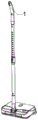
FIG. 1 is a schematic view of a power hand-held floor cleaning machine.
Fig. 2 is an exploded view of the power hand-held floor cleaning machine.
Fig. 3 is a schematic view of the handle assembly of fig. 2.
Fig. 4 is a schematic structural view of the connecting assembly in fig. 2.
Fig. 5 is a schematic structural view of the panel assembly of fig. 2.
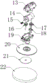
FIG. 6 is a schematic view of the right brush set assembly of FIG. 2.
Fig. 7 is a schematic structural diagram of the water tank atomizing assembly in fig. 2.
Fig. 8 is a schematic structural view of the garbage can assembly in fig. 2.
Fig. 9 is a schematic structural view of the sweeping assembly in fig. 2.
Fig. 10 is a schematic structural view of the left brush set assembly in fig. 2.
In the figure: 1. a handle; 2. spraying a key; 3. a remote control key board; 4. a key battery; 5. an aluminum alloy round tube; 6. a push switch; 7. a transfer connecting rod; 8. connecting sleeves; 9. a power switch; 10. a face shell; 11. a main board; 12. a lithium battery; 13. brushing an upper cover on the right side; 14. a first motor; 15. a worm; 16. a second gear; 17. a third gear; 18. a first bearing; 19. brushing a lower cover on the right; 20. brushing the turntable at the edge; 21. a first magic tape; 22. a cloth wheel; 23. a silicone cover; 24. sealing the silica gel ring; 25. a water tank; 26. a spray nozzle; 27. spraying and capping; 28. a left brush set assembly; 29. a bottom case; 30. a trash box; 31. a second bearing; 32. a middle sweeping bracket; 33. a dustpan bar; 34. a middle sweeping brush; 35. a middle sweeping upper cover; 36. a third bearing; 37. a fourth gear; 38. a fifth gear; 39. a sixth gear; 40. a first gear; 41. a middle sweeping lower cover; 42. a second motor; 43. a second magic tape; 44. and (4) mopping.
Detailed Description
The technical solution of the present patent will be further described in detail with reference to the following embodiments.
Example 1
Referring to fig. 1-10, the present embodiment provides an electric handheld floor cleaning machine, which includes a handle assembly, a connecting assembly, a surface housing assembly, a right brush assembly, a left brush assembly 28, a water tank atomizing assembly, a garbage box assembly, and a sweeping assembly; the handle assembly is arranged on the face shell assembly through the connecting assembly; the bottom of the face shell component is symmetrically provided with a right brush group component and a left brush group component 28 which are used for cleaning the ground and have the same structure, and the bottom of the face shell component is also provided with a cleaning component; one side of the face shell component is provided with a water tank atomization component for mopping the floor; a garbage box assembly used for collecting dust is arranged on one side of the interior of the face shell assembly.
The handle assembly comprises a handle 1, a spray button 2, a remote control button plate 3 and a button battery 4; the handle 1 is provided with a spraying button 2 for controlling the water tank atomization assembly to work, the spraying button 2 is arranged on a remote control button plate 3, and a button battery 4 for supplying power is arranged on the remote control button plate 3; the lower end of the handle 1 is connected with the connecting component.
The connecting assembly comprises an aluminum alloy circular tube 5 and a push switch 6; the upper end of the aluminum alloy circular tube 5 is detachably matched and connected with the lower end of the handle 1, and the aluminum alloy circular tube 5 is provided with a push switch 6 for controlling the aluminum alloy circular tube to stretch; the lower end surface shell components of the aluminum alloy circular tube 5 are connected; set up like this, can adjust the length of aluminum alloy pipe 5 through push switch 6 to satisfy different crowds' demand.
The face shell component comprises a switching connecting rod 7, a connecting sleeve 8, a power switch 9, a face shell 10, a main board 11 and a lithium battery 12; the upper end of the switching connecting rod 7 is detachably matched and connected with the lower end of the aluminum alloy circular tube 5, and the lower end of the switching connecting rod 7 is connected with a face shell 10 through a connecting sleeve 8; the face shell 10 is provided with a power switch 9 for controlling the machine to work, and the face shell 10 is internally provided with a main board 11 and a lithium battery 12 for supplying power.
The right brush assembly comprises a right brush upper cover 13, a first motor 14, a worm 15, a second gear 16, a third gear 17, a first bearing 18, a right brush lower cover 19, a side brush turntable 20, a first magic tape 21 and a cloth wheel 22; the right brush upper cover 13 is fixed at the bottom of the bottom shell 29, and a first motor 14 is fixed in the right brush upper cover 13; a worm 15 is fixed at the rotating end of the first motor 14; a second gear 16 matched with the worm 15 is rotatably arranged in the right brush upper cover 13; a third gear 17 meshed with the second gear 16 is also rotatably arranged in the right brush upper cover 13; a first bearing 18 is fixed on one side of the bottom of the third gear 17, a side brush rotating disc 20 is fixed on the bottom of the third gear 17, and a first magic tape 21 is fixed on the side brush rotating disc 20; a cloth wheel 22 for cleaning stains on the ground is adhered on the first magic tape 21; the lower end of the right brush upper cover 13 is detachably matched with a right brush lower cover 19. Set up like this, when first motor 14 during operation, loop through worm 15, second gear 16 and third gear 17's cooperation, can drive limit brush carousel 20 and rotate to drive cloth wheel 22 through first magic subsides 21 and rotate, thereby clean ground.
The water tank atomization assembly comprises a silica gel cover 23, a sealing silica gel ring 24, a water tank 25, an atomizing nozzle 26 and an atomizing gland 27; the water tank 25 for storing water is arranged at the bottom of the bottom shell 29, a water inlet is formed in the upper end of the water tank 25, a sealing silica gel ring 24 is arranged on the water inlet, and a silica gel cover 23 is arranged on the sealing silica gel ring 24 in a sealing mode; a spray nozzle 26 for atomizing water is arranged on one side of the bottom of the water tank 25; a spray gland 27 for fixing the spray nozzle 26 is provided on the water tank 25; in this way, water can be atomized by the atomizing nozzle 26, and water can be added to the floor surface, thereby improving the cleaning effect.
The garbage box assembly comprises a bottom shell 29 and a garbage box 30; a garbage box 30 for collecting garbage is placed in the bottom shell 29, and the bottom shell 29 is detachably fixed with the face shell 10.
The working principle of the embodiment is as follows: after adjusting coupling assembling's length, the resident hands handle assembly and cleans ground, brush group subassembly 28 on the left side and the brush group subassembly simultaneous working on the right this moment, first motor 14 works, loop through worm 15, the cooperation of second gear 16 and third gear 17, can drive limit brush carousel 20 and rotate, thereby it rotates to paste 21 drive cloth wheel 22 through first magic, thereby it cleans ground, and simultaneously, atomize water through atomizer 26, thereby can add water to ground, thereby can improve clean effect.
Example 2
The embodiment is further improved on the basis of the embodiment 1, and the improvement is as follows: the sweeping assembly comprises a second bearing 31, a middle sweeping bracket 32, a dustpan bar 33, a middle sweeping brush 34, a middle sweeping upper cover 35, a third bearing 36, a fourth gear 37, a fifth gear 38, a sixth gear 39, a first gear 40, a middle sweeping lower cover 41, a second motor 42, a second magic tape 43 and a mop cloth 44; the second motor 42 is fixed at the bottom of the bottom shell 29, and a middle sweeping upper cover 35 and a middle sweeping lower cover 41 which are matched with each other are also fixed on the bottom shell 29; a fourth gear 37, a fifth gear 38, a sixth gear 39 and a first gear 40 are rotatably arranged in the middle-sweep upper cover 35 and the middle-sweep lower cover 41, and the fourth gear 37, the fifth gear 38, the sixth gear 39 and the first gear 40 are meshed in sequence; the first gear 40 is connected with the rotating end of the second motor 42, the fourth gear 37 is provided with a third bearing 36, and the fourth gear 37 is connected with one end of the middle brush 34; a dustpan bar 33 is arranged on the middle sweeping brush 34, and a second bearing 31 is arranged at the other end of the middle sweeping brush 34; the second bearing 31 is provided on a middle-sweep bracket 32, and the middle-sweep bracket 32 is fixed to the bottom chassis 29.
It should be noted that, as is obvious to a person skilled in the art, the invention is not limited to details of the above-described exemplary embodiments, but can be embodied in other specific forms without departing from the spirit or essential characteristics thereof.
Claims (8)
1. An electric hand-held floor cleaning machine is characterized by comprising a handle assembly, a connecting assembly, a face shell assembly, a right brush assembly, a left brush assembly (28), a water tank atomizing assembly, a garbage box assembly and a cleaning assembly; the handle assembly is arranged on the face shell assembly through the connecting assembly; the bottom of the face shell component is symmetrically provided with a right brush group component and a left brush group component (28) which are used for cleaning the ground and have the same structure, and the bottom of the face shell component is also provided with a cleaning component; one side of the face shell component is provided with a water tank atomization component for mopping the floor; a garbage box assembly used for collecting dust is arranged on one side of the interior of the face shell assembly.
2. An electric hand-held floor cleaning machine according to claim 1, characterized in that the handle assembly comprises a handle (1), a spray button (2), a remote control button pad (3) and a button battery (4); the spray button (2) for controlling the water tank atomization assembly to work is arranged on the handle (1), the spray button (2) is arranged on the remote control button plate (3), and a button battery (4) for supplying power is arranged on the remote control button plate (3); the lower end of the handle (1) is connected with the connecting component.
3. An electric hand-held floor cleaning machine according to claim 2, characterized in that the connecting assembly comprises an aluminium alloy round tube (5) and a push switch (6); the upper end of the aluminum alloy circular tube (5) is detachably matched and connected with the lower end of the handle (1), and a push switch (6) for controlling the aluminum alloy circular tube (5) to stretch is arranged on the aluminum alloy circular tube; and the lower end surface shell components of the aluminum alloy circular pipes (5) are connected.
4. An electric hand-held floor cleaning machine according to claim 3, characterized in that the face housing assembly comprises a transfer link (7), a connecting sleeve (8), a power switch (9), a face housing (10), a main board (11) and a lithium battery (12); the upper end of the switching connecting rod (7) is detachably matched and connected with the lower end of the aluminum alloy circular tube (5), and the lower end of the switching connecting rod (7) is connected with a face shell (10) through a connecting sleeve (8); the face shell (10) is provided with a power switch (9) for controlling the machine to work, and a main board (11) and a lithium battery (12) for supplying power are arranged in the face shell (10).
5. The electric hand-held floor cleaning machine according to claim 1, characterized in that the right brush set assembly comprises a right brush upper cover (13), a first motor (14), a worm (15), a second gear (16), a third gear (17), a first bearing (18), a right brush lower cover (19), an edge brush turntable (20), a first magic tape (21) and a cloth wheel (22); the right brush upper cover (13) is fixed at the bottom of the bottom shell (29), and a first motor (14) is fixed in the right brush upper cover (13); a worm (15) is fixed at the rotating end of the first motor (14); a second gear (16) matched with the worm (15) is rotationally arranged in the right brush upper cover (13); a third gear (17) meshed with the second gear (16) is also rotatably arranged in the right brush upper cover (13); a first bearing (18) is fixed on one side of the bottom of the third gear (17), a side brush rotating disc (20) is fixed on the bottom of the third gear (17), and a first magic tape (21) is fixed on the side brush rotating disc (20); a cloth wheel (22) for cleaning dirt on the ground is stuck on the first magic tape (21); the lower end of the right brush upper cover (13) is detachably matched with a right brush lower cover (19).
6. The electric hand-held floor cleaning machine according to claim 1, wherein the water tank atomizing assembly comprises a silicone cap (23), a silicone sealing ring (24), a water tank (25), a spray nozzle (26) and a spray gland (27); the water tank (25) for storing water is arranged at the bottom of the bottom shell (29), a water inlet is formed in the upper end of the water tank (25), a sealing silica gel ring (24) is arranged on the water inlet, and a silica gel cover (23) is arranged on the sealing silica gel ring (24) in a sealing mode; a spray nozzle (26) for atomizing water is arranged on one side of the bottom of the water tank (25); a spray gland (27) for fixing the spray nozzle (26) is provided on the water tank (25).
7. An electric hand-held floor cleaning machine according to claim 1, characterized in that the waste bin assembly comprises a bottom shell (29) and a waste bin (30); a garbage box (30) for collecting garbage is arranged in the bottom shell (29), and the bottom shell (29) and the face shell (10) are detachably fixed.
8. The electric hand-held floor cleaning machine according to claim 1, wherein the sweeping assembly comprises a second bearing (31), a middle sweeping bracket (32), a dustpan bar (33), a middle sweeping brush (34), a middle sweeping upper cover (35), a third bearing (36), a fourth gear (37), a fifth gear (38), a sixth gear (39), a first gear (40), a middle sweeping lower cover (41), a second motor (42), a second magic tape (43), and a mop cloth (44); the second motor (42) is fixed at the bottom of the bottom shell (29), and a middle sweeping upper cover (35) and a middle sweeping lower cover (41) which are matched with each other are also fixed on the bottom shell (29); a fourth gear (37), a fifth gear (38), a sixth gear (39) and a first gear (40) are rotatably arranged in the middle sweeping upper cover (35) and the middle sweeping lower cover (41), and the fourth gear (37), the fifth gear (38), the sixth gear (39) and the first gear (40) are meshed in sequence; the first gear (40) is connected with the rotating end of the second motor (42), the fourth gear (37) is provided with a third bearing (36), and the fourth gear (37) is connected with one end of the middle brush sweeper (34); a dustpan bar (33) is arranged on the middle sweeping brush (34), and a second bearing (31) is arranged at the other end of the middle sweeping brush (34); the second bearing (31) is arranged on a middle sweeping bracket (32), and the middle sweeping bracket (32) is fixed on the bottom shell (29).
Priority Applications (1)
| Application Number | Priority Date | Filing Date | Title |
|---|---|---|---|
| CN202022383918.2U CN218606373U (en) | 2020-10-23 | 2020-10-23 | Electric handheld ground cleaning machine |
Applications Claiming Priority (1)
| Application Number | Priority Date | Filing Date | Title |
|---|---|---|---|
| CN202022383918.2U CN218606373U (en) | 2020-10-23 | 2020-10-23 | Electric handheld ground cleaning machine |
Publications (1)
| Publication Number | Publication Date |
|---|---|
| CN218606373U true CN218606373U (en) | 2023-03-14 |
Family
ID=85422014
Family Applications (1)
| Application Number | Title | Priority Date | Filing Date |
|---|---|---|---|
| CN202022383918.2U Active CN218606373U (en) | 2020-10-23 | 2020-10-23 | Electric handheld ground cleaning machine |
Country Status (1)
| Country | Link |
|---|---|
| CN (1) | CN218606373U (en) |
-
2020
- 2020-10-23 CN CN202022383918.2U patent/CN218606373U/en active Active
Similar Documents
| Publication | Publication Date | Title |
|---|---|---|
| CN204158324U (en) | A kind of multifunctional cleaner | |
| CN208301596U (en) | A kind of self-cleaning is swept the floor moping floor integrated machine | |
| CN108903822B (en) | Indoor cleaning machine for families and offices | |
| CN211381128U (en) | Novel all-round clean electric mop | |
| CN210995717U (en) | Handheld semi-automatic solar cell panel cleaning robot | |
| CN215128118U (en) | Hand-held type double-brush floor cleaning machine | |
| CN201987467U (en) | Steam cleaner capable of automatically sweeping floor | |
| CN202184689U (en) | Multifunctional cleaner | |
| CN218606373U (en) | Electric handheld ground cleaning machine | |
| CN208301598U (en) | A kind of electric sweeper | |
| CN211066422U (en) | Intelligent cleaning robot device | |
| CN213508247U (en) | Dustproof floor-scrubbing car of hand propelled | |
| CN102824144B (en) | Multifunctional cleaning machine | |
| CN201505641U (en) | Adlet cleaner | |
| CN211582948U (en) | Electric sweeping and mopping integrated machine | |
| CN213371791U (en) | Inhale and drag integrative mopping machine | |
| CN212077766U (en) | High-efficient cleaning and dust removing device in building field | |
| CN210228027U (en) | Multifunctional floor brushing machine | |
| CN200991206Y (en) | Hand-push type electric groundwashing machine | |
| CN108421736B (en) | Multifunctional cleaner based on metal rubber | |
| CN201019680Y (en) | Floor cleaner combined with floor wiping device having floor sweeping function | |
| CN218779298U (en) | Road marking ground cleaning machine for road construction | |
| CN220266385U (en) | Road surface cleans sanitation device | |
| CN213086688U (en) | Urban and rural planning integration atomizing road belt cleaning device | |
| CN215534069U (en) | Floor cleaning machine convenient to use |
Legal Events
| Date | Code | Title | Description |
|---|---|---|---|
| GR01 | Patent grant | ||
| GR01 | Patent grant |