CN218602991U - Power distribution cabinet with adjustable mounting rack - Google Patents
Power distribution cabinet with adjustable mounting rack Download PDFInfo
- Publication number
- CN218602991U CN218602991U CN202222396734.9U CN202222396734U CN218602991U CN 218602991 U CN218602991 U CN 218602991U CN 202222396734 U CN202222396734 U CN 202222396734U CN 218602991 U CN218602991 U CN 218602991U
- Authority
- CN
- China
- Prior art keywords
- cabinet body
- mounting bracket
- switch board
- strip
- frame
- Prior art date
- Legal status (The legal status is an assumption and is not a legal conclusion. Google has not performed a legal analysis and makes no representation as to the accuracy of the status listed.)
- Active
Links
Images

Classifications
-
- Y—GENERAL TAGGING OF NEW TECHNOLOGICAL DEVELOPMENTS; GENERAL TAGGING OF CROSS-SECTIONAL TECHNOLOGIES SPANNING OVER SEVERAL SECTIONS OF THE IPC; TECHNICAL SUBJECTS COVERED BY FORMER USPC CROSS-REFERENCE ART COLLECTIONS [XRACs] AND DIGESTS
- Y02—TECHNOLOGIES OR APPLICATIONS FOR MITIGATION OR ADAPTATION AGAINST CLIMATE CHANGE
- Y02A—TECHNOLOGIES FOR ADAPTATION TO CLIMATE CHANGE
- Y02A30/00—Adapting or protecting infrastructure or their operation
- Y02A30/14—Extreme weather resilient electric power supply systems, e.g. strengthening power lines or underground power cables
Abstract
The utility model discloses a power distribution cabinet with an adjustable mounting rack, which comprises a cabinet body and a mounting rack unit; the cabinet body: the front end of the cabinet body is hinged with a cabinet door through a hinge, and filter screens are arranged at the radiating holes on the left side surface and the right side surface of the cabinet body; a mounting frame unit: it includes upper bracket frame and bottom suspension strut, upper bracket frame sets up in the lower surface of the cabinet body, upper bracket frame's lower extreme sliding connection has the bottom suspension strut, the mounting bracket unit is still including supporting the cover, location strip and recess, support the cover respectively even setting up in the upper end of bottom suspension strut, the equal sliding connection in inside of supporting the cover has the location strip, the recess is respectively even sets up in upper bracket frame's upper end, the one end that the vertical center of bottom suspension strut was kept away from to the location strip is pegged graft with adjacent recess activity respectively, the mounting bracket unit still includes baffle and spring, this take switch board of adjustable mounting bracket, support height-adjustable, it is convenient to adjust, high in convenience in use.
Description
Technical Field
The utility model relates to a switch board technical field specifically is a take switch board of adjustable mounting bracket.
Background
The use of the electric energy of leaving in daily production and life, the electric energy needs to use the distribution system to allocate, wherein the switch board is distribution system's final stage equipment, the switch board distributes the electric energy of a certain circuit of last one-level distribution equipment to load nearby, the switch board is generally fixed through the mounting bracket, the mounting bracket of present current switch board generally can not be according to the environment of using to its height adjustment, and then it is poor to use the convenience, also can utilize the bolt to adjust, but accommodation process need loosen many bolts and take off, then adjust and finish the back and install one by one, and then the loaded down with trivial details installation effectiveness that influences the switch board of accommodation process, for this reason, we provide a switch board of taking adjustable mounting bracket.
SUMMERY OF THE UTILITY MODEL
The to-be-solved technical problem of the utility model is to overcome current defect, provide a take switch board of adjustable mounting bracket, support height-adjustable, it is convenient to adjust, and the convenience in use is high, can effectively solve the problem in the background art.
In order to achieve the above purpose, the utility model provides a following technical scheme: a power distribution cabinet with an adjustable mounting rack comprises a cabinet body and a mounting rack unit;
the cabinet body: the front end of the cabinet body is hinged with a cabinet door through a hinge, and filter screens are arranged at the radiating holes on the left side surface and the right side surface of the cabinet body;
a mounting frame unit: it includes upper bracket frame and under bracing frame, upper bracket frame sets up in the lower surface of the cabinet body, upper bracket frame's lower extreme sliding connection has the under bracing frame, the mounting bracket of adjustable height is disposed to the lower extreme at the switch board, the assembly can be adjusted according to on-the-spot assembly environment to the installer, can effectual prevention be moist, the condition such as rainwater, the quick position of finding the junction that can utilize the effort of spring simultaneously, and the process of adjusting can restrict the cabinet body and receive the free landing of gravity, realize interim fixed, and then make things convenient for installer's debugging and fixed, it is high to adjust the convenience, can carry out the locking location to a plurality of junctions through a double-screw bolt simultaneously, high durability and convenient use, and further improve the installation effectiveness of switch board.
Further, the mounting rack unit further comprises a supporting sleeve, a positioning strip and a groove, the supporting sleeve is uniformly arranged at the upper end of the lower supporting frame respectively, the positioning strip is evenly connected inside the supporting sleeve in a sliding mode, the groove is uniformly formed in the upper end of the upper supporting frame respectively, one end, far away from the longitudinal center of the lower supporting frame, of the positioning strip is movably connected with the adjacent groove in a plugging mode, and the lower supporting frame are convenient to lock.
Further, the mounting bracket unit still includes baffle and spring, the baffle sets up respectively in the one end that supports the cover and be close to the vertical center of under bracing frame, and the relative back of the body from the face all is equipped with the spring of two baffles that vertically correspond, and the spring is located the inside of location strip respectively, and the one end that the location strip is close to the baffle has been seted up and has been dodged the groove, dodges the groove and sets up with the baffle cooperation, makes things convenient for the automatic positioning of location strip.
Further, the left and right sides of lower carriage upper end all is equipped with the connecting strip, rotates between two connecting strips and is connected with the pivot, and the outside of connecting strip is extended respectively to the both ends of pivot, and the both ends of pivot all are equipped with the locating plate, and the locating strip all sets up with adjacent locating plate cooperation, the locking of convenient control locating strip.
Furthermore, the extrados of pivot is equipped with the handle, and the left surface of left connecting strip is equipped with the lug, and the lug sets up with left locating plate cooperation, makes things convenient for the control of locating plate.
Further, still include round hole and nut, the left surface of left locating plate is seted up to the round hole, and the nut sets up in the left surface of left connecting strip, and the nut sets up with the round hole cooperation, makes things convenient for the locking location of locating plate.
Furthermore, the upper surface of the cabinet body is provided with a rain-proof cap, and the radiating holes on the left side surface and the right side surface of the cabinet body are provided with rain-proof eaves, so that the rain-proof performance of the cabinet body is improved.
Compared with the prior art, the beneficial effects of the utility model are that: this switch board of adjustable mounting bracket in area has following benefit:
1. when the installation uses the bolt to be connected the lower support frame with fixed basis, when the height of the cabinet body needs to be adjusted, can upwards stimulate the cabinet body or press downwards, and then the cabinet body drives upper support frame and carries out vertical slip along the lower support frame, simultaneously the head of recess and locating bar is the circular arc type, and then the recess can be stirred out with the locating bar at the in-process of vertical migration at the upper support frame, the locating bar takes place relative slip and extrudees the spring with supporting the cover, when the recess corresponds with the position of locating bar, the spring orders about the locating bar to slide along supporting the cover to the direction of keeping away from the baffle under the support of baffle, and then locating bar and recess continue to peg graft, and then can carry out interim location to the upper support frame, dispose an adjustable height's mounting bracket at the lower extreme of switch board, the installer can adjust the assembly according to the on-the-site assembly environment, can effectually prevent the condition such as moist, rainwater, can utilize the quick position of finding junction of effort of spring simultaneously, and the process of regulation can restrict the cabinet body and receive the free slip of gravity, realize interim fixing, and then make things convenient for installer's debugging and fixing, it is high to adjust the convenience.
2. After the altitude mixture control of the cabinet body finishes, can pull the handle, the handle drives the locating plate clockwise rotation through the pivot, the round hole corresponds with the position of nut along with locating plate synchronous motion back simultaneously, and then use the double-screw bolt to pass the round hole and nut threaded connection, then the rotation of restriction locating plate, and then the end of locating plate corresponds with the position of location strip, and then the removal of locating plate restriction location strip, and then the removal of support frame will be restricted to the location strip, consequently, can fix a position the height of the cabinet body, when fixing a position, can carry out the locking location to a plurality of junctions through a double-screw bolt, high durability and convenient use, and then the installation effectiveness of switch board has been improved.
Drawings
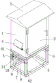
FIG. 1 is a schematic structural view of the present invention;
fig. 2 is an enlarged schematic view of the a position of the present invention.
In the figure: 1 cabinet body, 2 cabinet doors, 3 filter screens, 4 rain eaves, 5 rain-proof caps, 6 mounting bracket units, 61 upper support frame, 62 lower support frame, 63 support cover, 64 location strip, 65 recess, 66 baffles, 67 spring, 7 connecting strips, 8 pivots, 9 locating plates, 10 lugs, 11 handles, 12 round holes, 13 nuts.
Detailed Description
The technical solutions in the embodiments of the present invention will be described clearly and completely with reference to the drawings in the embodiments of the present invention, and it is obvious that the described embodiments are only some embodiments of the present invention, not all embodiments. Based on the embodiments in the present invention, all other embodiments obtained by a person skilled in the art without creative efforts all belong to the protection scope of the present invention.
Referring to fig. 1-2, the present embodiment provides a technical solution: a power distribution cabinet with an adjustable mounting rack comprises a cabinet body 1 and a mounting rack unit 6;
the cabinet body 1: the front end of the electric appliance cabinet is hinged with a cabinet door 2 through a hinge, the cabinet body 1 provides an installation place for electric appliance elements, the cabinet door 2 facilitates the installation of the electric appliance elements, filter screens 3 are respectively arranged at the radiating holes on the left side surface and the right side surface of the cabinet body 1, dust is placed in the filter screens 3 to enter the cabinet body 1, a rain-proof cap 5 is arranged on the upper surface of the cabinet body 1, the rain-proof cap 5 improves the waterproof effect of the cabinet body 1, and rain-proof eaves 4 are respectively arranged at the radiating holes on the left side surface and the right side surface of the cabinet body 1 to prevent rainwater from passing through the filter screens 3;
the mounting bracket unit 6: the cabinet comprises an upper supporting frame 61 and a lower supporting frame 62, wherein the upper supporting frame 61 is arranged on the lower surface of a cabinet body 1, the lower end of the upper supporting frame 61 is connected with the lower supporting frame 62 in a sliding manner, the lower supporting frame 62 is connected with a fixed foundation by using bolts during installation, when the height of the cabinet body 1 needs to be adjusted, the cabinet body 1 can be pulled upwards or pressed downwards, and then the cabinet body 1 drives the upper supporting frame 61 to vertically slide along the lower supporting frame 62, the mounting frame unit 6 further comprises a supporting sleeve 63, positioning strips 64 and grooves 65, the supporting sleeve 63 is respectively and uniformly arranged at the upper end of the lower supporting frame 62, the positioning strips 64 are respectively and uniformly connected inside the supporting sleeve 63 in a sliding manner, the grooves 65 are respectively and uniformly arranged at the upper end of the upper supporting frame 61, one end of each positioning strip 64, which is far away from the longitudinal center of the lower supporting frame 62, is movably inserted into the adjacent grooves 65, the mounting frame unit 6 further comprises a baffle plate 66 and a spring 67, the baffle plates 66 are respectively arranged at one end of the support sleeve 63 close to the longitudinal center of the lower support frame 62, springs 67 are respectively arranged on opposite back-to-back surfaces of two corresponding baffle plates 66, the springs 67 are respectively positioned inside the positioning strips 64, an avoiding groove is formed at one end of each positioning strip 64 close to the baffle plate 66, the avoiding groove is matched with the baffle plate 66 to ensure the normal sliding of the positioning strips 64, meanwhile, the heads of the grooves 65 and the positioning strips 64 are arc-shaped, the grooves 65 can pull out the positioning strips 64 in the vertical moving process of the upper support frame 61, the positioning strips 64 slide relative to the support sleeve 63 and extrude the springs 67, when the grooves 65 correspond to the positions of the positioning strips 64, the springs 67 drive the positioning strips 64 to slide along the support sleeve 63 in the direction far away from the baffle plates 66 under the support of the baffle plates 66, and the positioning strips 64 are continuously inserted in the grooves 65, and then can carry out interim location to upper bracket 61, the left and right sides of the upper end of lower carriage 62 all is equipped with connecting strip 7, it is connected with pivot 8 to rotate between two connecting strips 7, connecting strip 7 provides the mounted position for pivot 8, the outside of connecting strip 7 extends respectively at the both ends of pivot 8, the both ends of pivot 8 all are equipped with locating plate 9, locating strip 64 all sets up with adjacent locating plate 9 cooperation, the extrados of pivot 8 is equipped with handle 11, the left surface of left connecting strip 7 is equipped with lug 10, lug 10 sets up with left locating plate 9 cooperation, lug 10 restriction left locating plate 9 rotatory angle, still include round hole 12 and nut 13, round hole 12 sets up the left surface at left locating plate 9, nut 13 sets up in the left surface of left connecting strip 7, nut 13 sets up with round hole 12 cooperation, after the altitude mixture control of the cabinet body 1 finishes, can move handle 11, handle 11 drives locating plate 9 through pivot 8 and rotates, round hole 12 corresponds with the position of nut 13 after the synchronous movement of locating plate 9 along with locating plate 9, and then use stud 12 and 13 to pass threaded connection, then restriction the rotatory end of locating plate 9 should restrict the clockwise the location of nut 64, the locating strip of cabinet body 64 and carry out the location because of this location.
The utility model provides a pair of switch board of adjustable mounting bracket in area's theory of operation as follows: when the height of the cabinet body 1 needs to be adjusted, the cabinet body 1 can be pulled upwards or pressed downwards, the cabinet body 1 drives the upper support frame 61 to slide vertically along the lower support frame 62, the heads of the groove 65 and the positioning bar 64 are both arc-shaped, the groove 65 can pull out the positioning bar 64 in the vertical movement process of the upper support frame 61, the positioning bar 64 slides relative to the support sleeve 63 and extrudes the spring 67, when the groove 65 corresponds to the position of the positioning bar 64, the spring 67 drives the positioning bar 64 to slide along the support sleeve 63 in the direction away from the baffle 66 under the support of the baffle 66, the positioning bar 64 and the groove 65 are continuously inserted into the groove 65, the upper support frame 61 can be temporarily positioned, after the height of the cabinet body 1 is adjusted, the handle 11 can be pulled, the handle 11 drives the handle 9 to rotate clockwise through the rotating shaft 8, meanwhile, after the circular hole 12 synchronously moves along with the positioning plate 9, the position of the positioning bar 13 corresponds to the position of the circular hole 13, then the stud penetrates through the screw thread of the screw cap 13, and then the positioning plate 9 is linked, the positioning plate 64 can be limited to move towards the positioning plate 64, and the positioning plate 64 can be moved towards the positioning plate.
The above-mentioned only be the embodiment of the present invention, not consequently the restriction of the patent scope of the present invention, all utilize the equivalent structure or equivalent flow transform made of the content of the specification and the attached drawings, or directly or indirectly use in other relevant technical fields, all including in the same way the patent protection scope of the present invention.
Claims (7)
1. The utility model provides a switch board of adjustable mounting bracket in area which characterized in that: comprises a cabinet body (1) and a mounting rack unit (6);
cabinet (1): the front end of the cabinet body is hinged with a cabinet door (2) through a hinge, and filter screens (3) are arranged at the radiating holes on the left side surface and the right side surface of the cabinet body (1);
a mounting frame unit (6): the cabinet comprises an upper supporting frame (61) and a lower supporting frame (62), wherein the upper supporting frame (61) is arranged on the lower surface of the cabinet body (1), and the lower end of the upper supporting frame (61) is slidably connected with the lower supporting frame (62).
2. The utility model discloses a switch board of adjustable mounting bracket in area of claim 1 which characterized in that: the mounting bracket unit (6) further comprises a support sleeve (63), a positioning strip (64) and a groove (65), the support sleeve (63) is uniformly arranged at the upper end of the lower support frame (62) respectively, the positioning strip (64) is connected to the inside of the support sleeve (63) in a sliding mode, the groove (65) is uniformly arranged at the upper end of the upper support frame (61) respectively, and one end, far away from the longitudinal center of the lower support frame (62), of the positioning strip (64) is movably connected with the adjacent groove (65) in a plugging mode respectively.
3. The utility model discloses a switch board of adjustable mounting bracket in area of claim 2, its characterized in that: mounting bracket unit (6) still include baffle (66) and spring (67), baffle (66) set up respectively in supporting cover (63) and are close to the one end at the vertical center of under bracing frame (62), and the relative back of the body of two vertical corresponding baffles (66) all is equipped with spring (67), and spring (67) are located the inside of location strip (64) respectively, and the one end that location strip (64) are close to baffle (66) has been seted up and has been dodged the groove, dodges groove and baffle (66) cooperation setting.
4. The utility model discloses a switch board of adjustable mounting bracket in area of claim 2, characterized in that: the left and right sides of lower carriage (62) upper end all is equipped with connecting strip (7), rotates between two connecting strips (7) and is connected with pivot (8), and the outside of connecting strip (7) is extended respectively at the both ends of pivot (8), and the both ends of pivot (8) all are equipped with locating plate (9), and locating strip (64) all sets up with adjacent locating plate (9) cooperation.
5. The utility model discloses a switch board of adjustable mounting bracket in area of claim 4, its characterized in that: the outer arc surface of the rotating shaft (8) is provided with a handle (11), the left side surface of the left connecting strip (7) is provided with a convex block (10), and the convex block (10) is matched with the left positioning plate (9).
6. The utility model discloses a switch board of adjustable mounting bracket in area of claim 4, its characterized in that: still include round hole (12) and nut (13), the left surface of left locating plate (9) is seted up in round hole (12), and nut (13) set up in the left surface of left connecting strip (7), and nut (13) and round hole (12) cooperation set up.
7. The utility model discloses a switch board of adjustable mounting bracket in area of claim 1 which characterized in that: the upper surface of the cabinet body (1) is provided with a rain-proof cap (5), and the radiating holes on the left side surface and the right side surface of the cabinet body (1) are provided with rain-proof eaves (4).
Priority Applications (1)
| Application Number | Priority Date | Filing Date | Title |
|---|---|---|---|
| CN202222396734.9U CN218602991U (en) | 2022-09-09 | 2022-09-09 | Power distribution cabinet with adjustable mounting rack |
Applications Claiming Priority (1)
| Application Number | Priority Date | Filing Date | Title |
|---|---|---|---|
| CN202222396734.9U CN218602991U (en) | 2022-09-09 | 2022-09-09 | Power distribution cabinet with adjustable mounting rack |
Publications (1)
| Publication Number | Publication Date |
|---|---|
| CN218602991U true CN218602991U (en) | 2023-03-10 |
Family
ID=85398048
Family Applications (1)
| Application Number | Title | Priority Date | Filing Date |
|---|---|---|---|
| CN202222396734.9U Active CN218602991U (en) | 2022-09-09 | 2022-09-09 | Power distribution cabinet with adjustable mounting rack |
Country Status (1)
| Country | Link |
|---|---|
| CN (1) | CN218602991U (en) |
-
2022
- 2022-09-09 CN CN202222396734.9U patent/CN218602991U/en active Active
Similar Documents
| Publication | Publication Date | Title |
|---|---|---|
| CN111641370B (en) | Solar photovoltaic board convenient to remove | |
| CN218602991U (en) | Power distribution cabinet with adjustable mounting rack | |
| CN216345285U (en) | Remote monitoring network information security camera | |
| CN214337269U (en) | Power distribution cabinet elevation support and power distribution cabinet assembly comprising same | |
| CN214255355U (en) | Disconnect-type high tension switchgear | |
| CN115173261A (en) | Electrical cabinet with slidable turnover type mounting plate | |
| CN113904219A (en) | Connecting mechanism for mounting components of cabinet body structure of electric power cabinet | |
| CN218000910U (en) | Intelligent building control center monitor screen mounting bracket | |
| CN115602417B (en) | Auxiliary device and method for mounting distribution transformer | |
| CN217428049U (en) | Adjustable photovoltaic board mounting bracket that removes | |
| CN214065522U (en) | Chemical reagent drying device | |
| CN210577078U (en) | JP cabinet box body mounting structure | |
| CN218734041U (en) | Solar photovoltaic support convenient to installation | |
| CN219204391U (en) | Photovoltaic board fixing device convenient to joint | |
| CN213692709U (en) | Intelligent power distribution cabinet convenient to maintain | |
| CN220401350U (en) | Welding-free cable bridge mounting member for steel structure bridge | |
| CN217969384U (en) | Luggage rack mounting bracket convenient to disassemble and assemble | |
| CN220086704U (en) | Subway regulator cubicle that fastness is strong | |
| CN219359299U (en) | Bearing device for copper door assembly | |
| CN213783182U (en) | Photovoltaic support that stability is good | |
| CN211266090U (en) | Distributed power supply safety power distribution cabinet | |
| CN219394764U (en) | Angle-adjustable solar photovoltaic power generation panel bracket | |
| CN220822976U (en) | Photovoltaic board position control subassembly | |
| CN216556270U (en) | Monitoring support with adjusting function | |
| CN220492909U (en) | Adjustable photovoltaic support |
Legal Events
| Date | Code | Title | Description |
|---|---|---|---|
| GR01 | Patent grant | ||
| GR01 | Patent grant |