CN218593589U - Novel high-precision through hole cutting tool - Google Patents
Novel high-precision through hole cutting tool Download PDFInfo
- Publication number
- CN218593589U CN218593589U CN202221928164.7U CN202221928164U CN218593589U CN 218593589 U CN218593589 U CN 218593589U CN 202221928164 U CN202221928164 U CN 202221928164U CN 218593589 U CN218593589 U CN 218593589U
- Authority
- CN
- China
- Prior art keywords
- hole
- plate
- cutter
- novel high
- cutting tool
- Prior art date
- Legal status (The legal status is an assumption and is not a legal conclusion. Google has not performed a legal analysis and makes no representation as to the accuracy of the status listed.)
- Active
Links
Images

Abstract
The utility model provides a novel high accuracy cuts through-hole frock, relates to cutting die technical field, include by lower bolster and the lower mould fixed plate that sets up side by side from the top down, be equipped with the cutter and the through-hole needle of vertical setting on the lower mould fixed plate side by side, the top of lower bolster has the cope match-plate pattern along vertical lift, and when the lower bolster offseted with the cope match-plate pattern, pushes down the lower bolster, and the upper end of cutter and through-hole needle stretches out in the upper surface of lower bolster. The utility model provides an injection moulding back runner can not with product autosegregation in the conventional art, the easy plug hole of aperture, because the aperture is less, lead to pruning inefficiency, the lower problem of yield.
Description
Technical Field
The utility model relates to a cutting die technical field, concretely relates to novel high-accuracy through-hole frock that cuts.
Background
The plastic products are widely applied to every field in modern life, such as household appliances, instruments and meters, electric wires and cables, building equipment, communication electronics, automobile industry, aerospace, daily hardware and the like, and can be seen. Most plastic products are all injection-molded by injection mold, and its injection molding process is: the sol enters a mold cavity through a runner and a pouring gate for molding, the residual sol in the pouring gate and a plastic product are integrally molded to form a stub bar, after molding is completed, the mold is opened, the plastic product after injection molding is ejected by an ejector pin, and during production of the plastic product, part of redundant parts can be generated, so that cutting needs to be performed on a specific jig.
The technical scheme includes that the device comprises a main body, wherein a buffer assembly is arranged at the bottom of the main body, a placing bin is arranged in the middle of the interior of the main body, a plurality of groups of rotating rods are uniformly arranged at the bottom of the placing bin, rolling shafts are sleeved on the outer sides of the rotating rods, limiting grooves are formed in two sides of the bottom of the placing bin, one end of each limiting groove is communicated with the interior of the main body, and a servo motor is arranged at the bottom of the main body; the utility model discloses a mutually supporting of servo motor, horizontal pole, hinge bar C, spacing groove, mounting panel, outer tube, extrusion piece, mounting groove B, mounting groove A and spring E, through adopting the bottom to rotate the hinge bar C that drives both sides and contract toward the lining to drive the mounting panel, reach the centre gripping location, it is more accurate when making it cut, adopt the fixed position mode of multiunit centre gripping moreover, the both sides of the plastic products of laminating more improve its location effect.
The device gradually exposes the defects of the technology along with production and use, and mainly shows the following aspects:
the existing part of products are subjected to edge glue feeding, at least 100 through holes with the diameter of less than 0.15mm are formed in the surfaces of the products, a pouring gate cannot be automatically separated from the products after injection molding, the hole blocking phenomenon can also occur in small holes, the pouring gate cannot be trimmed by the existing device due to the small hole diameter, the pouring gate needs to be trimmed manually, manual trimming efficiency and yield are low, potential safety hazards exist in the use process of the blade, and once the through holes are blocked, the products are directly scrapped.
In view of the above, the prior art is obviously inconvenient and disadvantageous in practical use, and needs to be improved.
SUMMERY OF THE UTILITY MODEL
To the defect among the prior art, the utility model provides a novel high accuracy cuts through-hole frock for solve injection moulding back runner in the prior art can not with product autosegregation, the stifled hole phenomenon also can appear in the aperture, because the aperture is less, lead to pruning inefficiency, the lower problem of yield.
In order to achieve the above object, the utility model provides a following technical scheme:
the utility model provides a novel high accuracy cuts through-hole frock, includes lower bolster and lower mould fixed plate by last lower bolster and the lower mould fixed plate that sets up side by side down, be equipped with cutter and the through-hole needle of vertical setting on the lower mould fixed plate side by side, there is the cope match-plate pattern in the top of lower bolster along vertical lift, the lower bolster with when the cope match-plate pattern offsets, will the lower bolster pushes down, the upper end of cutter and through-hole needle stretch out in the upper surface of lower bolster.
As an optimized scheme, a spring is vertically arranged between the lower die plate and the lower die fixing plate, the upper end of the spring is abutted against the lower die plate, and the lower end of the spring is abutted against the lower die fixing plate.
As an optimized scheme, a mounting plate is further arranged between the lower die plate and the lower die fixing plate, and cutter fixing holes for fixing the cutters are formed in the mounting plate.
As an optimized scheme, a through hole needle fixing hole for fixing the through hole needle is further formed in the mounting plate.
As an optimized scheme, the lower end parts of the cutter and the through hole needle are respectively abutted against the upper surface of the lower die fixing plate.
As an optimized scheme, an upper die fixing plate is connected above the upper die plate through bolts.
As an optimized scheme, the upper end part of the upper die fixing plate is connected with a machine handle.
As an optimized scheme, guide pillars are fixedly connected to the upper surface of the lower die fixing plate in a vertical and parallel mode, and penetrate through the mounting plate, the lower die plate, the upper die plate and the upper die fixing plate.
As an optimized scheme, the upper template is further provided with an edge lock.
As an optimized scheme, the lower template is provided with a cutter avoiding hole and a through hole needle avoiding hole which are used for avoiding the cutter and the through hole needle.
As an optimized scheme, an air faucet is further arranged on the side wall of the lower template, the lower template is provided with an inner cavity communicated with the through-hole needle avoiding hole, and the air faucet is communicated with the inner cavity.
As an optimized scheme, the lower template is further provided with positioning pins corresponding to the product.
As an optimized scheme, the through hole needles are arranged in parallel, and the number of the cutting knives is two, and the two cutting knives are respectively arranged on two sides of the through hole needles.
Compared with the prior art, the utility model has the advantages that:
the safety in the production process is ensured; the production efficiency and the product percent of pass are improved by 5 percent;
when in cutting, the product is placed in a lower template and is positioned by a positioning needle;
the punching machine is connected with the machine handle and is pressed downwards, the upper die fixing plate and the upper die plate move downwards along with the lower die plate for a certain distance, the upper die plate and the lower die plate are positioned through the guide pillar and the side lock, the upper die plate and the lower die plate are closed to tightly press a product (the product is prevented from shaking when a sprue is cut), and at the moment, due to the action of the spring below the lower die plate, the cutter and the through hole needle are not in contact with the product;
the closed upper die fixing plate, the closed upper die plate and the closed lower die plate continue to move downwards under the action of the punching machine to offset the elasticity of the spring, so that the lower die plate and the mounting plate are closed; in the closing process, the cutter and the through hole needle relatively move upwards to start the action of cutting off the sprue and the through hole, when the sprue is completely closed, the sprue is cut off to realize complete separation from a product, and the blocked hole can be opened; and finally, blowing by using an air nozzle, and taking out the product from the tool.
Drawings
In order to more clearly illustrate the embodiments of the present invention or the technical solutions in the prior art, the drawings used in the embodiments or the technical solutions in the prior art will be briefly described below. Throughout the drawings, like elements or portions are generally identified by like reference numerals. In the drawings, elements or portions are not necessarily drawn to scale.
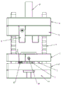
Fig. 1 is a schematic structural view of the present invention;
fig. 2 is a schematic structural view of the cross section of the present invention.
In the figure: 1-a lower template; 2-cutting the knife; 3-a through-hole needle; 4, mounting a template; 5-side locking; 6-a spring; 7-a guide post; 8-upper die fixing plate; 9-a machine handle; 10-mounting a plate; 11-lower die fixing plate; 12-a bolt; 13-product; 14-a positioning pin; 15-air nozzle.
Detailed Description
Embodiments of the present invention will be described in detail with reference to the accompanying drawings. The following examples are only for illustrating the technical solutions of the present invention more clearly, and therefore are only examples, and the protection scope of the present invention is not limited thereby.
As shown in fig. 1 and 2, novel high-precision through-hole cutting tool comprises a lower template 1 and a lower template fixing plate 11 which are arranged from top to bottom in parallel, wherein a cutter 2 and a through-hole needle 3 which are vertically arranged are arranged on the lower template fixing plate 11 in parallel, an upper template 4 is arranged above the lower template 1 along vertical lifting, when the lower template 1 is offset with the upper template 4, the lower template 1 is pressed downwards, and the upper end parts of the cutter 2 and the through-hole needle 3 stretch out of the upper surface of the lower template 1.
And a spring 6 is vertically arranged between the lower die plate 1 and the lower die fixing plate, the upper end part of the spring 6 is propped against the lower die plate 1, and the lower end part of the spring 6 is propped against the lower die fixing plate 11.
A mounting plate 10 is further arranged between the lower die plate 1 and the lower die fixing plate 11, and cutter fixing holes for fixing the cutters 2 are formed in the mounting plate 10.
The mounting plate 10 is further provided with a through-hole needle fixing hole for fixing the through-hole needle 3.
The lower end parts of the cutter 2 and the through-hole needle 3 are respectively abutted against the upper surface of the lower die fixing plate 11.
An upper die fixing plate 8 is connected above the upper die plate 4 through bolts 12.
The upper end part of the upper die fixing plate 8 is connected with a handle 9.
The upper surface of the lower die fixing plate 11 is vertically and fixedly connected with guide posts 7 in parallel, and the guide posts 7 penetrate through the mounting plate 10, the lower die plate 1, the upper die plate 4 and the upper die fixing plate 8.
The upper template 4 is also provided with an edge lock 5.
The lower template 1 is provided with a cutter avoiding hole and a through hole needle avoiding hole which avoid the cutter 2 and the through hole needle 3.
The side wall of the lower template 1 is also provided with an air nozzle 15, the lower template 1 is provided with an inner cavity communicated with the through hole needle avoiding hole, and the air nozzle 15 is communicated with the inner cavity.
The lower template 1 is also provided with positioning pins 14 corresponding to the products 13.
The through hole needles 3 are arranged in parallel, and the number of the cutters 2 is two and the cutters are respectively arranged on two sides of the through hole needles 3.
The working principle of the device is as follows:
when cutting, the product 13 is placed in the lower template 1, and the product 13 is positioned through the positioning needle 14;
the punching machine is connected with a machine handle 9 and is pressed downwards, an upper die fixing plate 8 and an upper die plate 4 move downwards along with the machine handle, the upper die fixing plate and the lower die plate are positioned with the lower die plate 1 through a guide pillar 7 and an edge lock 5, the upper die plate 4 and the lower die plate 1 are closed to press a product 13 (the product 13 is prevented from shaking when a sprue is cut), and at the moment, due to the action of a spring 6 below the lower die plate 1, a cutter 2 and a through hole needle 3 are not in contact with the product 13;
the closed upper die fixing plate 8, the closed upper die plate 4 and the closed lower die plate 1 continue to move downwards under the action of the punching machine to offset the elasticity of the spring 6, so that the lower die plate 1 and the mounting plate are closed; in the closing process, the cutter 2 and the through hole needle 3 relatively move upwards to start the action of cutting off the pouring gate and the through hole, when the pouring gate is completely closed, the pouring gate is cut off to be completely separated from the product 13, and the blocked hole can be opened; finally, the air nozzle 15 blows air, and the product 13 is taken out of the tool.
Finally, it should be noted that: the above embodiments are only used to illustrate the technical solution of the present invention, and not to limit the same; although the present invention has been described in detail with reference to the foregoing embodiments, it should be understood by those skilled in the art that: the technical solutions described in the foregoing embodiments may still be modified, or some or all of the technical features may be equivalently replaced; such modifications and substitutions do not substantially depart from the scope of the embodiments of the present invention, and are intended to be covered by the claims and the specification.
Claims (9)
1. The utility model provides a novel high accuracy cuts through-hole frock which characterized in that: the die comprises a lower template (1) and a lower template fixing plate (11) which are arranged from top to bottom in parallel, wherein the lower template fixing plate (11) is provided with a cutter (2) and a through hole needle (3) which are arranged vertically in parallel, an upper template (4) is arranged above the lower template (1) in a vertical lifting mode, the lower template (1) is pressed downwards when the lower template (1) is abutted against the upper template (4), the upper ends of the cutter (2) and the through hole needle (3) extend out of the upper surface of the lower template (1),
a spring (6) is vertically arranged between the lower die plate (1) and the lower die fixing plate (11), the upper end of the spring (6) is abutted against the lower die plate (1), and the lower end of the spring (6) is abutted against the lower die fixing plate (11).
2. The novel high-precision through hole cutting tool according to claim 1, is characterized in that: the cutting tool is characterized in that a mounting plate (10) is further arranged between the lower die plate (1) and the lower die fixing plate (11), and a cutter fixing hole for fixing the cutter (2) is formed in the mounting plate (10).
3. The novel high-precision through hole cutting tool according to claim 2, is characterized in that: and the mounting plate (10) is also provided with a through hole needle fixing hole for fixing the through hole needle (3).
4. The novel high-precision through hole cutting tool according to claim 3, is characterized in that: the lower end parts of the cutter (2) and the through hole needle (3) are respectively abutted against the upper surface of the lower die fixing plate (11).
5. The novel high-precision through hole cutting tool according to claim 4, characterized in that: and an upper die fixing plate (8) is connected above the upper die plate (4) through a bolt (12).
6. The novel high-precision through hole cutting tool according to claim 5, is characterized in that: the upper surface of the lower die fixing plate (11) is vertically and parallelly fixedly connected with guide pillars (7), and the guide pillars (7) penetrate through the mounting plate (10), the lower die plate (1), the upper die plate (4) and the upper die fixing plate (8).
7. The novel high-precision through hole cutting tool according to claim 1, is characterized in that: the lower template (1) is provided with a cutter avoiding hole and a through hole needle avoiding hole which are used for avoiding the cutter (2) and the through hole needle (3).
8. The novel high-precision through hole cutting tool according to claim 7, is characterized in that: still be equipped with air cock (15) on the lateral wall of lower bolster (1), lower bolster (1) is equipped with the intercommunication the inner chamber in through-hole needle dodge hole, air cock (15) with the inner chamber is linked together.
9. The novel high-precision through hole cutting tool according to claim 1, is characterized in that: the lower template (1) is also provided with positioning needles (14) corresponding to the products (13).
Priority Applications (1)
| Application Number | Priority Date | Filing Date | Title |
|---|---|---|---|
| CN202221928164.7U CN218593589U (en) | 2022-07-26 | 2022-07-26 | Novel high-precision through hole cutting tool |
Applications Claiming Priority (1)
| Application Number | Priority Date | Filing Date | Title |
|---|---|---|---|
| CN202221928164.7U CN218593589U (en) | 2022-07-26 | 2022-07-26 | Novel high-precision through hole cutting tool |
Publications (1)
| Publication Number | Publication Date |
|---|---|
| CN218593589U true CN218593589U (en) | 2023-03-10 |
Family
ID=85395987
Family Applications (1)
| Application Number | Title | Priority Date | Filing Date |
|---|---|---|---|
| CN202221928164.7U Active CN218593589U (en) | 2022-07-26 | 2022-07-26 | Novel high-precision through hole cutting tool |
Country Status (1)
| Country | Link |
|---|---|
| CN (1) | CN218593589U (en) |
-
2022
- 2022-07-26 CN CN202221928164.7U patent/CN218593589U/en active Active
Similar Documents
| Publication | Publication Date | Title |
|---|---|---|
| CN110465591B (en) | Auto-parts mould convenient to use | |
| CN218593589U (en) | Novel high-precision through hole cutting tool | |
| CN211518290U (en) | Cutting and bending structure in injection mold and injection molding device | |
| CN210336727U (en) | Injection mold for packaging automobile transformer | |
| CN202846832U (en) | Injection molding pouring gate cutting device | |
| CN217803097U (en) | Injection molding pouring gate of car lamp dimming support | |
| CN213891040U (en) | Injection mold of curved surface injection molding | |
| CN209552363U (en) | A kind of mechanism of novel excision cast gate | |
| CN212123961U (en) | Vertical injection molding machine | |
| CN211730047U (en) | Fastening mechanism for injection mold | |
| CN206344443U (en) | A kind of mould of blow moulded automobile connecting pipe | |
| CN215512114U (en) | Automatic cutting device for pressure-proof water outlet of cutter in mold | |
| CN213564049U (en) | Injection mold with automatic trimming function | |
| CN217648862U (en) | Mold capable of effectively shortening main runner | |
| CN218366228U (en) | Guide mechanism for plastic mold | |
| CN217196722U (en) | Injection mold pushes up to one side | |
| CN211807517U (en) | Door guide shoe injection mold | |
| CN215849439U (en) | Simple die inner cutting mechanism | |
| CN210552829U (en) | A punching press tool for medical accessory upper cover | |
| CN218252831U (en) | Tool die-casting device | |
| CN209832497U (en) | Mould with sprue excess material cutting function | |
| CN212072817U (en) | Injection mold takes off material mechanism | |
| CN214820378U (en) | Thermosetting plastic mould | |
| CN209903810U (en) | Cut off side runner structure and injection mold in mould | |
| CN215544063U (en) | Vehicle-mounted connector metal terminal manufacturing die |
Legal Events
| Date | Code | Title | Description |
|---|---|---|---|
| GR01 | Patent grant | ||
| GR01 | Patent grant |