CN218582281U - Pressure balance valve core and valve cage sealing structure without sealing ring - Google Patents
Pressure balance valve core and valve cage sealing structure without sealing ring Download PDFInfo
- Publication number
- CN218582281U CN218582281U CN202222593667.XU CN202222593667U CN218582281U CN 218582281 U CN218582281 U CN 218582281U CN 202222593667 U CN202222593667 U CN 202222593667U CN 218582281 U CN218582281 U CN 218582281U
- Authority
- CN
- China
- Prior art keywords
- step surface
- valve
- valve core
- seal
- sealing
- Prior art date
- Legal status (The legal status is an assumption and is not a legal conclusion. Google has not performed a legal analysis and makes no representation as to the accuracy of the status listed.)
- Active
Links
Images


Landscapes
- Sliding Valves (AREA)
Abstract
The utility model discloses a sealing structure of a pressure balance valve core and a valve cage without a sealing ring, which comprises a valve core, a valve cage and a valve rod, wherein the lower end of the valve rod is fixedly connected with the valve core, a valve core hole is arranged in the valve cage, and a first upper sealing step surface and a first lower sealing step surface are arranged in the valve core hole; the valve core is internally provided with at least one pressure balance hole which vertically penetrates through the valve core, and the periphery of the valve core is provided with a second upper sealing step surface and a second lower sealing step surface, wherein when the valve core is at a closed position, the second upper sealing step surface is in hard sealing fit with the first upper sealing step surface, and the second lower sealing step surface is in hard sealing fit with the first lower sealing step surface. The utility model discloses cancelled rubber O type sealing washer and metal C type circle among the current pressure balance formula stop valve, reduced sealing element, improved the sealing reliability and prolonged the life of valve.
Description
Technical Field
The utility model relates to the technical field of valves, especially, relate to stop valve technical field, in particular to mainly used enters pressure balance case and valve cage seal structure of the no sealing ring who exceeds high-pressure stop valve lowly.
Background
Referring to fig. 2, a valve core 1 of the conventional stop valve is a solid valve core and is connected with a valve rod 2, the valve core 1 is pressed against a valve seat (see fig. 1) by the downward thrust of the valve rod 2 to realize the sealing of the stop valve, the structure of the valve core 1 increases with the increase of the sealing diameter and the valve pressure, the acting force F0 of a medium on the valve rod 2 is larger, and the valve rod 2 must be thickened, otherwise, the valve core will be bent to fail.
With the progress of the process technologies of petroleum, petrochemical industry, coal chemical industry and the like, the use temperature and the use pressure of the valve are greatly improved, the production scale is enlarged, the caliber of the valve is greatly increased, and a valve core of a stop valve with a conventional structure can not be bent to fail only by a thick valve rod.
Referring to fig. 3 and 4, although the valve cartridge 1a also has a pressure balance design to reduce the force applied to the valve stem 2, the temperature and life of the valve are limited due to the addition of a sealing ring. If the sealing ring adopts the rubber 0 type sealing ring 3 (see fig. 3), the highest temperature of the sealing ring generally can not exceed 200 ℃, the highest using pressure does not exceed 25MPa, and two sealing leakage points M3 and M4 exist between the rubber 0 type sealing ring 3 and the valve core 1a and the valve cage 4a, so that the probability of sealing failure is increased and the reliability is reduced due to the increase of the number of the sealing leakage points M3 and M4.
If the sealing ring adopts the metal C-shaped ring 5, the metal C-shaped ring 5 also has two sealing leakage points M1 and M2, one is the sealing leakage point M1 between the inner side of the metal C-shaped ring 5 and the valve core 1a, and the other is the sealing leakage point M2 between the outer side of the metal C-shaped ring 5 and the valve cage 4, and the sealing leakage points M1 and M2 are increased, so that the probability of sealing failure is improved, and the reliability is reduced. In addition, if the sealing ring adopts the metal C-shaped ring 5, the metal C-shaped ring 5a generates friction and abrasion with the valve cage 4a in the process of moving up and down along with the valve core 1a, so that sealing failure is caused.
SUMMERY OF THE UTILITY MODEL
The utility model aims to solve the technical problem that the valve core to current pressure balance formula stop valve and the problem that the seal structure between the valve cage exists provide one kind can bear the pressure balance case and the valve cage seal structure of the no sealing ring of the sealed grade that can bear higher pressure differential and higher service temperature and improve the stop valve.
In order to realize the purpose of the utility model, the sealing structure of the pressure balance valve core and the valve cage without the sealing ring comprises the valve core, the valve cage and the valve rod, wherein the lower end of the valve rod is fixedly connected with the valve core, a valve cage hole is arranged in the valve cage, and a first upper sealing step surface and a first lower sealing step surface are arranged in the valve cage hole; the valve core is internally provided with at least one pressure balance hole which vertically penetrates through the valve core, and the valve core is characterized in that a second upper sealing step surface and a second lower sealing step surface are arranged on the periphery of the valve core, wherein when the valve core is in a closed position, the second upper sealing step surface is in hard sealing fit with the first upper sealing step surface, and the second lower sealing step surface is in hard sealing fit with the first lower sealing step surface.
In a preferred embodiment of the present invention, an upper radial groove is provided below the second upper sealing step surface, and the second upper sealing step surface is pressed against the first upper sealing step surface under the pressure action of the medium.
The utility model discloses a preferred embodiment set up sunken step face in the top of second upper seal step face, the pressure of medium is in when sunken step face is in, make the case be located sunken step face with the part between the radial recess has certain elasticity, will second upper seal step face sticiss on the first upper seal step face.
In a preferred embodiment of the present invention, a pressure balance cavity is disposed at the middle lower portion of the valve core, so that the cavity wall of the pressure balance cavity located at the upper portion of the second lower sealing step surface has a certain elasticity, and the second lower sealing step surface is tightly pressed on the first lower sealing step surface under the action of the medium pressure in the pressure balance cavity.
In the utility model discloses a preferred embodiment the case is located be provided with the second radial recess on the periphery of second lower sealing step face upper portion, in order to further improve the elasticity that the pressure balance chamber is located the chamber wall on second lower sealing step face upper portion makes simultaneously the case is located the periphery of second lower sealing step face upper portion can not produce size interference because of the case hole of taking place elastic deformation with the valve cage.
In a preferred embodiment of the present invention, the first upper sealing step surface, the first lower sealing step surface, the second upper sealing step surface, and the second lower sealing step surface are formed by direct surfacing.
In a preferred embodiment of the present invention, the material used for the direct surfacing of the first upper sealing step surface, the first lower sealing step surface, the second upper sealing step surface, and the second lower sealing step surface is a hard alloy material with wear resistance and high temperature resistance.
In a preferred embodiment of the present invention, the first upper sealing step surface, the first lower sealing step surface, the second upper sealing step surface, and the second lower sealing step surface are conical surfaces.
Since the technical scheme as above is used, the utility model discloses cancelled rubber O type sealing washer and metal C type circle in the current pressure balance formula stop valve, formed the direct build-up welding of sealed step face, second under the first sealed step face, the second of case and valve cage on, reduced sealing element, improved the sealing reliability and prolonged the life of valve.
Compared with the prior art, the utility model, have following advantage:
1. the utility model discloses under the condition of same valve rod diameter, the valve can bear higher pressure differential.
2. The utility model discloses do not use rubber seal material, the valve can bear higher temperature.
3. The utility model discloses owing to do not adopt metal C type circle for do not have friction and wearing and tearing between case and the valve cage, the valve is opened and close in a flexible way, and operation thrust and pulling force are little, can use littleer pneumatic actuator.
4. The utility model discloses a sealed step face adopts under first last sealed step face, first sealed step face, the second sealed step face of wearing and tearing, high temperature resistant carbide material direct build-up welding to form, cancels two sealed leak points of rubber O type sealing washer and metal C type circle, has reduced the leak point of sealing element with the case, improves the sealed grade of valve.
Drawings
FIG. 1 is a schematic illustration of a cage construction.
Fig. 2 is a schematic diagram of a non-pressure-balanced valve core structure.
Fig. 3 is a schematic structural diagram of a pressure-balanced valve element using a rubber O-ring as a sealing element.
Fig. 4 is a schematic structural diagram of a pressure-balanced valve core using a metal C-ring as a sealing element.
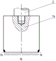
Fig. 5 is a schematic diagram of the pressure balanced valve core structure of the present invention.
Detailed Description
The invention is further described with reference to the drawings and the detailed description
Referring to fig. 1 and 5, the pressure balance valve core and cage sealing structure without a sealing ring shown in the figures includes a valve core 1b, a cage 4 and a valve rod 2, wherein the lower end of the valve rod 2 is fixedly connected with the valve core 1b, for example, the lower end of the valve rod 2 is fixedly connected with the valve core 1b in a threaded manner.
A valve core hole 4a is formed in the valve cage 4, and a first upper sealing step surface Faa and a first lower sealing step surface fdd are formed in the valve core hole 4 a; the first upper sealing step surface Faa and the first lower sealing step surface Fdd are formed by directly overlaying a wear-resistant and high-temperature-resistant hard alloy material. The first upper seal step surface Faa and the first lower seal step surface fdd are both tapered surfaces.
At least one pressure balance hole 1ba which penetrates through the valve core 1b up and down is arranged in the valve core 1b, so that the valve core 1b becomes a pressure balance valve core.
The utility model is characterized in that: the periphery of the valve core 1b is provided with a second upper sealing step surface Fa and a second lower sealing step surface Fd, and the second upper sealing step surface Fa and the second lower sealing step surface Fd are formed by direct surfacing of wear-resistant and high-temperature-resistant hard alloy materials. The second upper sealing step surface Fa and the second lower sealing step surface Fd are both conical surfaces.
When the valve core 1b is in the closed position, the second upper seal step surface Fa is in hard seal fit with the first upper seal step surface Faa, and the second lower seal step surface Fd is in hard seal fit with the first lower seal step surface Fd.
In order to press the second upper seal stepped surface Fa against the first upper seal stepped surface Faa. An upper radial groove 1bb is arranged below the second upper sealing step face Fa, a sunken step face 1bc is arranged above the second upper sealing step face Fa, and when the pressure F3 of a medium acts on the sunken step face 1bc, a part 1bd of the valve core 1b, which is positioned between the sunken step face 1bc and the upper radial groove 1bb, has certain elasticity, so that the second upper sealing step face Fa is tightly pressed on the first upper sealing step face Fa.
Further, a pressure balance chamber 1be is arranged at the middle lower part in the valve core 1b, so that a chamber wall 1bf of the pressure balance chamber 1be, which is located at the upper part of the second lower sealing step surface Fd, has certain elasticity, and the second lower sealing step surface Fd is tightly pressed on the second lower sealing step surface Fdd under the action of medium pressure F2 in the pressure balance chamber 1 be.
Furthermore, a second radial groove 1bg is formed in the outer periphery of the upper portion of the second lower sealing step surface Fd of the valve core 1b, so as to further improve the elasticity of the cavity wall 1BF of the pressure balance cavity 1be, which is located on the upper portion of the second lower sealing step surface Fd, and meanwhile, the outer periphery of the upper portion of the second lower sealing step surface Fd of the valve core 1b does not generate size interference with the valve core hole 4a of the valve cage 4 when the valve core is elastically deformed, so that the operation is facilitated.
Claims (8)
1. A pressure balance valve core and valve cage sealing structure without a sealing ring comprises a valve core, a valve cage and a valve rod, wherein the lower end of the valve rod is fixedly connected with the valve core, a valve cage hole is formed in the valve cage, and a first upper sealing step surface and a first lower sealing step surface are arranged in the valve cage hole; the valve core is internally provided with at least one pressure balance hole which vertically penetrates through the valve core, and the valve core is characterized in that a second upper sealing step surface and a second lower sealing step surface are arranged on the periphery of the valve core, wherein when the valve core is in a closed position, the second upper sealing step surface is in hard sealing fit with the first upper sealing step surface, and the second lower sealing step surface is in hard sealing fit with the first lower sealing step surface.
2. The seal ring-less pressure balanced valve core and cage seal of claim 1, wherein an upper radial groove is provided below said second upper seal step surface, pressing said second upper seal step surface against said first upper seal step surface under the pressure of the medium.
3. The seal ring-less pressure balanced valve spool and cage seal of claim 2, wherein a sunken step surface is provided above said second upper seal step surface, and the pressure of the medium acts on said sunken step surface to cause the portion of the valve spool between said sunken step surface and said upper radial recess to have a certain elasticity to press said second upper seal step surface against said first upper seal step surface.
4. The seal structure of claim 1 to 3, wherein a pressure balance chamber is provided in the middle-lower portion of the valve core, such that the chamber wall of the pressure balance chamber above the second lower seal step surface has a certain elasticity, and the second lower seal step surface is pressed against the first lower seal step surface by the medium pressure in the pressure balance chamber.
5. The seal structure of claim 4, wherein a second radial groove is formed on the outer periphery of the valve core at the upper portion of the second lower seal step surface to further improve the elasticity of the cavity wall of the pressure balance cavity at the upper portion of the second lower seal step surface, and the outer periphery of the valve core at the upper portion of the second lower seal step surface does not interfere with the valve core hole of the valve cage in size due to elastic deformation.
6. The seal structure of the pressure balance valve core and the valve cage without the seal ring according to claim 1, wherein the first upper seal step surface, the first lower seal step surface, the first upper seal step surface and the first lower seal step surface are formed by direct surfacing.
7. The seal structure for the pressure balance valve core and the valve cage without the seal ring according to claim 6, wherein the first upper seal step surface, the first lower seal step surface, the second upper seal step surface and the second lower seal step surface are directly welded by a hard alloy material with wear resistance and high temperature resistance.
8. The seal structure for a pressure balanced valve plug and cage without a seal ring of claim 1, wherein the first upper seal step surface, the first lower seal step surface, the second upper seal step surface, and the second lower seal step surface are all tapered surfaces.
Priority Applications (1)
| Application Number | Priority Date | Filing Date | Title |
|---|---|---|---|
| CN202222593667.XU CN218582281U (en) | 2022-09-29 | 2022-09-29 | Pressure balance valve core and valve cage sealing structure without sealing ring |
Applications Claiming Priority (1)
| Application Number | Priority Date | Filing Date | Title |
|---|---|---|---|
| CN202222593667.XU CN218582281U (en) | 2022-09-29 | 2022-09-29 | Pressure balance valve core and valve cage sealing structure without sealing ring |
Publications (1)
| Publication Number | Publication Date |
|---|---|
| CN218582281U true CN218582281U (en) | 2023-03-07 |
Family
ID=85367106
Family Applications (1)
| Application Number | Title | Priority Date | Filing Date |
|---|---|---|---|
| CN202222593667.XU Active CN218582281U (en) | 2022-09-29 | 2022-09-29 | Pressure balance valve core and valve cage sealing structure without sealing ring |
Country Status (1)
| Country | Link |
|---|---|
| CN (1) | CN218582281U (en) |
-
2022
- 2022-09-29 CN CN202222593667.XU patent/CN218582281U/en active Active
Similar Documents
| Publication | Publication Date | Title |
|---|---|---|
| EP2238380B1 (en) | Energized composite metal to metal seal | |
| NO860722L (en) | DOUBLE METAL SEAL FOR A FIREFIGHTING VALVE. | |
| US5284205A (en) | Metal to metal seal for well safety valve | |
| CN218582281U (en) | Pressure balance valve core and valve cage sealing structure without sealing ring | |
| WO2016155319A1 (en) | Multi-protection corrugated pipe stop valve for chlorine use | |
| US10578229B2 (en) | Flexible stem bellow assembly | |
| CN202790608U (en) | High-temperature high-pressure flat gate valve | |
| CN105065700B (en) | A kind of self-sealed gate valve structure | |
| CN117052936B (en) | Ball valve with four valve seats | |
| CN115789276A (en) | Pressure balance valve core and valve cage sealing structure without sealing ring | |
| CN108412449A (en) | A kind of all-metal is multistage and waits the mandrel type hanger of cone sealing structure | |
| CN212804434U (en) | High-temperature and high-pressure resistant balanced valve | |
| CN111946836A (en) | Two-way sealing stop valve | |
| CN108798613B (en) | Sealing structure for intelligent underground flow controller | |
| CN213899957U (en) | Valve with carbon graphite sealing ring | |
| CN205654907U (en) | High pressure resistant ball valve sealed firmly | |
| CN220081388U (en) | Float valve with reliable sealing performance | |
| CN117432864B (en) | Throttling device for valve | |
| CN108458124B (en) | A kind of sealing structure of downhole flow control valve | |
| CN212616339U (en) | Two-way sealing stop valve | |
| CN117432813B (en) | Spring type multi-stage throttling emptying valve | |
| CN219081547U (en) | Drilling tool float valve | |
| CN213064776U (en) | Novel metal floating seal ultrahigh pressure safety valve | |
| US11773983B2 (en) | High-pressure self-sealing butterfly valve | |
| CN210566471U (en) | Ultrahigh pressure check valve |
Legal Events
| Date | Code | Title | Description |
|---|---|---|---|
| GR01 | Patent grant | ||
| GR01 | Patent grant |