CN218576154U - Movable lifting workbench - Google Patents
Movable lifting workbench Download PDFInfo
- Publication number
- CN218576154U CN218576154U CN202222264046.7U CN202222264046U CN218576154U CN 218576154 U CN218576154 U CN 218576154U CN 202222264046 U CN202222264046 U CN 202222264046U CN 218576154 U CN218576154 U CN 218576154U
- Authority
- CN
- China
- Prior art keywords
- frame
- sides
- optical axis
- pole
- offset plate
- Prior art date
- Legal status (The legal status is an assumption and is not a legal conclusion. Google has not performed a legal analysis and makes no representation as to the accuracy of the status listed.)
- Active
Links
Images


Landscapes
- Forklifts And Lifting Vehicles (AREA)
Abstract
The utility model discloses a remove elevating platform, which comprises a fixing frame, fixed frame's both sides all are provided with braced frame, top frame attach is passed through on both sides braced frame's upper portion, top frame's top lid is equipped with operating panel, operating panel's both sides all are equipped with the perforation, top frame's top both sides all are provided with places the pole, both sides are placed the pole and are worn out fenestrate one end and are connected with the tee bend head, be provided with the equipment frame between the tee bend head in both sides, be provided with the light on the equipment frame, both sides are placed and are provided with the PP offset plate between the pole, one side upper portion of PP offset plate is provided with pipe sign indicating number bayonet socket, one side lower part of PP offset plate is provided with M6 screw. Place electrography, screwdriver, pincers in pipe sign indicating number bayonet socket and place, place the box spanner of different models on M6 screw, when the staff is using the workstation, can directly perceivedly take off the instrument that corresponds from pipe sign indicating number bayonet socket or M6 screw and use, improve the use convenience of workstation.
Description
Technical Field
The utility model relates to a workstation technical field specifically is removal elevating platform.
Background
In working life, the height of the workbench is often required to be adjusted due to different use scenes or users so as to meet working requirements or improve the comfort of the users; moreover, the workbench needs to be moved many times, but the workbench is heavy, so that the workbench is labor-consuming and inconvenient to move or can be moved only by a plurality of people. At present, some work tables which can move and lift are available, but the work tables support a work panel through the lower part, the space under the work panel is occupied by the work tables, and the space is not effectively utilized; and when the user needs to store, place or take articles, there is no corresponding space or cabinet or drawer, and the furniture such as cabinet or desk with drawer needs to be configured additionally, which brings great inconvenience to the user.
For example, chinese patent with publication No. CN207721426U discloses a movable lifting layer type workbench, which comprises a lifting platform, a main frame, a layer plate and casters; the main frame comprises side frames and connecting rods, the upper parts and the lower parts of the side frames which are parallel to each other are connected by the connecting rods, and the laminated plate is arranged in the main frame; the lifting platform comprises a fixed seat, a lifting arm, a working panel, a power mechanism and a control switch, the fixed seat is fixed on the upper part of the main frame, one end of the lifting arm is hinged to the fixed seat, the other end of the lifting arm is hinged to the working panel, the power mechanism for driving and locking the lifting arm is connected with the lifting arm, an angle beta is formed between the power mechanism and the lifting arm, and the control switch is connected with the power mechanism; the truckles are arranged at the bottom of the main frame.
However, the above scheme has the following disadvantages:
the main frame that only utilizes side bearer and connecting rod to build among the above-mentioned patent file, the inner space is big, convenience of customers save, get and put article, file, utilizes the space of workstation lower part simultaneously effectively, but above-mentioned patent file is accomodate in storage basket or drawer through placing the instrument, can not directly perceivedly take the instrument that corresponds the model, leads to the instrument of taking to have inconveniently more, influences the use convenience of workstation.
For this purpose, we propose moving the lifting table.
SUMMERY OF THE UTILITY MODEL
An object of the utility model is to provide a remove elevating platform to solve the problem that proposes among the above-mentioned background art.
In order to achieve the above object, the utility model provides a following technical scheme: the movable lifting workbench comprises a fixed frame, wherein supporting frames are arranged on two sides of the fixed frame, the upper parts of the supporting frames on the two sides are connected through a top frame, an operation panel is arranged on the top end cover of the top frame, through holes are formed in two sides of the operation panel, placing rods are arranged on two sides of the top end of the top frame, sliding grooves are formed in the placing rods on the two sides, and the through holes on the two sides are matched with the placing rods in shape and size;
one end of each of the two placement rods, penetrating through the through hole, is connected with a tee joint head, an equipment frame is arranged between the tee joint heads on the two sides, the equipment frame is of a square frame structure, a lighting lamp is arranged on the equipment frame, a PP (polypropylene) rubber plate is arranged between the placement rods on the two sides, a pipe code bayonet is arranged on the upper portion of one surface of the PP rubber plate, and an M screw is arranged on the lower portion of one surface of the PP rubber plate;
eight optical axis mounting blocks are symmetrically arranged on two sides of the inner wall of the supporting frame, an optical axis is arranged between two optical axis mounting blocks in the vertical direction, optical axis sliding blocks are sleeved on the four optical axes, a moving frame is arranged between the optical axis sliding blocks in the two-side symmetry, a supporting foot block is arranged in the moving frame, a panel fixing frame is arranged at the top end of the moving frame, and the top end of the panel fixing frame is fixedly connected with the lower end face of the operation panel;
the bottom both sides of fixed frame are provided with four supporting legs, two that are located the place ahead the bottom of supporting leg is provided with first gyro wheel, is located two at rear the bottom of supporting leg is provided with the brake gyro wheel.
Compared with the prior art, the beneficial effects of the utility model are that: the utility model discloses a promote first gyro wheel and brake gyro wheel and roll, after the drive removed elevating platform to the work position, carry out rigidity through the brake gyro wheel, then place the electrography, the screwdriver, the pincers are placed and are fixed the centre gripping in pipe sign indicating number bayonet socket, place the box spanner of different models on M6 screw, when the staff is using the workstation, can directly perceivedly take off the instrument that corresponds from pipe sign indicating number bayonet socket or M6 screw and use, thereby improve the convenience of use of workstation greatly.
Drawings
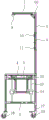
FIG. 1 is a schematic front view of the present invention;
FIG. 2 is a right side schematic view of the present invention;
fig. 3 is a left-side view of the present invention.
In the figure: 1. a fixed frame; 2. a support frame; 3. a top frame; 4. an operation panel; 5. perforating; 6. placing a rod; 60. a tee joint; 7. an equipment rack; 8. a lighting lamp; 9. PP rubber plates; 10. a pipe code bayonet; 11. an M6 screw; 12. an optical axis mounting block; 13. an optical axis; 14. an optical axis slider; 15. moving the frame; 16. a panel fixing frame; 17. supporting legs; 18. a first roller; 19. a brake roller; 20. and a supporting foot block.
Detailed Description
The technical solutions in the embodiments of the present invention will be described clearly and completely with reference to the drawings in the embodiments of the present invention, and it is obvious that the described embodiments are only some embodiments of the present invention, not all embodiments. Based on the embodiments in the present invention, all other embodiments obtained by a person skilled in the art without creative efforts all belong to the protection scope of the present invention.
Referring to fig. 1-3, the present invention provides a technical solution: the movable lifting workbench comprises a fixed frame 1, the left side and the right side of the fixed frame 1 are both connected with supporting frames 2 through connecting pieces, the connecting pieces are made of aluminum alloy materials, the upper parts of the supporting frames 2 on the left side and the right side are connected with a top frame 3 through the connecting pieces, an operating panel 4 is arranged at the top end cover of the top frame 3, the left side and the right side of the operating panel 4 are both provided with through holes 5, and the two sides of the top end of the top frame 3 are both connected with placing rods 6 through the connecting pieces;
the left and right placing rods 6 are provided with sliding grooves, the left and right through holes 5 are matched with the placing rods 6 in shape and size, one ends of the left and right placing rods 6 penetrating through the through holes 5 are connected with tee heads 60, an equipment frame 7 is connected between the tee heads 60 on the two sides through a connecting piece, and the equipment frame 7 is of a square frame structure;
the device frame 7 is fixedly connected with a lighting lamp 8 through a bolt, the input end of the lighting lamp 8 is connected with a power supply through a power line, a PP rubber plate 9 is fixedly connected between the left and right placing rods 6 through a bolt, the upper front part of the PP rubber plate 9 is fixedly connected with a pipe code bayonet 10 through a bolt, the pipe code bayonet 10 can fixedly clamp an electric pen, a screwdriver and an iron clamp, the lower front part of the PP rubber plate 9 is connected with an M6 screw 11 through a connecting piece, and the M6 screw 11 can fixedly place socket wrenches of different models;
eight optical axis installation blocks 12 are symmetrically connected to two sides of the inner wall of the supporting frame 2 through connecting pieces, an optical axis 13 is fixedly connected between the two optical axis installation blocks 12 in the vertical direction through bolts, optical axis sliders 14 are sleeved on the four optical axes 13 in a sliding mode, the optical axis sliders 14 are pushed to slide on the optical axes 13 vertically, a movable frame 15 is driven, a panel fixing frame 16 and an operation panel 4 are driven to lift vertically, the through holes 5 are driven to slide on the placing rods 6, height adjustment of the operation panel 4 is achieved, the bending labor intensity of operators is reduced, one end, penetrating out of the optical axis sliders 14, of each bolt abuts against the corresponding optical axis 13, the movable frame 15 is limited and fixed, and the optical axis sliders 14 in bilateral symmetry are connected through the inverted T-shaped movable frame 15;
the movable frame 15 is internally provided with a supporting foot block 20, the movable frame 15 and the panel fixing frame 16 are in a triangular supporting relation, the supporting stability of the panel fixing frame 16 is enhanced, the top end of the movable frame 15 is connected with the panel fixing frame 16 through a connecting piece, and the top end of the panel fixing frame 16 is fixedly connected with the lower end face of the operation panel 4 through bolts;
the bottom left and right sides of fixed frame 1 is connected with four supporting legs 17 through the connecting piece, and the bottom of two supporting legs 17 that are located the place ahead is connected with first gyro wheel 18 through the connecting piece, and the bottom of two supporting legs 17 that are located the rear is connected with brake roller 19 through the connecting piece.
The working principle of the embodiment is as follows: roll through promoting first gyro wheel 18 and brake gyro wheel 19, after the drive removed the elevating platform to the operating position, carry out the rigidity through brake gyro wheel 19, then place the electrography, the screwdriver, the pincers are placed and are fixed the centre gripping in pipe sign indicating number bayonet socket 10, place the box spanner of different models on M6 screw 11, when the staff is using the workstation, can directly perceivedly take off the instrument that corresponds from pipe sign indicating number bayonet socket 10 or M6 screw 11 and use, thereby improve the use convenience of workstation greatly.
Although embodiments of the present invention have been shown and described, it will be appreciated by those skilled in the art that various changes, modifications, substitutions and alterations can be made in these embodiments without departing from the principles and spirit of the invention, the scope of which is defined in the appended claims and their equivalents.
Claims (6)
1. Remove elevating platform, including fixed frame (1), its characterized in that: the utility model discloses a lamp rack, including fixed frame (1), top frame (3), operating panel (4), both sides, top lid of top frame (3) are equipped with operating panel (4), operating panel (4) both sides all are equipped with perforation (5), the top both sides of top frame (3) all are provided with places pole (6), both sides place pole (6) and wear out the one end of perforation (5) and be connected with tee bend head (60), both sides be provided with equipment rack (7) between tee bend head (60), be provided with light (8) on equipment rack (7), both sides place and be provided with PP offset plate (9) between pole (6), the one side upper portion of PP offset plate (9) is provided with pipe code bayonet socket (10), the one side lower part of PP offset plate (9) is provided with M6 screw (11).
2. A mobile lifting platform as claimed in claim 1, wherein: the equal symmetry in inner wall both sides of braced frame (2) is provided with eight optical axis installation pieces (12), two of vertical direction be provided with optical axis (13), four between optical axis installation piece (12) all the cover is equipped with optical axis slider (14) on optical axis (13), connects through the removal frame (15) of falling T shape between the optical axis slider (14) of bilateral symmetry, the top of removal frame (15) is provided with panel mount (16), the lower terminal surface fixed connection of the top of panel mount (16) and operating panel (4).
3. A mobile lifting platform as claimed in claim 1, wherein: the bottom both sides of fixed frame (1) are provided with four supporting legs (17), two that are located the place ahead the bottom of supporting leg (17) is provided with first gyro wheel (18), is located two at the rear the bottom of supporting leg (17) is provided with brake gyro wheel (19).
4. A mobile lifting platform as claimed in claim 1, wherein: the placing rods (6) on the two sides are provided with sliding grooves, and the through holes (5) on the two sides are matched with the placing rods (6) in shape and size.
5. A mobile lift table as set forth in claim 2 wherein: a supporting foot block (20) is arranged in the movable frame (15).
6. A mobile lift table as set forth in claim 1 wherein: the equipment frame (7) is of a square frame structure.
Priority Applications (1)
| Application Number | Priority Date | Filing Date | Title |
|---|---|---|---|
| CN202222264046.7U CN218576154U (en) | 2022-08-27 | 2022-08-27 | Movable lifting workbench |
Applications Claiming Priority (1)
| Application Number | Priority Date | Filing Date | Title |
|---|---|---|---|
| CN202222264046.7U CN218576154U (en) | 2022-08-27 | 2022-08-27 | Movable lifting workbench |
Publications (1)
| Publication Number | Publication Date |
|---|---|
| CN218576154U true CN218576154U (en) | 2023-03-07 |
Family
ID=85363343
Family Applications (1)
| Application Number | Title | Priority Date | Filing Date |
|---|---|---|---|
| CN202222264046.7U Active CN218576154U (en) | 2022-08-27 | 2022-08-27 | Movable lifting workbench |
Country Status (1)
| Country | Link |
|---|---|
| CN (1) | CN218576154U (en) |
-
2022
- 2022-08-27 CN CN202222264046.7U patent/CN218576154U/en active Active
Similar Documents
| Publication | Publication Date | Title |
|---|---|---|
| CN105014626A (en) | Mobile multifunctional laboratory workbench | |
| CN218576154U (en) | Movable lifting workbench | |
| CN213721101U (en) | Show design platform that environmental space design used | |
| CN214341431U (en) | Historical relic show cupboard convenient to remove | |
| CN211806024U (en) | Portable automatic equipment maintenance platform | |
| CN210330113U (en) | Electric power marketing site operation platform | |
| CN212681068U (en) | Physical experiment table | |
| CN213337830U (en) | Electronic device installation operation platform with checking function | |
| CN201872155U (en) | Operating platform | |
| CN211029960U (en) | Movable assembly trolley | |
| CN209000335U (en) | A kind of electric control experiment equipment | |
| CN214156526U (en) | Double-deck workstation convenient to remove | |
| CN112372536A (en) | Clamp convenient for positioning for automobile part machining and operation method | |
| CN212605287U (en) | Movable multifunctional maintenance cart for operation and maintenance of big data machine room | |
| CN217599151U (en) | Trade battery holder convenient to get and put battery | |
| CN215423394U (en) | Intelligent workbench for auxiliary device of art design | |
| CN221602045U (en) | Movable experiment table | |
| CN215076797U (en) | Optical workstation | |
| CN216034527U (en) | Adjustable trolley suitable for conference service | |
| CN214760323U (en) | Marketing is with multi-functional plan platform | |
| CN212144011U (en) | Door and window aluminum alloy levels device | |
| CN210276380U (en) | Workstation for packaging design | |
| CN211615505U (en) | Novel movable workbench | |
| CN219925912U (en) | Assembling table for assembling lamps | |
| CN215776365U (en) | Multifunctional conference table for conference system |
Legal Events
| Date | Code | Title | Description |
|---|---|---|---|
| GR01 | Patent grant | ||
| GR01 | Patent grant |