CN218566354U - Integral type size deviation inspection frock - Google Patents
Integral type size deviation inspection frock Download PDFInfo
- Publication number
- CN218566354U CN218566354U CN202223074704.2U CN202223074704U CN218566354U CN 218566354 U CN218566354 U CN 218566354U CN 202223074704 U CN202223074704 U CN 202223074704U CN 218566354 U CN218566354 U CN 218566354U
- Authority
- CN
- China
- Prior art keywords
- needle
- measuring
- positioning
- piece
- measured
- Prior art date
- Legal status (The legal status is an assumption and is not a legal conclusion. Google has not performed a legal analysis and makes no representation as to the accuracy of the status listed.)
- Active
Links
Images


Abstract
The utility model relates to the technical field of dimension inspection, and discloses an integrated dimension deviation inspection tool, which comprises a supporting mechanism, a positioning mechanism and a measuring mechanism; the supporting mechanism comprises a supporting rod; the positioning mechanism comprises a transverse positioning piece, a longitudinal positioning piece and a vertical positioning piece; the measuring mechanism comprises a measuring needle assembly; the measuring needle assembly is a single-needle measuring needle or a double-needle measuring needle; the vertical positioning piece is sleeved on the supporting rod; one end of the transverse positioning piece is connected with the vertical positioning piece, and the other end of the transverse positioning piece is provided with a transverse positioning auxiliary plate; one end of the longitudinal positioning piece is connected with the vertical positioning piece, and the other end of the longitudinal positioning piece is provided with a longitudinal positioning auxiliary plate; the transverse positioning piece is also provided with a measuring positioning part, the measuring positioning part is provided with a positioning hole for limiting the measuring needle, and the measuring needle penetrates through the positioning hole. The invention can efficiently complete the inspection on whether the accessory positioning and the form and position deviation of large and medium-sized components produced in batch meet the use requirements, and has the advantages of simple structure, high efficiency and reliability in inspection and visual result.
Description
Technical Field
The utility model relates to a size inspection technical field, concretely relates to integral type size deviation inspection frock.
Background
In the batch assembly production process of large and medium-sized components, in order to avoid the occurrence of batch quality problems, the positioning of accessories and the dimensional deviation of form and position need to be checked randomly after assembly. The general inspection process is: the assembly is lifted to a scribing platform, leveled and aligned, then measured by conventional measuring tools such as a vernier caliper, a measuring tape, a feeler gauge and a universal angle gauge, and part of special sizes are measured and calculated by some self-made checking tools, so that whether the size deviation of positioning and form and position is within a tolerance range meeting the use requirement is checked one by one.
In the actual production process, because the large and medium-sized components have larger weight and different types of dimension deviation (including length, angle, verticality and the like) to be checked during checking, the operation of leveling and aligning the components in the early stage and the reading operation of the subsequent dimension are slower, and in addition, the dimension checking is limited by the complex appearance of the components and the checking condition of a conventional measuring tool, all the dimensions can not be checked by once leveling and aligning, and the components need to be turned over and then checked for the residual dimension. Therefore, the current assembly size inspection for large and medium-sized components usually has the problems of high labor intensity, long time consumption and low inspection efficiency.
SUMMERY OF THE UTILITY MODEL
The utility model aims at providing an integral type size deviation inspection frock can accomplish the inspection to the accessory location of big-and-middle-sized subassembly and shape and position deviation high-efficiently, and the structure is succinct, and it is high-efficient reliable to inspect, and the inspection result is directly perceived.
The utility model provides a basic scheme does: an integrated dimension deviation checking tool comprises a supporting mechanism, a positioning mechanism and a measuring mechanism; the support mechanism comprises a support rod; the positioning mechanism comprises a transverse positioning piece, a longitudinal positioning piece and a vertical positioning piece; the measuring mechanism comprises a measuring needle assembly; the measuring needle assembly is a single-needle measuring needle or a double-needle measuring needle;
the vertical positioning piece is sleeved on the supporting rod; one end of the transverse positioning piece is connected with the vertical positioning piece, and the other end of the transverse positioning piece is provided with a transverse positioning auxiliary plate for positioning; one end of the longitudinal positioning piece is connected with the vertical positioning piece, and the other end of the longitudinal positioning piece is provided with a longitudinal positioning auxiliary plate for positioning;
the transverse positioning piece is also provided with a measuring positioning part, the measuring positioning part is provided with a positioning hole for limiting a measuring needle, and the measuring needle penetrates through the positioning hole; the positioning holes comprise a single-needle positioning hole arranged in the center of the measuring and positioning part and two groups of double-needle positioning holes arranged on the periphery of the central positioning hole; the single group of the double-needle positioning holes comprise two holes with the center distance equal to that of the double-needle measuring needles.
Further, the measuring needle assembly is a single-needle measuring needle; the measuring mechanism further comprises a testing block; the test block is arranged above the single-needle positioning hole; the center of the test block is provided with a limit hole matched with the single-needle measurement needle.
Further, the measuring mechanism further comprises a measuring auxiliary block; the center of the auxiliary measuring block is provided with a thimble hole for positioning a measuring needle, and the auxiliary measuring block is matched with the shape and the size of a hole to be measured of the piece to be measured; and the length of the single-needle measuring needle = the thickness of the test block + the maximum theoretical value of the distance of the measuring and positioning part from the thimble hole in the Z direction.
Further, the measuring needle assembly is a double-needle measuring needle; the double-needle measurement tip includes a first measurement tip and a second measurement tip that are equal in length.
Further, the measuring needle assembly is a double-needle measuring needle; the double-needle measuring needle comprises a first measuring needle and a second measuring needle which are not equal in length; and the length difference between the first measuring needle and the second measuring needle = a first target range value; the first target range value is a length value of the opposite side when the angle to be measured is at the maximum size deviation angle and the length of the leading side is determined in the tangent trigonometric function.
Further, the support mechanism further comprises a base; the base is used to stabilize the support bar.
Further, the supporting mechanism further comprises an auxiliary supporting block; the auxiliary supporting block is used for supporting the piece to be measured in an auxiliary mode.
Further, the measuring mechanism also comprises a feeler gauge; when the measuring needle assembly is a double-needle measuring needle, the thickness of the feeler gauge is equal to a second target range value; and the second target range value is the maximum clearance value between the surface of the to-be-measured piece and the tip of the measuring needle obtained according to the to-be-measured dimensional tolerance.
Further, the measuring mechanism also comprises a feeler gauge; when the measuring needle assembly is a single-needle measuring needle, the thickness of the feeler gauge is equal to a third target range value; and the third target range value is the maximum clearance value between the lower surface of the measuring needle head and the upper surface of the measuring block obtained according to the dimensional tolerance to be measured.
The utility model discloses a theory of operation and advantage lie in: the transverse positioning piece, the longitudinal positioning piece and the vertical positioning piece in the positioning mechanism can use the appearance surface of the piece to be detected as a checking and positioning reference, and the piece to be detected is adapted by moving the tool, so that the piece to be detected does not need to be moved. The transverse positioning auxiliary plate and the longitudinal positioning auxiliary plate can be attached to the outer surface of a to-be-measured piece serving as a reference surface to realize the determination of the limiting and positioning reference of the tool in the transverse direction and the longitudinal direction (X, Y direction), and the limiting and positioning reference in the vertical direction (Z direction) is determined by the position of the measurement positioning part.
Then, the single-needle measurement pin or the double-needle measurement pin is placed in the positioning hole to check the dimensional deviation. When the measuring needle assembly is a single-needle measuring needle, the measuring needle assembly can be used for checking the positioning deviation of a hole to be measured of a piece to be measured, for example, the Z-direction positioning deviation, so that the needle point of the single-needle measuring needle is correspondingly positioned at the center of the hole to be measured, then a feeler gauge is used for checking the size of a gap between the bottom surface of the needle head of the single-needle measuring needle and the upper surface of a measuring block (the lower surface of the measuring block needs to be tightly attached to a measuring positioning part), and whether the Z-direction positioning deviation is qualified or not can be quickly judged by comparing the size of the gap with a tolerance range required to be reached. When the measuring needle assembly is a double-needle measuring needle, the measuring needle assembly can be used for checking the form and position tolerance of the surface to be measured of the piece to be measured, one measuring needle in the double-needle measuring needle is contacted with the surface to be measured, and the gap between the needle point of the other measuring needle and the surface to be measured (namely whether a feeler with specific thickness can be inserted or not) can be checked to quickly judge whether the perpendicularity deviation, the angle deviation and the like of the surface to be measured and the XZ plane are within the tolerance range meeting the use requirement or not.
The utility model relates to an integral type dimensional deviation inspection frock, the structure sets up succinctly, and the cost of manufacture is lower. Particularly, the inspection mode of the tool is not to measure a specific size deviation value for inspection, but the tool is moved to adapt to the appearance of a piece to be inspected as a reference, and then the specific thickness ruler is matched with the measuring needle to inspect whether the size deviation of the piece to be inspected is within a tolerance range, the piece to be inspected does not need to be aligned and leveled, repeated reading is not needed, whether the size deviation is qualified can be directly inspected, the accurate value is not concerned, the tool is more suitable for an actual batch inspection scene, the positioning and shape and position nominal size of large and medium-sized component fittings produced by batch assembly can be efficiently inspected, the size inspection can be rapidly completed, the operation is simple, the inspection is efficient, and the inspection result is visual.
Drawings
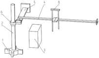
Fig. 1 is a schematic view of an overall structure of a first embodiment of an integrated dimension deviation inspection tool of the present invention;
FIG. 2 is a schematic view of a transverse positioning member according to a first embodiment of the integrated dimension deviation inspection tool of the present invention;
fig. 3 is a schematic view of an overall structure of an embodiment of an integrated tool for checking dimensional deviation according to the present invention;
fig. 4 is a schematic view of an overall structure of a second embodiment of the integrated dimension deviation inspection tool of the present invention;
FIG. 5 is a schematic view of a partial structure of an integrated tool for inspecting dimensional deviation according to a second embodiment of the present invention;
fig. 6 is a schematic view of an overall structure of a third embodiment of the integrated dimension deviation inspection tool of the present invention;
fig. 7 is a schematic view of a local structure of a tool in a third embodiment of the integrated dimension deviation inspection tool during application.
Detailed Description
The following is further detailed by the specific embodiments:
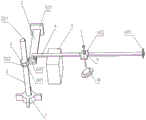
the reference numbers in the drawings of the specification include: the device comprises a base 1, a supporting rod 2, a strip-shaped through groove 201, a positioning boss 202, an auxiliary supporting block 3, a transverse positioning piece 4, a transverse positioning auxiliary plate 401, a measurement positioning part 402, a single-needle positioning hole 403, a double-needle positioning hole 404, a longitudinal positioning piece 5, a longitudinal positioning auxiliary plate 501, a vertical positioning piece 6, an annular part 601, a convex part 602, a single-needle measurement needle 7, a double-needle measurement needle 8, a test block 9 and a measurement auxiliary block 10.
Example one
The embodiment is basically as shown in the attached figures 1 and 3: an integrated dimension deviation checking tool comprises a supporting mechanism, a positioning mechanism and a measuring mechanism.
The supporting mechanism comprises a supporting rod 2, a base 1 and an auxiliary supporting block 3; the base 1 serves to stabilize the support bar 2. The auxiliary supporting block 3 is used for supporting the piece to be measured in an auxiliary mode. Specifically, in this embodiment, a mounting hole is formed in the center of the base 1, a strip-shaped through groove 201 is formed in the outer cylindrical surface of the support rod 2 along the axis direction, the support rod 2 is mounted in the mounting hole, and the bottom surface of the support rod 2 is flush with the bottom surface of the base 1 and is connected with the mounting Kong Wengu through the strip-shaped through groove 201 and a key. The outer cylindrical surface of the support rod 2 is further provided with a positioning boss 202, and in the embodiment, the positioning boss 202 is arranged at the upper part of the support rod 2.
The positioning mechanism comprises a transverse positioning piece 4, a longitudinal positioning piece 5 and a vertical positioning piece 6. The vertical positioning piece 6 is sleeved on the supporting rod 2; specifically, in this embodiment, the vertical positioning element 6 includes an annular portion 601 and a protruding portion 602 that are integrally formed, the annular portion 601 is sleeved on the support rod 2, and an inner diameter of the annular portion 601 is smaller than an inner diameter of the positioning boss 202, and the annular portion 601 can be limited by the positioning boss 202. Moreover, a key is further arranged between the annular part 601 and the strip-shaped through groove 201, so that the vertical positioning piece 6 can be ensured to be fixed and stable.
One end of the transverse positioning piece 4 is connected with the vertical positioning piece 6, the other end of the transverse positioning piece is provided with a transverse positioning auxiliary plate 401 for positioning, in the embodiment, the transverse positioning plate is further provided with a square bulge, and the square bulge can be matched with a piece to be detected subsequently, so that the transverse positioning plate is positioned more reliably. One end of the longitudinal positioning piece 5 is connected with the vertical positioning piece 6, and the other end is provided with a longitudinal positioning auxiliary plate 501 for positioning. Specifically, in this embodiment, a first connection hole is formed in both one end of the transverse positioning element 4 and one end of the longitudinal positioning element 5, and a second connection hole corresponding to the shape and size of the first connection hole is also formed in the protruding portion 602 of the vertical positioning element 6. The first connecting hole is a through hole, and the second connecting hole is a threaded hole and is not a through hole. The longitudinal positioning element 5 and the transverse positioning element 4 can be fixed on the protruding part 602 of the vertical positioning element 6 by matching screws through the first connecting hole and the second connecting hole, so that the transverse positioning element 4 and the longitudinal positioning element 5 are stably arranged.
The measuring mechanism comprises a measuring needle assembly, a measuring auxiliary block 10, a plurality of feelers with specific thicknesses and a testing block 9. The measuring needle assembly is a single-needle measuring needle 7 or a double-needle measuring needle 8, and the measuring needle assembly is the single-needle measuring needle 7 in the embodiment. The test block 9 is arranged above the single-needle positioning hole 403; the center of the test block 9 is provided with a limit hole matched with the single-needle measurement needle 7. Specifically, the single-needle measurement probe 7 includes a probe head and a probe body (i.e., a cylinder and a cone) that are integrally formed, and the diameter of the limit hole is equal to the diameter of the probe body and is smaller than the diameter of the probe head. The body length of the single-needle measurement needle 7 = the thickness of the test block 9 + the maximum theoretical value of the Z-direction of the measurement and positioning section 402 from the thimble hole.
In this embodiment, the single-needle measurement probe 7 may be configured to measure a Z-direction dimensional deviation of a hole to be measured, when a Z-direction standard dimensional tolerance range of the hole to be measured is ± 2mm, and a Z-direction theoretical value of the measurement positioning portion 402 from the thimble hole is a, the Z-direction maximum theoretical value of the measurement positioning portion 402 from the thimble hole is a +2mm, and the length of the single-needle measurement probe 7 = the thickness + a +2mm of the test block 9.
The thickness of the feeler gauge is equal to a third target range value; the third target range value is a maximum clearance value between the lower surface of the measuring needle head and the upper surface of the measuring block 9, which is obtained according to the dimensional tolerance to be measured. In this embodiment, the tolerance of the dimension to be measured in the Z direction is a ± 2mm, the corresponding maximum gap value is 4mm, the thickness of the feeler gauge is set to 4mm, and the dimension deviation inspection can be subsequently performed in cooperation with the single-needle measurement needle 7. If the Z-direction to-be-measured dimension deviation inspection standard needs to be improved, if the inspection tolerance is tightened to be +/-1 mm, the length of the single-needle measurement needle 7 = the thickness of the test block 9 + a +1mm, and the thickness of the corresponding special measurement feeler gauge becomes 2mm.
The transverse positioning piece 4 is further provided with a measurement positioning portion 402, the measurement positioning portion 402 is provided with a positioning hole for limiting the measurement needle, and the measurement needle penetrates through the positioning hole. The positioning holes comprise a single-needle positioning hole 403 arranged in the center of the measurement positioning part 402 and two groups of double-needle positioning holes 404 arranged on the periphery of the central positioning hole; the single set of two-needle positioning holes 404 includes two holes having the same center distance as the center distance of the two-needle measurement needles 8, as shown in fig. 2.
Specifically, the single-needle positioning hole 403 is a square hole, and the size of the square hole is related to the requirement of the dimensional tolerance of the hole to be measured, in this embodiment, the tolerance of the hole to be measured in the X, Y direction is ± 1mm and ± 2mm, respectively, and then the side length of the square hole in the X, Y direction = (the diameter of the single-needle measurement needle 7 + the tolerance range value); the tight inspection can reduce the calculation of a tolerance range value, when the tight inspection is not carried out, the side lengths of the square hole in the X direction and the Y direction are respectively (the diameter of the single-needle measuring needle is 7 + 2) mm and (the diameter of the single-needle measuring needle is 7 + 4) mm, and the center of the square hole is superposed with the theoretical center of the hole to be measured of the piece in the direction of X, Y. The two hole connecting lines of the two groups of the two-needle positioning holes 404 are vertical, and the two hole connecting lines of the two groups of the two-needle positioning holes 404 are respectively parallel to the axis of the transverse positioning piece 4 and the axis of the longitudinal positioning piece 5. Alternatively, in the present embodiment, when the single-needle measurement needle 7 is employed, only the single-needle positioning hole 403 may be provided.
The center of the auxiliary measuring block 10 is provided with a thimble hole for positioning a measuring needle, and the auxiliary measuring block 10 is matched with the shape and size of a hole to be measured of a part to be measured. Specifically, the auxiliary measuring block 10 is a two-section stepped shaft, and the diameter of the first section of the stepped shaft is equal to the diameter of the hole to be measured of the workpiece and smaller than the diameter of the second section of the stepped shaft. The length of the first section of shaft is equal to 1/2 of the depth of the hole to be measured of the piece to be measured. The centre of the top surface of the first section of the shaft is provided with a top pinhole, and the size of the top pinhole is matched with the needle point of the single-needle measuring needle 7.
When the method is specifically applied, the method comprises the following steps:
step 1: placing a piece to be tested, and placing a plurality of auxiliary supporting blocks 3 at proper positions as required to ensure that the piece to be tested is placed stably. And then the auxiliary measuring block 10 is placed in the hole to be measured of the piece to be measured, namely, the first section shaft of the auxiliary measuring block 10 is clamped in the hole to be measured of the piece to be measured.
And 2, step: and adjusting the position of the tool, and adjusting the positions of the bottom surface of the base 1 and the positioning mechanism, so that the transverse positioning auxiliary plate 401 and the vertical positioning auxiliary plate 501 are attached to the surface of the workpiece to be tested, which is used as the design reference of the tool, and the state is maintained.
The test block 9 is placed on the measurement positioning portion 402, the limit hole of the test block 9 is aligned with the single-needle positioning hole 403, the single-needle measurement needle 7 penetrates through the limit hole and the single-needle positioning hole 403 at the same time, the limit hole and the single-needle positioning hole 403 can stably limit the single-needle measurement needle 7, the single-needle measurement needle 7 is assisted to be kept vertical, and detection accuracy is improved.
And 3, step 3: the tip of the single-needle measuring needle 7 is moved to the thimble hole on the auxiliary measuring block 10, and then the feeler gauge is used to check whether the size deviation reaches the standard. Specifically, due to the size of the limiting hole of the testing block 9 and the special length of the single-needle measuring needle 7, when the needle tip of the single-needle measuring needle 7 can move into the thimble hole of the measuring auxiliary block 10, and there is a certain gap between the lower surface of the needle head of the single-needle measuring needle 7 and the upper surface of the testing block 9 (and the lower surface of the testing block 9 needs to be tightly attached to the measuring and positioning portion 402), a feeler with a specific thickness (the thickness is equal to a third target range value) cannot be inserted into the gap, which indicates that the positioning size deviation in the X, Y, Z direction is within the required tolerance range.
Specifically, the principle of the measurement method is that the movement range of the single-needle measurement needle 7 is limited by the dimensions of the test block 9 and the single-needle positioning hole 403 to control the dimensional deviation in the X, Y direction within a tolerance range meeting the use requirement, and then when the dimensional deviation allows the maximum length of the single-needle measurement needle 7 (not counting the needle head thickness), the needle tip can move into the thimble hole on the measurement auxiliary block 10, and whether the dimensional deviation in the Z direction is within the tolerance range is judged by whether the feeler with the thickness equal to the value of the third target range can be inserted into the gap between the lower surface of the measurement needle head and the upper surface of the test block 9 (the lower surface of the test block 9 needs to be attached to the measurement positioning part 402), so that the overall inspection flow is simple, repeated reading and adjustment are not needed, the dimensional deviation inspection of large batches of workpieces can be rapidly completed, the inspection method is not easily affected by manual inspection operation and reading errors, and the inspection result is more intuitive and reliable.
The utility model provides a pair of integral type dimensional deviation inspection frock, the structure sets up succinctly, and the cost of manufacture is lower, can high-efficiently inspect the location and the geometric centre size of the big-and-middle-sized subassembly accessory of batch assembly production, and positioning mechanism can use a (subassembly) appearance that awaits measuring as inspection location benchmark, and the size inspection can be accomplished fast to the measurement needle and the clearance gauge of frock cooperation specific dimension, easy operation, and the inspection is high-efficient, and the inspection result is directly perceived.
Particularly, different from a conventional dimension deviation inspection tool, the conventional tool usually requires higher reading precision, and repeatedly leveling and aligning a to-be-measured piece is also required during inspection. In addition, for dimension inspection in batch production, each piece is not required to be accurately measured and read actually, and the piece is qualified through verification, so that the high-precision reading of the existing tool is waste of inspection cost actually. And this scheme then sets out to this type of actual scene, designed one set of new can with the abundant inspection frock that matches of batch production scene, the inspection thinking of this frock also sets out from the more qualified angle of inspection of laminating reality, the limited of special size has been carried out to the subassembly among the measuring mechanism, the range of movement of control measuring pin is injectd through the size, whether the clearance gauge of rethread specific thickness can insert, judge whether Z direction dimensional deviation is in the tolerance range, whether can the visual display inspection qualified, need not the reading, timing, it is more efficient to inspect.
Example two
As shown in fig. 4 and 5, an integrated dimension deviation checking tool adjusts the measurement probe assembly based on the first embodiment.
In this embodiment, the measurement needle assembly is a double-needle measurement needle 8; the double-needle measurement probe 8 comprises a first measurement probe and a second measurement probe which are equal in length, and the lengths of the probe bodies (namely, the cylinder and the cone) of the first measurement probe and the second measurement probe are enough to enable the probe tips of the measurement probes to contact the surface to be measured of the piece to be measured.
In particular, the double needle measurement tip 8 also comprises a measurement tip connection block. The first measuring needle and the second measuring needle are arranged on the measuring needle connecting block and are integrally connected with the measuring needle connecting block. The first measurement tip axis and the second measurement tip axis are spaced apart by 70mm. Correspondingly, the center-to-center distance between the two holes of the single set of two-pin positioning holes 404 is also 70mm.
The double-needle measuring needle 8 with equal length can be used for measuring the verticality between the surface of the piece to be measured and the XZ plane. When the method is specifically applied, the method comprises the following steps:
step 1: placing the piece to be tested, and placing a plurality of auxiliary supporting blocks 3 at proper positions as required to ensure that the piece to be tested is placed stably.
Step 2: and adjusting the position of the tool, and adjusting the positions of the bottom surface of the base 1 and the positioning mechanism, so that the transverse positioning auxiliary plate 401 and the vertical positioning auxiliary plate 501 are attached to the surface of the workpiece to be tested, which is used as the design reference of the tool, and the state is maintained.
And step 3: the double-needle measurement needles 8 with equal length are inserted into the single-set double-needle positioning hole 404, and the needle tip of one of the double-needle measurement needles 8 is made to contact with the surface to be measured of the object to be measured.
And 4, step 4: and (4) checking whether the dimensional deviation meets the standard by adopting a feeler with a specific thickness. Specifically, for example, if the tip of the first measurement probe is in contact with the surface to be measured of the object, and the feeler with a specific thickness cannot be inserted into the gap between the second measurement probe and the surface to be measured of the object, it indicates that the perpendicularity of the surface and the XZ plane is within the required range.
Specifically, the feeler gauge thickness is equal to a second target range value; and the second target range value is a maximum clearance value between the surface of the to-be-measured piece and the tip of the measuring needle obtained according to the to-be-measured dimensional tolerance. In this embodiment, the standard dimension deviation range (i.e., the tolerance of the dimension to be measured), i.e., the verticality requirement, is ± 1mm, the maximum clearance value between the surface of the to-be-measured object and the tip of the measurement probe is 2mm, and the thickness of the feeler gauge is 2mm.
The principle of the measuring mode is that whether the feeler gauge with the thickness not larger than the tolerance range of the allowable verticality can be inserted into the contact gap between the isometric measuring needle and the surface of the piece to be measured or not is judged, whether the verticality between the surface of the piece to be measured and the XZ plane is in the tolerance range or not is further judged, the detection is reliable, and the detection flow is simple and efficient.
The integral type dimensional deviation inspection frock that this embodiment provided, the structure sets up succinctly, can realize using easy operation to the high-efficient inspection of surface verticality, and the inspection result is directly perceived, and the inspection effect is better.
EXAMPLE III
As shown in fig. 6 and 7, an integrated dimension deviation checking tool adjusts a measurement probe assembly based on the first embodiment.
In this embodiment, the measurement needle assembly is a double-needle measurement needle 8; the two-tip measurement tip 8 includes a first measurement tip and a second measurement tip that are not equal in length. In particular, the double-needle measurement tip 8 further comprises a measurement tip connection block. The first measuring needle and the second measuring needle are arranged on the measuring needle connecting block and are integrally connected with the measuring needle connecting block. The first measurement tip axis and the second measurement tip axis are spaced apart by 70mm. Correspondingly, the center-to-center distance between the two holes of the single set of two-pin positioning holes 404 is also 70mm.
And the length of the longer one of the first and second measurement needles (i.e. cylinder + cone) enables the tip of the measurement needle to contact the surface to be measured of the piece to be measured. The length difference value of the first measurement needle and the second measurement needle = a first target range value; the first target range value is a length value of the opposite side when the angle to be measured is at the maximum size deviation angle and the length of the leading side is determined in the tangent trigonometric function. Specifically, if the angle requirement between the surface to be measured of the object to be measured and the XY plane is β ± 2 °, the axial distance value between the two measurement needles is 70mm, and in this embodiment, the axial distance value between the two measurement needles is a neck side length value, in the tangent trigonometric function, the length value of the opposite side when the angle to be measured is at the maximum dimension deviation angle and the neck side length is determined (70 mm) is =70 × tan (β + 2) mm.
The double-needle measuring needles 8 with different lengths can be used for measuring the angle tolerance of the surface of the piece to be measured and the XZ plane. When the method is specifically applied, the method comprises the following steps:
step 1: placing the piece to be tested, and placing a plurality of auxiliary supporting blocks 3 at proper positions as required to ensure that the piece to be tested is placed stably.
Step 2: and adjusting the position of the tool, and adjusting the positions of the bottom surface of the base 1 and the positioning mechanism, so that the transverse positioning auxiliary plate 401 and the vertical positioning auxiliary plate 501 are attached to the surface of the workpiece to be tested, which is used as the design reference of the tool, and the state is maintained.
And step 3: the double-needle measurement needles 8 with different lengths are inserted into the single-group double-needle positioning hole 404, and the double-needle measurement needles 8 move downwards in the Z direction until any measurement needle in the double-needle measurement needles 8 contacts the surface to be measured of the piece to be measured, that is, the needle point of one measurement needle in the double-needle measurement needles 8 contacts the surface to be measured of the piece to be measured, and here, the first measurement needle with a relatively longer length should contact the surface to be measured of the piece to be measured first.
And 4, step 4: and (4) checking whether the dimensional deviation meets the standard by adopting a feeler with a specific thickness. Specifically, the tip of the first measuring probe is in contact with the surface to be measured of the object to be measured, and the feeler with a specific thickness cannot be inserted into the gap between the second measuring probe and the surface to be measured of the object to be measured, which indicates that the angular deviation between the surface and the XZ plane is within the required range.
Specifically, the feeler gauge thickness is equal to a second target range value; and the second target range value is the maximum clearance value between the surface of the to-be-measured piece and the tip of the measuring needle obtained according to the to-be-measured dimensional tolerance. The maximum gap value meeting the angle requirement of β ± 2 ° in this example =70 × [ tan (β + 2) -tan (β -2) ] mm, where 70 denotes the axial distance value of the two measuring needles.
The principle of the measuring mode is that the needle point of a longer measuring needle is used as a reference, after the distance between the two measuring needles in the X direction is fixed, the height difference of the two measuring needle points when the allowable angle deviation is maximum is calculated through a trigonometric function to determine the length of the shorter measuring needle, and the height difference between the maximum allowable angle deviation and the minimum allowable angle deviation is calculated through the trigonometric function again to determine the length difference of the two measuring needles and the thickness of the measuring feeler, so that whether the angle between the surface to be measured and the XY plane is within the tolerance range or not is judged, the inspection is reliable, and the inspection process is simple and efficient.
The integral type size deviation inspection frock that this embodiment provided, the structure sets up succinctly, can realize the high-efficient inspection to the angle deviation, uses easy operation, and the inspection result is directly perceived, and the inspection effect is better.
The above description is only for the embodiments of the present invention, and the common general knowledge of the known specific structures and characteristics in the schemes is not described herein too much, and those skilled in the art will know all the common technical knowledge in the technical field of the present invention before the application date or the priority date, can know all the prior art in this field, and have the ability to apply the conventional experimental means before this date, and those skilled in the art can combine their own ability to perfect and implement the schemes, and some typical known structures or known methods should not become obstacles for those skilled in the art to implement the present application. It should be pointed out, for the technical personnel in this field, in the utility model relates to with the location benchmark of the design frock of measured piece appearance itself, again through directly or calculate the clearance that produces of size when two limit deviation, add the technical thinking that whether special size inspection hole or specific thickness clearance gauge inspection deviation meet the requirements, can also make a plurality of deformations and improvements, these should also be regarded as the utility model's protection scope, these can not influence the effect of the implementation of the utility model and the practicality of patent.
Claims (9)
1. An integrated dimension deviation inspection tool is characterized by comprising a supporting mechanism, a positioning mechanism and a measuring mechanism; the support mechanism comprises a support rod; the positioning mechanism comprises a transverse positioning piece, a longitudinal positioning piece and a vertical positioning piece; the measuring mechanism comprises a measuring needle assembly; the measuring needle assembly is a single-needle measuring needle or a double-needle measuring needle;
the vertical positioning piece is sleeved on the supporting rod; one end of the transverse positioning piece is connected with the vertical positioning piece, and the other end of the transverse positioning piece is provided with a transverse positioning auxiliary plate for positioning; one end of the longitudinal positioning piece is connected with the vertical positioning piece, and the other end of the longitudinal positioning piece is provided with a longitudinal positioning auxiliary plate for positioning;
the transverse positioning piece is also provided with a measuring positioning part, the measuring positioning part is provided with a positioning hole for limiting a measuring needle, and the measuring needle penetrates through the positioning hole; the positioning holes comprise a single-needle positioning hole arranged in the center of the measuring positioning part and two groups of double-needle positioning holes arranged on the periphery of the central positioning hole; the single group of the double-needle positioning holes comprise two holes with the center distance equal to that of the double-needle measuring needles.
2. The integrated dimensional deviation checking tool according to claim 1, wherein the measuring needle assembly is a single-needle measuring needle; the measuring mechanism further comprises a testing block; the test block is arranged above the single-needle positioning hole; the center of the test block is provided with a limit hole matched with the single-needle measurement needle.
3. The integrated dimension deviation inspection tool according to claim 2, wherein the measuring mechanism further comprises a measuring auxiliary block; the center of the auxiliary measuring block is provided with a thimble hole for positioning a measuring needle, and the auxiliary measuring block is matched with the shape and the size of a hole to be measured of the piece to be measured; and the length of the single-needle measuring needle = the thickness of the test block + the maximum theoretical value of the distance of the measuring and positioning part from the thimble hole in the Z direction.
4. The integrated dimensional deviation inspection tool of claim 1, wherein the measurement needle assembly is a double-needle measurement needle; the double-needle measurement tip includes a first measurement tip and a second measurement tip that are equal in length.
5. The integrated dimensional deviation checking tool according to claim 1, wherein the measuring needle assembly is a double-needle measuring needle; the double-needle measuring needle comprises a first measuring needle and a second measuring needle which are not equal in length; and the length difference between the first measuring needle and the second measuring needle = a first target range value; the first target range value is a length value of the opposite side when the angle to be measured is at the maximum size deviation angle and the length of the leading side is determined in the tangent trigonometric function.
6. The integrated dimensional deviation inspection tool according to claim 1, wherein the support mechanism further comprises a base; the base is used to stabilize the support bar.
7. The integrated dimensional deviation inspection tool according to claim 6, wherein the support mechanism further comprises an auxiliary support block; the auxiliary supporting block is used for supporting the piece to be measured in an auxiliary mode.
8. The integrated dimensional deviation inspection tool according to claim 5, wherein the measuring mechanism further comprises a feeler; when the measuring needle assembly is a double-needle measuring needle, the thickness of the feeler gauge is equal to a second target range value; and the second target range value is a maximum clearance value between the surface of the to-be-measured piece and the tip of the measuring needle obtained according to the to-be-measured dimensional tolerance.
9. The integrated dimensional deviation inspection tool according to claim 3, wherein the measuring mechanism further comprises a feeler; when the measuring needle assembly is a single-needle measuring needle, the thickness of the feeler gauge is equal to a third target range value; and the third target range value is the maximum clearance value between the lower surface of the measuring needle head and the upper surface of the measuring block obtained according to the dimensional tolerance to be measured.
Priority Applications (1)
| Application Number | Priority Date | Filing Date | Title |
|---|---|---|---|
| CN202223074704.2U CN218566354U (en) | 2022-11-18 | 2022-11-18 | Integral type size deviation inspection frock |
Applications Claiming Priority (1)
| Application Number | Priority Date | Filing Date | Title |
|---|---|---|---|
| CN202223074704.2U CN218566354U (en) | 2022-11-18 | 2022-11-18 | Integral type size deviation inspection frock |
Publications (1)
| Publication Number | Publication Date |
|---|---|
| CN218566354U true CN218566354U (en) | 2023-03-03 |
Family
ID=85325426
Family Applications (1)
| Application Number | Title | Priority Date | Filing Date |
|---|---|---|---|
| CN202223074704.2U Active CN218566354U (en) | 2022-11-18 | 2022-11-18 | Integral type size deviation inspection frock |
Country Status (1)
| Country | Link |
|---|---|
| CN (1) | CN218566354U (en) |
-
2022
- 2022-11-18 CN CN202223074704.2U patent/CN218566354U/en active Active
Similar Documents
| Publication | Publication Date | Title |
|---|---|---|
| CN103822565B (en) | A kind of pitch-row comparing measuring apparatus | |
| CN109341494A (en) | The quickly device of detection inner bore chamfering depth | |
| CN102589377B (en) | Measuring instrument testing fixture for length measuring machine | |
| CN112146553B (en) | Design method and use method of inner inclined hole position size measuring device | |
| CN207936891U (en) | A kind of instrument for measuring pitch diameter of internal thread | |
| CN113074628B (en) | Device and method for checking trimming molded surface | |
| CN218566354U (en) | Integral type size deviation inspection frock | |
| CN110779418A (en) | Method for measuring length of cone on line by double meters | |
| US4571838A (en) | Direct readout centerline measuring device and process | |
| CN116086283A (en) | Probe size detection table and use method | |
| CN115900475A (en) | Integral type size deviation inspection frock | |
| CN105157639A (en) | Combined positioning device and positioning method | |
| JP6742846B2 (en) | Position gauge, centering device and centering method | |
| CN109724497B (en) | Method for online detecting radius value of inner sphere | |
| CN212253911U (en) | Axial dimension measuring tool | |
| CN210070789U (en) | Detection device for detecting position accuracy of connecting rod side surface and cover seat surface | |
| CN209085507U (en) | The device for fast detecting of inner bore chamfering depth | |
| CN201476746U (en) | Vertical hole pitch measurement device | |
| CN210952615U (en) | Center distance type multi-parameter detection device | |
| KR20160023401A (en) | Device for measuring squareness | |
| CN219798127U (en) | Precision step excircle height measuring clamp | |
| CN108871161B (en) | Detection tool assembly for detecting angle of small plane and use method thereof | |
| CN114046713B (en) | Leveling device suitable for height difference of inner and outer parts | |
| CN218776840U (en) | Manual detection device for deformation point position of inner wall of tubular pile die | |
| CN220153436U (en) | Comprehensive detection tool for motor iron core |
Legal Events
| Date | Code | Title | Description |
|---|---|---|---|
| GR01 | Patent grant | ||
| GR01 | Patent grant |