CN218557834U - Plastic mould - Google Patents
Plastic mould Download PDFInfo
- Publication number
- CN218557834U CN218557834U CN202222771510.1U CN202222771510U CN218557834U CN 218557834 U CN218557834 U CN 218557834U CN 202222771510 U CN202222771510 U CN 202222771510U CN 218557834 U CN218557834 U CN 218557834U
- Authority
- CN
- China
- Prior art keywords
- mold
- insert
- plastic
- positioning
- rotating
- Prior art date
- Legal status (The legal status is an assumption and is not a legal conclusion. Google has not performed a legal analysis and makes no representation as to the accuracy of the status listed.)
- Active
Links
Images


Landscapes
- Moulds For Moulding Plastics Or The Like (AREA)
- Injection Moulding Of Plastics Or The Like (AREA)
Abstract
The utility model discloses a plastic mould, including relative first framed and the second framed that sets up, be equipped with the mouth of moulding plastics on the first framed, plastic mould includes: the die core component is arranged between the first die frame and the second die frame and is provided with at least two groups of cavities which are arranged in a separated mode; the insert assembly comprises two inserts which are oppositely arranged in the mold core assembly, each insert comprises a fixing portion and a rotating portion, a first flow channel communicated with the injection molding opening is formed in the fixing portion, a second flow channel communicated with the first flow channel is formed in the rotating portion, and the rotating portion rotates to enable one group of the cavities to be communicated with the second flow channel. The utility model discloses can design two kinds and above products simultaneously in same set of mould, practice thrift the manufacturing cost of mould, avoid dismantling the change mould, reduce invalid man-hour, be favorable to improving production efficiency.
Description
Technical Field
The utility model belongs to the technical field of injection moulding, concretely relates to plastic mould.
Background
In actual production, one set of plastic molds can only produce one product, and when an order of one product is finished, if other products are required to be produced, the currently used molds are detached from a forming machine and another set of molds are installed again. When two or more products are produced in the mode, an operator needs to disassemble the die, so that invalid working hours of reducing the temperature of the die, replacing the die, heating the die and the like are increased, and the production efficiency of enterprises is reduced; meanwhile, different molds are needed to meet the requirements of producing different products, so that the manufacturing cost of the molds is increased.
Therefore, it is desirable to provide a plastic mold for solving the above problems.
SUMMERY OF THE UTILITY MODEL
In view of the above, the present invention is directed to a plastic mold.
In order to achieve the above object, an embodiment of the present invention provides the following technical solutions:
the utility model provides a plastic mould, plastic mould includes relative first framed and the second framed that sets up, be equipped with the mouth of moulding plastics on the first framed, plastic mould includes:
the utility model provides a plastic mould, plastic mould includes relative first framed and the second framed that sets up, be equipped with the mouth of moulding plastics on the first framed, its characterized in that, plastic mould includes:
the die core assembly is arranged between the first die frame and the second die frame and is provided with at least two sets of cavities which are arranged in a separated mode;
the insert assembly comprises two inserts which are oppositely arranged in the mold core assembly, each insert comprises a fixing part and a rotating part, a first flow passage communicated with the injection molding opening is formed in the fixing part, a second flow passage communicated with the first flow passage is formed in the rotating part, and the rotating part rotates to enable one group of the cavities to be communicated with the second flow passage.
In one embodiment, the mold core assembly includes a first mold core fixedly installed in the first mold frame and a second mold core fixedly installed in the second mold frame, and the first mold core and the second mold core are fixedly installed to enclose the cavity.
In one embodiment, the cavity includes a molding cavity and a third runner communicated with the molding cavity.
In one embodiment, the insert assembly includes a first insert fixedly mounted in the first mold core and a second insert fixedly mounted in the second mold core, the first insert and the second insert being fixedly mounted.
In one embodiment, the first insert includes a first fixing portion and a first rotating portion, the first fixing portion includes a first protruding portion fixedly mounted on the first mold frame and a first main body portion fixedly mounted in the first mold core, and the first rotating portion is mounted on the first main body portion;
the second insert comprises a second fixing portion and a second rotating portion, the second fixing portion comprises a second protruding portion and a second main body portion, the second protruding portion and the second main body portion are fixedly installed in the second mold core, and the second rotating portion is installed on the second main body portion.
In one embodiment, the first rotating portion is provided with a first groove communicated with the first flow passage, the second rotating portion is provided with a second groove communicated with the first flow passage, and the first groove and the second groove enclose to form a second flow passage.
In one embodiment, the first mold core is provided with a first positioning member, the first protrusion is provided with at least two first positioning holes and/or first positioning surfaces, and the first positioning member is installed in cooperation with the first positioning holes and/or the first positioning surfaces.
In an embodiment, a second positioning element is disposed on the second mold frame, the second protruding portion has at least two second positioning holes and/or second positioning surfaces, and the second positioning element is mounted in cooperation with the second positioning holes and/or the second positioning surfaces.
In one embodiment, the first rotating portion is provided with a first clamping portion, and the second rotating portion is provided with a second clamping portion.
In one embodiment, the first clamping portion includes a plurality of connecting holes, and the second clamping portion includes a plurality of connecting holes; and/or the presence of a gas in the gas,
the first clamping portion comprises a plurality of connecting holes or lugs, and the second clamping portion comprises a plurality of lugs or connecting holes.
The utility model discloses following beneficial effect has:
the utility model provides a plastic mould, which can simultaneously design two or more products in the same mould, thus saving the manufacturing cost of the mould;
the utility model discloses simple structure only needs to be through the rotation portion on the rotatory mold insert subassembly, can freely switch over the different products of production, has avoided dismantling the change mould, has effectively reduced invalid man-hour such as mould cooling, dismouting, heating, has improved the production efficiency of enterprise, is favorable to extensively promoting.
Drawings
In order to more clearly illustrate the embodiments of the present invention or the technical solutions in the prior art, the drawings used in the description of the embodiments or the prior art will be briefly described below, it is obvious that the drawings in the description below are only some embodiments described in the present invention, and for those skilled in the art, other drawings can be obtained according to the drawings without creative efforts.
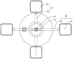
Fig. 1 is a schematic structural view of a plastic mold according to an embodiment of the present invention;
fig. 2 is a schematic structural view of an insert assembly according to an embodiment of the present invention;
fig. 3 is a schematic bottom view of a first insert according to an embodiment of the present invention;
fig. 4 is a schematic top view of a second insert according to an embodiment of the present invention;
fig. 5 is a schematic bottom view of a second insert according to an embodiment of the present invention;
FIG. 6 is an enlarged view of a portion of the structure at A in FIG. 1;
FIG. 7 is an enlarged view of a portion of the structure shown at B in FIG. 1;
FIG. 8 is a schematic view of a structure of the first cavity communicating with the injection port according to an embodiment of the present invention;
fig. 9 is a schematic structural view illustrating the second cavity being communicated with the injection molding opening according to an embodiment of the present invention.
Detailed Description
To make the purpose, technical solution and advantages of the embodiments of the present invention clearer, the attached drawings in the embodiments of the present invention are combined to clearly and completely describe the technical solution in the embodiments of the present invention, and obviously, the described embodiments are part of the embodiments of the present invention, rather than all embodiments. The components of the embodiments of the present invention generally described and illustrated in the figures herein may be arranged and designed in a wide variety of different configurations.
Thus, the following detailed description of the embodiments of the invention, as presented in the figures, is not intended to limit the scope of the invention, as claimed, but is merely representative of selected embodiments of the invention. Based on the embodiments in the present invention, all other embodiments obtained by a person skilled in the art without creative efforts belong to the protection scope of the present invention.
It should be noted that: like reference numbers and letters refer to like items in the following figures, and thus, once an item is defined in one figure, it need not be further defined and explained in subsequent figures.
In the description of the embodiments of the present invention, it should be understood that the terms "center", "upper", "lower", "left", "right", "vertical", "horizontal", "inner", "outer", etc. indicate the orientation or positional relationship based on the orientation or positional relationship shown in the drawings, or the orientation or positional relationship that the product of this application is usually placed when in use, or the orientation or positional relationship that a person skilled in the art usually understands, and are only for convenience of describing the present invention and simplifying the description, but do not indicate or imply that the device or element referred to must have a specific orientation, be constructed in a specific orientation, and be operated, and therefore should not be construed as limiting the present invention.
In the description of the embodiments of the present invention, it should be further noted that unless otherwise explicitly stated or limited, the terms "disposed," "mounted," "connected," and "connected" are to be construed broadly and may include, for example, a fixed connection, a detachable connection, or an integral connection; they may be connected directly or indirectly through intervening media, or they may be interconnected between two elements. The specific meaning of the above terms in the present invention can be understood in specific cases to those skilled in the art.
In the description of the embodiments of the present invention, it should be noted that the terms "first", "second", and the like as used herein do not mean to refer to an order or sequence, and are not intended to limit the present disclosure, but only to distinguish components or operations described in the same technical terms.
It should be noted that, in the present invention, the embodiments and features of the embodiments may be combined with each other without conflict.
The technical solution of the present invention will be described with reference to the accompanying drawings.
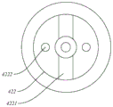
Referring to fig. 1, a plastic mold according to an embodiment of the present invention includes a first mold frame 1, a second mold frame 2, a mold insert assembly 3, and a mold insert assembly 4.
Specifically, the first mold frame 1 and the second mold frame 2 in this embodiment are disposed opposite to each other, and the first mold frame 1 is provided with an injection port 11, and the injection port 11 is disposed to facilitate injecting resin into a cavity of a plastic mold.
The mold core assembly 3 in this embodiment is disposed between the first mold frame 1 and the second mold frame 2, and at least two sets of cavities 5 and 6 are formed between the mold core assemblies 3. The cavities 5, 6 in this embodiment are two sets, but the invention is not limited thereto, and three sets may be provided for producing three products, as will be appreciated and understood by those skilled in the art.
The insert assembly 4 in this embodiment includes two inserts oppositely disposed in the mold core assembly 3, the insert includes a fixing portion and a rotating portion, the fixing portion is provided with a first flow channel 43 communicated with the injection port 11, the rotating portion is provided with a second flow channel 44 communicated with the first flow channel 43, and the rotating portion rotates to communicate one of the cavities 5 and 6 with the second flow channel 44.
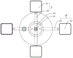
With the design, referring to fig. 8 and 9, the present embodiment can simultaneously design two or more products in the same set of mold, thereby saving the manufacturing cost of the mold; meanwhile, the position of the second flow channel 44 is changed by rotating the rotating part in the insert assembly 4, so that one group of the two cavities 5 and 6 is communicated with the second flow channel 44, and the other group of the cavities 5 and 6 is communicated with the injection port 11 through the arrangement of the first flow channel 43 and the second flow channel 44, so that the resin can flow through the first flow channel 43 and the second flow channel 44 to enter the cavities 5 and 6 after being injected from the injection port 11, and a product is produced.
In this embodiment, two sets of cavities 5 and 6 are separately formed in the mold insert assembly 3, and each set of cavities 5 and 6 is used for producing one product, so that after resin is injected into the plastic mold in this embodiment, at least two different products can be produced by changing the position of the second runner 44.
Specifically, the mold core assembly 3 includes a first mold core 31 fixedly installed in the first mold frame 1 and a second mold core 32 fixedly installed in the second mold frame 2, and the first mold core 31 and the second mold core 32 enclose to form the cavities 5 and 6. Through setting up relative setting and the first mould benevolence 31 and the second mould benevolence 32 of cooperation installation, can realize quick installation, improve the installation effectiveness, simultaneously because the shape of product, specification etc. are comparatively complicated, form cavity 5, 6 through the cooperation installation of first mould benevolence 31 and the second mould benevolence 32, the product that accords with the demand can comparatively be produced to this kind of design, and the facilitate promotion.
Further, the cavities 5, 6 in the present embodiment include the molding cavities 51, 61 and the third flow passages 52, 62. The resin injected into the inner part can be designed according to the shapes of the molding cavities 51 and 61 to produce products with specified shapes, specifications and sizes. Meanwhile, the third flow channels 52 and 62 are designed to be in contact with the second flow channel 44 on one hand, and on the other hand, ejection structures such as ejector pins can be arranged at the lower parts of the third flow channels for ejecting the formed products out of the cavities 5 and 6 to achieve the purpose of demolding.
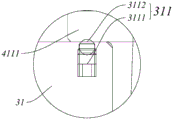
Referring to fig. 2, the insert assembly 4 in this embodiment includes a first insert 41 fixedly installed in the first mold core 31 and a second insert 42 fixedly installed in the second mold core 32, and the first insert 41 and the second insert 42 are fixedly installed. According to the design, the insert component 4 is favorably and fixedly arranged in the die core component 3, the installation speed is high, and the fixation is firm.
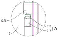
Specifically, the first insert 41 in this embodiment includes a first fixing portion 411 and a first rotating portion 412, the first fixing portion 411 includes a first protrusion portion 4111 fixedly mounted on the first mold frame 1 and a first main body portion 4112 fixedly mounted in the first mold core 31, and the first rotating portion 412 is mounted on the first main body portion 4112. The second insert 42 includes a second fixing portion and a second rotating portion 422, the second fixing portion includes a second protruding portion 4211 and a second main body portion 4212 fixedly installed in the second mold core 32, and the second rotating portion 422 is installed on the second main body portion 4212.
Referring to fig. 3 and 4, first rotating portion 412 is provided with first groove 4121 communicating with first flow channel 43, second rotating portion 422 is provided with second groove 4221 communicating with first flow channel 43, and first groove 4121 and second groove 4221 enclose to form second flow channel 44.
According to the design, the first rotating part 412 and the second rotating part 422 can be rotated respectively, the rotating angles of the first rotating part 412 and the second rotating part 422 are consistent, and when the specified position is reached, the second runner 44 formed by enclosing the first groove 4121 and the second groove 4221 can be communicated with the third runners 52, 62 of one group of the cavities 5, 6, so that the molding cavities 51, 61 are communicated with the injection port 11.
For positioning the first insert 41, referring to fig. 3 and 5, the first mold core 31 of the present embodiment is provided with a first positioning member 311, the first protrusion 4111 is provided with at least two first positioning holes 41111, 42111 and/or first positioning surfaces, and the first positioning member 311 is installed in cooperation with the first positioning holes 41111, 42111 and/or the first positioning surfaces.
The specific positioning method comprises the following steps: the first positioning member 311 includes a first elastic member 3111 disposed in the first mold core 31 and a first ball 3112 connected to the first elastic member 3111 and partially exposed out of the first mold core 31, when the first rotating portion 412 rotates to a state where the first groove 4121 is communicated with the third flow channel 5262, the first ball 3112 contacts one of the first positioning holes 41111, 42111 and/or the first positioning surface under the action of the first elastic member 3111, so as to position the whole first mold insert 41 and prevent the first mold insert 41 from rotating during production.
In order to position the second insert 42, the second mold frame 2 of the present embodiment is provided with a second positioning element 21, the second protrusion 4211 is provided with at least two second positioning holes 41111, 42111 and/or a second positioning surface, and the second positioning element 21 is installed in cooperation with the second positioning holes 41111, 42111 and/or the second positioning surface.
The specific positioning method comprises the following steps: the second positioning member 21 includes a second elastic member 211 disposed in the second mold frame 2 and a second ball 212 connected to the second elastic member 211 and partially exposed from the second mold frame 2, and when the second rotating portion 422 rotates to a state where the second groove 4221 is communicated with the third flow channel 5262, the second ball 212 contacts with one of the second positioning holes 41111, 42111 and/or the second positioning surface under the action of the second elastic member 211, so as to position the whole second insert 42 and prevent the second insert 42 from rotating during production. For the convenience of rotation, in the present embodiment, the first rotating portion 412 is provided with a first engaging portion 4122, and the second rotating portion 422 is provided with a second engaging portion 4222.
With this design, after one product is produced, the first insert 41 and the second insert 42 can be rotated by a wrench or other tool to connect the second flow channel 44 with the other set of cavities 5 and 6, so that the plastic mold in this embodiment can produce another product.
Specifically, the first click portion 4122 in the present embodiment includes two connection holes, and the second click portion 4222 includes two connection holes. According to the design, the first rotating part 412 or the second rotating part 422 can be rotated by clamping the two connecting holes through a wrench.
However, the utility model is not limited to this, and a connecting hole can be designed, only the shape of the connecting hole is non-circular; the first clamping portion 4122 can be set as a connecting hole, and the second clamping portion 4222 can be set as a bump installed in cooperation with the connecting hole; or the first clamping portion 4122 may be a protrusion, and the second clamping portion 4222 may be a connection hole; in any of these designs, the first or second rotation portion 412 or 422 can be rotated by an external tool engaged with the first or second locking portion 4122 or 4222. As would be acceptable and understood by those skilled in the art.
According to the technical scheme provided by the utility model, the utility model discloses following beneficial effect has:
the utility model provides a plastic mould, which can simultaneously design two or more products in the same mould, thus saving the manufacturing cost of the mould;
the utility model discloses simple structure only needs to be through the rotation portion on the rotatory mold insert subassembly, can freely switch over the different products of production, has avoided dismantling the change mould, has effectively reduced invalid man-hour such as mould cooling, dismouting, heating, has improved the production efficiency of enterprise, is favorable to extensively promoting.
It is obvious to a person skilled in the art that the invention is not restricted to details of the above-described exemplary embodiments, but that it can be implemented in other specific forms without departing from the spirit or essential characteristics of the invention. The present embodiments are therefore to be considered in all respects as illustrative and not restrictive, the scope of the invention being indicated by the appended claims rather than by the foregoing description, and all changes which come within the meaning and range of equivalency of the claims are therefore intended to be embraced therein. Any reference sign in a claim should not be construed as limiting the claim concerned.
Furthermore, it should be understood that although the present description refers to embodiments, not every embodiment may contain only a single embodiment, and such description is for clarity only, and those skilled in the art should integrate the description, and the embodiments may be combined as appropriate to form other embodiments understood by those skilled in the art.
Claims (10)
1. The utility model provides a plastic mould, plastic mould includes relative first framed and the second framed that sets up, be equipped with the mouth of moulding plastics on the first framed, its characterized in that, plastic mould includes:
the die core component is arranged between the first die frame and the second die frame and is provided with at least two sets of cavities which are arranged separately;
the insert assembly comprises two inserts which are oppositely arranged in the mold core assembly, each insert comprises a fixing part and a rotating part, a first flow passage communicated with the injection molding opening is formed in the fixing part, a second flow passage communicated with the first flow passage is formed in the rotating part, and the rotating part rotates to enable one group of the cavities to be communicated with the second flow passage.
2. The plastic mold of claim 1, wherein the mold insert assembly comprises a first mold insert fixedly mounted in the first mold frame and a second mold insert fixedly mounted in the second mold frame, the first mold insert and the second mold insert being fixedly mounted to enclose the cavity.
3. The plastic mold of claim 2, wherein the cavity comprises a molding cavity and a third runner in communication with the molding cavity.
4. The plastic mold of claim 2, wherein the insert assembly includes a first insert fixedly mounted in the first mold core and a second insert fixedly mounted in the second mold core, the first and second inserts being fixedly mounted.
5. The plastic mold as recited in claim 4, wherein the first insert includes a first fixed portion and a first rotating portion, the first fixed portion including a first protrusion fixedly mounted on the first mold frame and a first body portion fixedly mounted in the first mold core, the first rotating portion being mounted on the first body portion;
the second insert comprises a second fixing portion and a second rotating portion, the second fixing portion comprises a second protruding portion and a second main body portion, the second protruding portion and the second main body portion are fixedly installed in the second mold core, and the second rotating portion is installed on the second main body portion.
6. The plastic mold as claimed in claim 5, wherein the first rotating portion has a first groove connected to the first runner, the second rotating portion has a second groove connected to the first runner, and the first groove and the second groove enclose a second runner.
7. The plastic mold according to claim 5, wherein the first mold core has a first positioning element, the first protrusion has at least two first positioning holes and/or first positioning surfaces, and the first positioning element is mounted in cooperation with the first positioning holes and/or the first positioning surfaces.
8. The plastic mold as claimed in claim 5, wherein a second positioning element is disposed on the second mold frame, the second protrusion has at least two second positioning holes and/or second positioning surfaces, and the second positioning element is mounted in cooperation with the second positioning holes and/or second positioning surfaces.
9. The plastic mold as claimed in claim 5, wherein the first rotating portion is provided with a first engaging portion, and the second rotating portion is provided with a second engaging portion.
10. The plastic mold as claimed in claim 9, wherein the first engaging portion includes a plurality of connecting holes, and the second engaging portion includes a plurality of connecting holes; and/or the presence of a gas in the gas,
the first clamping portion comprises a plurality of connecting holes or lugs, and the second clamping portion comprises a plurality of lugs or connecting holes.
Priority Applications (1)
| Application Number | Priority Date | Filing Date | Title |
|---|---|---|---|
| CN202222771510.1U CN218557834U (en) | 2022-10-20 | 2022-10-20 | Plastic mould |
Applications Claiming Priority (1)
| Application Number | Priority Date | Filing Date | Title |
|---|---|---|---|
| CN202222771510.1U CN218557834U (en) | 2022-10-20 | 2022-10-20 | Plastic mould |
Publications (1)
| Publication Number | Publication Date |
|---|---|
| CN218557834U true CN218557834U (en) | 2023-03-03 |
Family
ID=85317272
Family Applications (1)
| Application Number | Title | Priority Date | Filing Date |
|---|---|---|---|
| CN202222771510.1U Active CN218557834U (en) | 2022-10-20 | 2022-10-20 | Plastic mould |
Country Status (1)
| Country | Link |
|---|---|
| CN (1) | CN218557834U (en) |
-
2022
- 2022-10-20 CN CN202222771510.1U patent/CN218557834U/en active Active
Similar Documents
| Publication | Publication Date | Title |
|---|---|---|
| CN218557834U (en) | Plastic mould | |
| CN212045724U (en) | Improved injection mold | |
| CN214082630U (en) | Spring cavity type injection mold | |
| CN203063069U (en) | Multi-cavity injection mould for circular cover | |
| CN113146951A (en) | Milk tea cup injection mold with water-cooling structure | |
| CN112428511A (en) | Insert injection mold | |
| CN218462788U (en) | Double-channel injection mold for notebook keys | |
| CN218803686U (en) | Novel injection mold | |
| CN220995306U (en) | Injection mold of storage tank shell | |
| CN215396623U (en) | Combined shell injection mold | |
| CN218985561U (en) | Light guide column injection mold | |
| CN219055182U (en) | High-efficiency multi-point injection molding mold | |
| CN213919364U (en) | Large-scale municipal garbage bin mould of split type die cavity structure | |
| CN220720188U (en) | Injection mold cooling structure and mold assembly | |
| CN219883160U (en) | Barrel plastic part injection mold with anti-deformation uniform cooling mechanism | |
| CN211389918U (en) | Insert type mold feeding mechanism of bicolor compression molding mold | |
| CN219133150U (en) | Novel toy injection mold | |
| CN211640768U (en) | Injection mold for automotive interior parts | |
| CN218395816U (en) | One-mold multi-part mold core structure for casting lock shell | |
| CN217123828U (en) | Epoxy resin forming die | |
| CN215242619U (en) | Bicycle basket injection mold with multiple demoulding blocks | |
| CN220763369U (en) | Injection mold with annular cooling mechanism for plastic feeding bottle box of children | |
| CN216506437U (en) | Double-color button injection mold | |
| CN218519086U (en) | Circular shell injection mold | |
| CN217514427U (en) | Double-colored tram is integral type injection mold for safety ring |
Legal Events
| Date | Code | Title | Description |
|---|---|---|---|
| GR01 | Patent grant | ||
| GR01 | Patent grant |