CN218556864U - Frock clamp is used in spare and accessory part processing - Google Patents
Frock clamp is used in spare and accessory part processing Download PDFInfo
- Publication number
- CN218556864U CN218556864U CN202223186659.XU CN202223186659U CN218556864U CN 218556864 U CN218556864 U CN 218556864U CN 202223186659 U CN202223186659 U CN 202223186659U CN 218556864 U CN218556864 U CN 218556864U
- Authority
- CN
- China
- Prior art keywords
- roll
- linkage
- over stand
- fixedly connected
- support frame
- Prior art date
- Legal status (The legal status is an assumption and is not a legal conclusion. Google has not performed a legal analysis and makes no representation as to the accuracy of the status listed.)
- Active
Links
Images



Landscapes
- Jigs For Machine Tools (AREA)
Abstract
The utility model discloses a frock clamp is used in accessories processing relates to anchor clamps technical field, the loach carrying platform comprises a supporting fram, the top of support frame is rotated through the trip shaft and is connected with the roll-over stand, the upset actuating mechanism who is connected with the trip shaft is still installed to the lateral wall of support frame, the symmetry is provided with a plurality of rotatable rotation axes on the both sides wall of roll-over stand, the one end rigid coupling that the roll-over stand was kept away from to the rotation axis has the rotor plate, the both ends of rotor plate are articulated mutually with the one end of two connecting rods respectively, the other end of two connecting rods is articulated mutually with two direction sliders respectively, this frock clamp is used in accessories processing, be different from prior art, can realize putting the action to the clamp of work piece, and can once only process a plurality of work pieces simultaneously, machining efficiency has been improved, and the motion state of roll-over stand both sides spare part is just opposite, the opposite side just grasps the work piece when one side puts down the work piece, can save the time of getting the work piece, need not to shut down, further improvement machining efficiency.
Description
Technical Field
The utility model relates to an anchor clamps technical field specifically is a frock clamp is used in accessories processing.
Background
The jig is a device for fixing a processing object to a correct position for receiving construction or inspection in a machine manufacturing process, and is also called a jig.
At present, only a single workpiece can be generally installed on an existing tool clamp, and therefore machining operation can be carried out on the single workpiece, machining efficiency is low, when the workpiece is taken and placed, machine operation needs to be stopped, uninterrupted machining cannot be achieved, machining efficiency is further reduced, and therefore the tool clamp for machining spare and accessory parts is provided.
SUMMERY OF THE UTILITY MODEL
An object of the utility model is to provide a frock clamp is used in accessories processing to solve the problem that proposes among the above-mentioned background art.
In order to achieve the above purpose, the utility model provides a following technical scheme: the utility model provides a frock clamp for accessories processing, the loach carrying platform comprises a supporting fram, the top of support frame is rotated through the trip shaft and is connected with the roll-over stand, the upset actuating mechanism who is connected with the trip shaft is still installed to the lateral wall of support frame, the symmetry is provided with a plurality of rotatable rotation axes on the both sides wall of roll-over stand, the one end rigid coupling that the roll-over stand was kept away from to the rotation axis has the rotor plate, the both ends of rotor plate are articulated mutually with the one end of two connecting rods respectively, the other end of two connecting rods is articulated mutually with two direction sliders respectively, equal rigid coupling has the clamping jaw on the lateral wall of two direction sliders, the bottom of roll-over stand has set firmly double-action clamping mechanism.
Preferably, the bottom of the support frame is provided with a mounting hole; the whole is conveniently arranged on the processing equipment.
Preferably, the overturning driving mechanism comprises a first motor arranged on the side wall of the supporting frame, an output shaft of the first motor is fixedly connected with a driving gear, the driving gear is meshed with a driven gear, and the driven gear is fixedly connected to one end of the overturning shaft; the parts on both sides of the roll-over stand can be replaced.
Preferably, the cross section of the guide sliding block is H-shaped and is arranged in the guide rail in a sliding manner, and one end of the guide rail is fixedly connected with the side wall of the roll-over stand; keep the horizontal migration of direction slider, and make it more stable when moving.
Preferably, the double-linkage clamping and releasing mechanism comprises a motor II arranged on the inner side of the turnover frame, an output shaft of the motor II is fixedly connected with a linkage plate, two ends of the linkage plate are respectively provided with a movable hole, a pushing block is arranged in each movable hole, the two pushing blocks are respectively and fixedly connected to the bottoms of the two linkage toothed plates, the two linkage toothed plates are respectively meshed with the plurality of linkage gears, and the plurality of linkage gears are respectively and fixedly connected to the plurality of rotating shafts; the clamping and placing actions on the workpieces can be realized, a plurality of workpieces can be processed at one time, the processing efficiency is improved, the motion states of the parts on the two sides of the turnover frame are just opposite, the workpieces are placed on one side, the workpieces are clamped on the other side, the time for taking and placing the workpieces can be saved, the machine does not need to be stopped, and the processing efficiency is further improved.
Preferably, the linkage toothed plate is movably sleeved between the two guide sleeves, and the two guide sleeves are fixedly connected to the side wall of the roll-over stand; keep the linkage pinion rack horizontal migration, and more stable when making it remove.
Compared with the prior art, the beneficial effects of the utility model are that:
1. the double-linkage clamping and placing mechanism can clamp and place the workpieces, and can process a plurality of workpieces at one time, so that the processing efficiency is improved, the motion states of parts on two sides of the roll-over stand are just opposite, the workpieces are placed on one side, and the workpieces are clamped on the other side, so that the time for taking and placing the workpieces can be saved, the machine does not need to be stopped, and the processing efficiency is further improved;
2. the parts on the two sides of the roll-over stand can be replaced by arranging the roll-over driving mechanism.
Drawings
Fig. 1 is a schematic overall structure diagram of the present invention;
FIG. 2 is a schematic structural view of two side members of the roll-over stand of the present invention;
FIG. 3 is a schematic view of the connection between the rotating shaft and the clamping jaw according to the present invention;
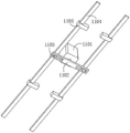
FIG. 4 is a schematic structural view of the double-linkage clamping and releasing mechanism of the present invention;
fig. 5 is a schematic structural diagram of the turnover driving mechanism of the present invention.
In the figure: 1. a support frame; 2. a turning shaft; 3. a roll-over stand; 4. a turnover driving mechanism; 401. a first motor; 402. a driving gear; 403. a driven gear; 5. a rotating shaft; 6. a rotating sheet; 7. a connecting rod; 8. a guide slider; 9. a clamping jaw; 10. a guide rail; 11. a double-linkage clamping and releasing mechanism; 1101. a second motor; 1102. a linkage plate; 1103. a pushing block; 1104. a linkage toothed plate; 1105. a guide sleeve; 1106. a linkage gear.
Detailed Description
The technical solutions in the embodiments of the present invention will be described clearly and completely with reference to the accompanying drawings in the embodiments of the present invention, and it is obvious that the described embodiments are only some embodiments of the present invention, not all embodiments. Based on the embodiments in the present invention, all other embodiments obtained by a person skilled in the art without creative efforts all belong to the protection scope of the present invention.
Referring to fig. 1-5, the present invention provides a technical solution: a frock clamp for spare and accessory part processing comprises a support frame 1, wherein the bottom of the support frame 1 is provided with a mounting hole; the whole is conveniently arranged on the processing equipment.
The top of the support frame 1 is rotatably connected with a roll-over stand 3 through a roll-over shaft 2, the side wall of the support frame 1 is also provided with a roll-over driving mechanism 4 connected with the roll-over shaft 2, the roll-over driving mechanism 4 comprises a motor I401 arranged on the side wall of the support frame 1, an output shaft of the motor I401 is fixedly connected with a driving gear 402, the driving gear 402 is meshed with a driven gear 403, and the driven gear 403 is fixedly connected at one end of the roll-over shaft 2; the parts on both sides of the roll-over stand 3 can be replaced.
A plurality of rotatable rotating shafts 5 are symmetrically arranged on two side walls of the roll-over stand 3, one end of each rotating shaft 5, which is far away from the roll-over stand 3, is fixedly connected with a rotating sheet 6, two ends of each rotating sheet 6 are respectively hinged with one end of each connecting rod 7, the other ends of the two connecting rods 7 are respectively hinged with two guide sliding blocks 8, the cross sections of the guide sliding blocks 8 are H-shaped and are arranged in guide rails 10 in a sliding manner, and one end of each guide rail 10 is fixedly connected with the side wall of the roll-over stand 3; the guide slider 8 is kept moving horizontally and is made to move more stably.
The side walls of the two guide sliding blocks 8 are fixedly connected with clamping jaws 9, the bottom of the roll-over stand 3 is fixedly provided with a double-linkage clamping and releasing mechanism 11, the double-linkage clamping and releasing mechanism 11 comprises a motor II 1101 arranged on the inner side of the roll-over stand 3, an output shaft of the motor II 1101 is fixedly connected with a linkage plate 1102, two ends of the linkage plate 1102 are respectively provided with a movable hole, a pushing block 1103 is arranged in each movable hole, the two pushing blocks 1103 are respectively and fixedly connected to the bottoms of the two linkage toothed plates 1104, the two linkage toothed plates 1104 are respectively meshed with the plurality of linkage gears 1106, and the plurality of linkage gears 1106 are respectively and fixedly connected to the plurality of rotating shafts 5; the clamping and placing actions on the workpieces can be realized, a plurality of workpieces can be processed at one time, the processing efficiency is improved, the motion states of parts on two sides of the roll-over stand 3 are just opposite, the workpieces are placed on one side, meanwhile, the workpieces are clamped on the other side, the time for taking and placing the workpieces can be saved, the machine does not need to be stopped, and the processing efficiency is further improved.
The linkage toothed plate 1104 is movably sleeved between the two guide sleeves 1105, and the two guide sleeves 1105 are fixedly connected to the side wall of the roll-over stand 3; keep the linkage toothed plate 1104 to move horizontally and make it more stable when moving.
When the double-linkage clamping and releasing mechanism is used, the whole double-linkage clamping and releasing mechanism is firstly installed on processing equipment, then a plurality of workpieces are respectively placed between a plurality of clamping jaws 9, through the arrangement of the double-linkage clamping and releasing mechanism 11, the second starting motor 1101 works and drives the linkage plate 1102 to rotate, the linkage plate 1102 drives the pushing block 1103 to move through the action of the movable hole, the pushing block 1103 drives the linkage toothed plate 1104 to move, the linkage toothed plate 1104 drives the rotating shaft 5 to rotate through the meshing action with a plurality of linkage gears 1106, the rotating shaft 5 drives the rotating sheet 6 to rotate, the rotating sheet 6 drives the guide sliding blocks 8 on two sides to move through the connecting rod 7, so that the two clamping jaws 9 are close to or far away from each other, the clamping and releasing action on the workpieces can be realized, and meanwhile, a plurality of workpieces can be processed at one time, the processing efficiency is improved, the motion states of two side parts of the turnover frame 3 are just opposite, when the processed workpieces are loosened after the workpieces on one side of the turnover frame 3 are processed, the workpieces are completely clamped on the other side, the other side of the turnover frame can be taken and the workpieces can be taken and the turnover frame can be further processed without the rotation efficiency of the turnover frame 3 being further improved.
It is noted that, herein, relational terms such as first and second, and the like may be used solely to distinguish one entity or action from another entity or action without necessarily requiring or implying any actual such relationship or order between such entities or actions. Also, the terms "comprises," "comprising," or any other variation thereof, are intended to cover a non-exclusive inclusion, such that a process, method, article, or apparatus that comprises a list of elements does not include only those elements but may include other elements not expressly listed or inherent to such process, method, article, or apparatus.
Although embodiments of the present invention have been shown and described, it will be appreciated by those skilled in the art that changes, modifications, substitutions and alterations can be made in these embodiments without departing from the principles and spirit of the invention, the scope of which is defined in the appended claims and their equivalents.
Claims (6)
1. The utility model provides a frock clamp is used in accessories processing, includes support frame (1), its characterized in that: the top of support frame (1) is rotated through trip shaft (2) and is connected with roll-over stand (3), upset actuating mechanism (4) of being connected with trip shaft (2) are still installed to the lateral wall of support frame (1), the symmetry is provided with a plurality of rotatable rotation axis (5) on the both sides wall of roll-over stand (3), the one end rigid coupling that roll-over stand (3) was kept away from in rotation axis (5) has rotor plate (6), the both ends of rotor plate (6) are articulated mutually with the one end of two connecting rods (7) respectively, the other end of two connecting rods (7) is articulated mutually with two direction slider (8) respectively, equal rigid coupling has clamping jaw (9) on the lateral wall of two direction slider (8), the bottom of roll-over stand (3) has set firmly double linkage clamping mechanism (11).
2. The tool clamp for machining the spare and accessory parts according to claim 1, characterized in that: the bottom of the support frame (1) is provided with a mounting hole.
3. The tool clamp for machining the spare and accessory parts according to claim 1, wherein: the overturning driving mechanism (4) comprises a first motor (401) arranged on the side wall of the support frame (1), a driving gear (402) is fixedly connected to an output shaft of the first motor (401), the driving gear (402) is meshed with a driven gear (403), and the driven gear (403) is fixedly connected to one end of the overturning shaft (2).
4. The tool clamp for machining the spare and accessory parts according to claim 1, characterized in that: the cross section of the guide sliding block (8) is H-shaped and is arranged in the guide rail (10) in a sliding mode, and one end of the guide rail (10) is fixedly connected with the side wall of the roll-over stand (3).
5. The tool clamp for machining the spare and accessory parts according to claim 1, characterized in that: the double-linkage clamping and placing mechanism (11) comprises a second motor (1101) arranged on the inner side of the turning frame (3), the output shaft of the second motor (1101) is fixedly connected with a linkage plate (1102), movable holes are formed in two ends of the linkage plate (1102), pushing blocks (1103) are arranged in the movable holes, the two pushing blocks (1103) are fixedly connected to the bottoms of two linkage toothed plates (1104), the two linkage toothed plates (1104) are respectively meshed with a plurality of linkage gears (1106), and the linkage gears (1106) are respectively fixedly connected to a plurality of rotating shafts (5).
6. The tool clamp for machining the spare and accessory parts according to claim 5, wherein: the linkage toothed plate (1104) is movably sleeved between the two guide sleeves (1105), and the two guide sleeves (1105) are fixedly connected to the side wall of the roll-over stand (3).
Priority Applications (1)
| Application Number | Priority Date | Filing Date | Title |
|---|---|---|---|
| CN202223186659.XU CN218556864U (en) | 2022-11-30 | 2022-11-30 | Frock clamp is used in spare and accessory part processing |
Applications Claiming Priority (1)
| Application Number | Priority Date | Filing Date | Title |
|---|---|---|---|
| CN202223186659.XU CN218556864U (en) | 2022-11-30 | 2022-11-30 | Frock clamp is used in spare and accessory part processing |
Publications (1)
| Publication Number | Publication Date |
|---|---|
| CN218556864U true CN218556864U (en) | 2023-03-03 |
Family
ID=85305636
Family Applications (1)
| Application Number | Title | Priority Date | Filing Date |
|---|---|---|---|
| CN202223186659.XU Active CN218556864U (en) | 2022-11-30 | 2022-11-30 | Frock clamp is used in spare and accessory part processing |
Country Status (1)
| Country | Link |
|---|---|
| CN (1) | CN218556864U (en) |
-
2022
- 2022-11-30 CN CN202223186659.XU patent/CN218556864U/en active Active
Similar Documents
| Publication | Publication Date | Title |
|---|---|---|
| CN218556864U (en) | Frock clamp is used in spare and accessory part processing | |
| CN217586972U (en) | Diversified detection tool | |
| CN218137916U (en) | Displacement device for large workpiece | |
| CN215846132U (en) | Firm rotation type gear machining frame | |
| CN214641449U (en) | Movable double-shaft positioner | |
| CN215469251U (en) | Fixing clamp for manufacturing mechanical equipment | |
| CN212420995U (en) | Vertical robot tool | |
| CN221564812U (en) | Main shaft clamping and feeding mechanism for vibration exciter assembly line | |
| CN221494284U (en) | Bearing retainer processingequipment | |
| CN216913057U (en) | Machine tool clamping jaw | |
| CN217913678U (en) | Mounting bracket of jig | |
| CN221935812U (en) | Steel construction installation interfacing apparatus | |
| CN217801266U (en) | Automatic locking clamp | |
| CN214518995U (en) | Automobile part tool clamp | |
| CN217254508U (en) | Automatic combination page tool clamp | |
| CN221818017U (en) | Frock clamp convenient for taking and placing workpieces for machine tool | |
| CN218363120U (en) | Welding fixing clamp for machine manufacturing | |
| CN221415559U (en) | Positioning device for automatic welding machine | |
| CN219216717U (en) | Heavy manipulator for grabbing copper foil coil of lithium battery | |
| CN220279678U (en) | Mechanical part grabbing manipulator structure | |
| CN221312577U (en) | Punching tool for machining disc parts | |
| CN218503112U (en) | Self-aligning bearing retainer punching device | |
| CN215200286U (en) | A seaming device for longitudinal welded pipe | |
| CN217529309U (en) | Drilling clamp of numerical control machine tool | |
| CN220807299U (en) | Positioning tool for machining bottom plate |
Legal Events
| Date | Code | Title | Description |
|---|---|---|---|
| GR01 | Patent grant | ||
| GR01 | Patent grant |