CN218552460U - Dental unit - Google Patents
Dental unit Download PDFInfo
- Publication number
- CN218552460U CN218552460U CN202222051670.9U CN202222051670U CN218552460U CN 218552460 U CN218552460 U CN 218552460U CN 202222051670 U CN202222051670 U CN 202222051670U CN 218552460 U CN218552460 U CN 218552460U
- Authority
- CN
- China
- Prior art keywords
- plate
- barrel
- fixedly connected
- wall
- casing
- Prior art date
- Legal status (The legal status is an assumption and is not a legal conclusion. Google has not performed a legal analysis and makes no representation as to the accuracy of the status listed.)
- Active
Links
Images


Landscapes
- Dental Tools And Instruments Or Auxiliary Dental Instruments (AREA)
Abstract
The utility model relates to a dentistry comprehensive therapy machine part, including the casing, and the top of casing is the opening setting, the top laminating of casing has the roof, be provided with first barrel in the casing, the left and right sides outer wall of first barrel is close to the equal fixedly connected with sliding plate of bottom department, and the sliding plate with the inner wall sliding connection of one side and casing that first barrel kept away from mutually, there is the second barrel through bearing swing joint in the first barrel, there is the plectane bottom of second barrel through pivot and bearing swing joint, mutually supporting between parts such as electric telescopic handle, promotion piece, kicking block and open-close board in this technical scheme, can realize carrying out effectual fixed to article and part, can effectually prevent droing of article and instrument, can realize shifting out the case or move into the casing through setting up of electric jar, reach the convenient mesh of taking and depositing, can realize carrying out effectual protection to article and instrument simultaneously.
Description
Technical Field
The utility model relates to a comprehensive treatment machine part, in particular to a dental comprehensive treatment machine part.
Background
One of the dental medical disciplines is generally incorporated in the department of stomatology in hospitals, dentistry mainly treats diseases related to teeth and periodontal, and the comprehensive therapy machine part is one of the devices commonly used in dentistry, and the article and tool storage device is one of the important components of the dental comprehensive therapy machine part, but the dental comprehensive therapy machine part in the prior art cannot effectively fix articles and tools and cannot effectively protect the articles and tools when in use, so that a dental comprehensive therapy machine part is provided.
SUMMERY OF THE UTILITY MODEL
Aiming at the defects of the prior art, the utility model provides a dental comprehensive treatment machine component, which overcomes the defects of the prior art.
In order to solve the technical problem, the utility model provides a following technical scheme: a dental comprehensive treatment machine component comprises a shell, wherein the top of the shell is provided with an opening, a top plate is attached to the top of the shell, a first barrel is arranged in the shell, sliding plates are fixedly connected to the outer walls of the left side and the right side of the first barrel, which are close to the bottom, of the first barrel, the sliding plates are slidably connected with the inner wall of the shell, a second barrel is movably connected in the first barrel through bearings, circular plates are movably connected to the bottom of the second barrel through rotating shafts and bearings, the circular plates are installed on the inner wall of the first barrel, a servo motor is installed on the bottom of each circular plate, the bottom end of each rotating shaft on the bottom of the second barrel penetrates through the inner ring of each bearing and is fixedly connected with the output shaft of the servo motor, a vertical rod is fixedly connected between the bottom of the top plate and the top of each sliding plate, four fixing blocks are uniformly installed on the outer wall of the second barrel, which is close to the top, a storage box is installed on the top of each fixing block, the top of the storage box is provided with the opening plate, an opening plate is arranged in the storage box, the side wall of the opening plate is movably connected with the inner wall of the storage box through the rotating shafts and the bottom of the opening plate, torsion spring, two ends of the storage box are respectively connected with the inner walls of the opening plate, and the fixing plates, and the opening plate are connected with the fixing plates, and the opening plates, and the outer walls of the storage box, and the opening plates are respectively connected with the opening plates;
sliding connection has L shape layer board on the left side inner wall of casing, first slider is installed in the left side of L shape layer board, just set up on the left side inner wall of casing with first slider assorted first spout, the right side fixedly connected with electric telescopic handle of L shape layer board, electric telescopic handle's right-hand member fixedly connected with and kicking block assorted promote the piece, fixedly connected with electric jar on the inner chamber bottom of casing, and the bottom plate fixed connection of the push rod top on the electric jar and first barrel, fixedly connected with buffer spring between the bottom of sliding plate and the inner chamber bottom of casing.
As a preferred technical scheme of the utility model, the left side outer wall of first barrel is close to top department and installs the straight board, the cylinder is installed at the top of straight board, the bottom fixed connection of push rod top and the L shape layer board on the cylinder top.
As a preferred technical scheme of the utility model, install the air heater on the inner chamber bottom of second barrel, and the top of air heater goes out the tuber pipe and is corresponding with the open-top of second barrel.
As a preferred technical scheme of the utility model, install the pipe on the top of roof, and the both sides of pipe set up for sealing, install the trachea that gathers in the pipe, the air exhauster is installed at the top of pipe, the intake pipe of air exhauster is linked together with the inside of gathering the trachea and is connected, the left and right sides that gathers the trachea all communicates and is connected with the air duct, and the bottom of air duct runs through the inside of roof and casing and is linked together.
As an optimal technical scheme of the utility model, the spacing groove has all been seted up on the antetheca of case and the back wall, and all installs two gag lever posts on the antetheca of opening plate and the back wall.
As an optimal technical scheme of the utility model, the second slider is installed to one side that the sliding plate kept away from with first barrel mutually, just seted up on the inner wall of casing with second slider assorted second spout.
As a preferred technical scheme of the utility model, the bottom fixedly connected with supporting baseplate of casing, the screw hole has all been seted up near four corners department at supporting baseplate's top.
The embodiment of the utility model provides a dental unit part possesses following beneficial effect:
1. in the technical scheme, the electric telescopic rod, the pushing block, the jacking block, the opening plate and other parts are matched with each other, so that the objects and the parts can be effectively fixed, and the objects and tools can be effectively prevented from falling off;
2. can realize shifting out the case or moving into the casing through the setting of electric jar among this technical scheme, reach the purpose of convenient taking and depositing, can realize carrying out effectual protection to article and instrument simultaneously.
Drawings
The accompanying drawings are included to provide a further understanding of the invention, and are incorporated in and constitute a part of this specification, illustrate embodiments of the invention, and together with the description serve to explain the invention and not to limit the invention. In the drawings:
FIG. 1 is a schematic view of the overall structure of the present invention;
FIG. 2 is a schematic cross-sectional view of the structure of FIG. 1;
FIG. 3 is a partial plan view of the second cylinder, the storage box, etc.;
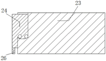
FIG. 4 is a partial front view of the storage box;
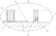
fig. 5 is an enlarged view at a in fig. 2.
In the figure: 1. a housing; 2. a support base plate; 3. a top plate; 4. a circular tube; 5. an exhaust fan; 6. an air duct; 7. a second cylinder; 8. a straight plate; 9. a cylinder; 10. a first cylinder; 11. an electric cylinder; 12. a servo motor; 13. a circular plate; 14. a sliding plate; 15. a buffer spring; 16. a vertical rod; 17. an L-shaped support plate; 18. an electric telescopic rod; 19. a gas collecting pipe; 20. a fixed block; 21. a torsion spring; 22. a hot air blower; 23. a storage box; 24. opening and closing the plate; 25. a pushing block; 26. and (7) a top block.
Detailed Description
The preferred embodiments of the present invention will be described in conjunction with the accompanying drawings, and it will be understood that they are presented herein only to illustrate and explain the present invention, and not to limit the present invention.
Example (b): as shown in figures 1-5, a dental unit comprises a housing 1, wherein the top of the housing 1 is provided with an opening, the top of the housing 1 is attached with a top plate 3, the bottom of the housing 1 is fixedly connected with a supporting bottom plate 2, the top of the supporting bottom plate 2 near four corners is provided with screw holes, the housing 1 is internally provided with a first cylinder 10, the outer walls of the left and right sides of the first cylinder 10 near the bottom are fixedly connected with sliding plates 14, the side of the sliding plate 14 far away from the first cylinder 10 is provided with a second sliding block, the inner wall of the housing 1 is provided with a second sliding groove matched with the second sliding block, the side of the sliding plate 14 far away from the first cylinder 10 is connected with the inner wall of the housing 1 in a sliding manner, the first cylinder 10 is movably connected with a second cylinder 7 through a bearing, the bottom of the second cylinder 7 is movably connected with a circular plate 13 through a rotating shaft and a bearing, a circular plate 13 is arranged on the inner wall of the first cylinder 10, a servo motor 12 is arranged on the bottom of the circular plate 13, the bottom end of a rotating shaft on the bottom of the second cylinder 7 penetrates through an inner ring of a bearing and is fixedly connected with an output shaft of the servo motor 12, a vertical rod 16 is fixedly connected between the bottom of the top plate 3 and the top of the sliding plate 14, four fixing blocks 20 are uniformly arranged on the outer wall of the second cylinder 7 close to the top, a storage box 23 is arranged on the top of each fixing block 20, an opening plate 24 is arranged in the storage box 23, the side wall of the opening plate 24 close to the bottom is movably connected with the inner wall of the storage box 23 through a rotating shaft and the bearing, a spring 21 is sleeved on the rotating shaft of the opening plate 24, two ends of a torsion force of the torsion spring 21 are respectively and fixedly connected with the inner walls of the opening plate 24 and the storage box 23, the opening plate 24 extends out of the storage box 23, and the bottom of the opening plate 24 is fixedly connected with a top block 26, the front wall and the rear wall of the storage box 23 are both provided with a limiting groove, and the front wall and the rear wall of the opening plate 24 are both provided with two limiting rods;
the inner wall of the left side of the shell 1 is connected with an L-shaped supporting plate 17 in a sliding mode, a first sliding block is installed on the left side of the L-shaped supporting plate 17, a first sliding groove matched with the first sliding block is formed in the inner wall of the left side of the shell 1, an electric telescopic rod 18 is fixedly connected to the right side of the L-shaped supporting plate 17, a pushing block 25 matched with a jacking block 26 is fixedly connected to the right end of the electric telescopic rod 18, an electric cylinder 11 is fixedly connected to the bottom of an inner cavity of the shell 1, the top end of a push rod on the electric cylinder 11 is fixedly connected with a bottom plate of the first cylinder 10, a buffer spring 15 is fixedly connected between the bottom of the sliding plate 14 and the bottom of the inner cavity of the shell 1, the storage box 23 can be moved out of or into the shell 1 through the arrangement of the electric cylinder 11, the purposes of convenient taking and storage are achieved, and meanwhile effective protection on articles and tools can be achieved;
in the embodiment, through the mutual matching among the parts such as the electric telescopic rod 18, the pushing block 25, the jacking block 26, the opening plate 24 and the like, the objects and the parts can be effectively fixed, and the objects and tools can be effectively prevented from falling off;
a straight plate 8 is arranged on the outer wall of the left side of the first cylinder 10 close to the top, an air cylinder 9 is arranged on the top of the straight plate 8, and the top end of a push rod on the top of the air cylinder 9 is fixedly connected with the bottom of the L-shaped supporting plate 17;
in the embodiment, the upper and lower positions of the L-shaped supporting plate 17 and the pushing block 25 can be adjusted, so that the L-shaped supporting plate and the pushing block can be matched with the position of the top block 26;
the air heater 22 is installed at the bottom of the inner cavity of the second barrel 7, an air outlet pipe at the top of the air heater 22 corresponds to an opening at the top of the second barrel 7, the round pipe 4 is installed at the top of the top plate 3, two sides of the round pipe 4 are arranged in a closed mode, the air collecting pipe 19 is installed in the round pipe 4, the exhaust fan 5 is installed at the top of the round pipe 4, an air inlet pipe of the exhaust fan 5 is communicated and connected with the inside of the air collecting pipe 19, the air guide pipes 6 are communicated and connected with the left side and the right side of the air collecting pipe 19, and the bottom end of each air guide pipe 6 penetrates through the top plate 3 and is communicated with the inside of the shell 1;
in this embodiment, can realize disinfecting the article in casing 1, can effectual improvement its availability factor.
The working principle is as follows: when the technical scheme is used, firstly, the electric cylinder 11 is started, a push rod of the electric cylinder 11 extends upwards and drives the second cylinder 7 and the storage box 23 to move upwards through the first cylinder 10, meanwhile, the first cylinder 10 drives the sliding plate 14 to move upwards so that the vertical rod 16 drives the top plate 3 to move upwards, when the storage box 23 and the like move out of the shell 1, the electric cylinder 11 is closed, the air cylinder 9 is started, the push rod on the air cylinder 9 contracts or extends to drive the L-shaped supporting plate 17 to move downwards or upwards, the upper and lower positions of the L-shaped supporting plate 17 and the pushing block 25 can be adjusted to be matched with the position of the top block 26, the electric telescopic rod 18 is started to extend outwards and drive the pushing block 25 to move rightwards and abut against the top block 26, the top block 26 drives the opening plate 24 to open outwards, articles and tools are placed in the storage box 23, the electric telescopic rod 18 is started, the electric telescopic rod 18 contracts so that the pushing block 25 is separated from the top block 26, at this time, under the elastic force of the torsion spring 21, the open-close plate 24 is restored to the original position and the articles and tools are clamped, then the servo motor 12 is started, the servo motor 12 drives the second cylinder 7 to rotate, the other three storage boxes 23 are sequentially arranged on the front side, and the operations are repeated to sequentially arrange the articles and tools in the four storage boxes 23, so that the articles and the parts can be effectively fixed, the articles and the tools can be effectively prevented from falling off, then the electric cylinder 11 is started, the push rod of the electric cylinder 11 is contracted downwards and drives the second cylinder 7 and the storage boxes 23 to move downwards through the first cylinder 10, meanwhile, the first cylinder 10 drives the sliding plate 14 to move downwards so that the vertical rod 16 drives the top plate 3 to move downwards, when the storage boxes 23 move into the equal-sized shell 1, the electric cylinder 11 is closed, the storage boxes 23 can be moved out of or into the shell 1, and the purposes of convenient taking and storage can be achieved, can realize carrying out effectual protection to article and instrument simultaneously, start air heater 22, air heater 22 spouts steam to carry out high temperature disinfection to article and instrument, start air exhauster 5 after the disinfection is accomplished the cooling, air exhauster 5 passes through air duct 6, gathers the trachea 19 and takes out, can realize driving the circulation of air of casing 1, can keep the drying of article and instrument.
Finally, it should be noted that: in the description of the present invention, it should be noted that the terms "vertical", "upper", "lower", "horizontal", and the like indicate orientations or positional relationships based on the orientations or positional relationships shown in the drawings, and are only for convenience of description and simplification of description, but do not indicate or imply that the device or element referred to must have a specific orientation, be constructed in a specific orientation, and be operated, and thus should not be construed as limiting the present invention.
In the description of the present invention, it should also be noted that, unless otherwise explicitly specified or limited, the terms "disposed," "mounted," "connected," and "connected" are to be construed broadly, e.g., as meaning either a fixed connection, a removable connection, or an integral connection; can be mechanically or electrically connected; they may be connected directly or indirectly through intervening media, or they may be interconnected between two elements. The specific meaning of the above terms in the present invention can be understood according to specific situations by those skilled in the art.
Although the present invention has been described in detail with reference to the foregoing embodiments, it will be apparent to those skilled in the art that modifications may be made to the embodiments described in the foregoing embodiments, or equivalents may be substituted for elements thereof. Any modification, equivalent replacement, or improvement made within the spirit and principle of the present invention should be included in the protection scope of the present invention.
Claims (7)
1. The dental comprehensive therapy apparatus component comprises a shell (1), wherein the top of the shell (1) is provided with an opening, a top plate (3) is attached to the top of the shell (1), and is characterized in that a first barrel (10) is arranged in the shell (1), outer walls of the left side and the right side of the first barrel (10) are fixedly connected with a sliding plate (14) close to the bottom, one side, away from the sliding plate (14) and the first barrel (10), of the sliding plate is connected with the inner wall of the shell (1) in a sliding manner, a second barrel (7) is movably connected in the first barrel (10) through a bearing, the bottom of the second barrel (7) is fixedly connected with a circular plate (13) through a rotating shaft and a bearing, the circular plate (13) is installed on the inner wall of the first barrel (10), a servo motor (12) is installed on the bottom of the circular plate (13), the bottom end of the rotating shaft on the bottom of the second barrel (7) penetrates through the inner ring of the bearing and is fixedly connected with an output shaft of the servo motor (12), a vertical rod (16) is fixedly connected between the bottom of the top plate (3) and the top of the sliding plate (14), storage box (23) is installed on the outer wall of the second barrel (7), four storage boxes (23) close to the top of the storage box (23), the storage box (23) are provided with an opening, the storage box (23), the side wall of the opening plate (24) is movably connected with the inner wall of the storage box (23) through a rotating shaft and a bearing close to the bottom, the rotating shaft on the opening plate (24) is sleeved with a torsion spring (21), two ends of the torsion spring (21) are fixedly connected with the inner walls of the opening plate (24) and the storage box (23) respectively, the opening plate (24) extends out of the storage box (23), and the bottom of the opening plate (24) is fixedly connected with a top block (26);
sliding connection has L shape layer board (17) on the left side inner wall of casing (1), first slider is installed in the left side of L shape layer board (17), just set up on the left side inner wall of casing (1) with first slider assorted first spout, the right side fixedly connected with electric telescopic handle (18) of L shape layer board (17), the right-hand member fixedly connected with and the kicking block (26) assorted of electric telescopic handle (18) promote piece (25), fixedly connected with electric jar (11) on the inner chamber bottom of casing (1), and the bottom plate fixed connection of the push rod top on electric jar (11) and first barrel (10), fixedly connected with buffer spring (15) between the bottom of sliding plate (14) and the inner chamber bottom of casing (1).
2. A dental unit according to claim 1, wherein a straight plate (8) is mounted on the left outer wall of the first cylinder (10) near the top, a cylinder (9) is mounted on the top of the straight plate (8), and the top end of a push rod on the top of the cylinder (9) is fixedly connected with the bottom of the L-shaped supporting plate (17).
3. Dental unit according to claim 1, wherein the bottom of the inner cavity of the second cylinder (7) is provided with a hot air blower (22), and the top outlet duct of the hot air blower (22) corresponds to the top opening of the second cylinder (7).
4. The dental unit according to claim 1, wherein a round tube (4) is installed on the top of the top plate (3), the two sides of the round tube (4) are arranged in a closed manner, a gas gathering tube (19) is installed in the round tube (4), an exhaust fan (5) is installed on the top of the round tube (4), the gas inlet tube of the exhaust fan (5) is communicated with the inside of the gas gathering tube (19), the left side and the right side of the gas gathering tube (19) are both communicated and connected with the gas guide tube (6), and the bottom end of the gas guide tube (6) penetrates through the top plate (3) and is communicated with the inside of the shell (1).
5. The dental unit component according to claim 1, wherein the front wall and the rear wall of the storage box (23) are provided with limiting grooves, and the front wall and the rear wall of the opening plate (24) are provided with two limiting rods.
6. A dental unit according to claim 1, wherein a second slider is mounted on the side of the sliding plate (14) remote from the first cylinder (10), and a second sliding slot matching with the second slider is formed on the inner wall of the housing (1).
7. The dental unit according to claim 1, wherein a bottom plate (2) is fixedly connected to the bottom of the housing (1), and screw holes are formed in the top of the bottom plate (2) near four corners.
Priority Applications (1)
| Application Number | Priority Date | Filing Date | Title |
|---|---|---|---|
| CN202222051670.9U CN218552460U (en) | 2022-08-05 | 2022-08-05 | Dental unit |
Applications Claiming Priority (1)
| Application Number | Priority Date | Filing Date | Title |
|---|---|---|---|
| CN202222051670.9U CN218552460U (en) | 2022-08-05 | 2022-08-05 | Dental unit |
Publications (1)
| Publication Number | Publication Date |
|---|---|
| CN218552460U true CN218552460U (en) | 2023-03-03 |
Family
ID=85307194
Family Applications (1)
| Application Number | Title | Priority Date | Filing Date |
|---|---|---|---|
| CN202222051670.9U Active CN218552460U (en) | 2022-08-05 | 2022-08-05 | Dental unit |
Country Status (1)
| Country | Link |
|---|---|
| CN (1) | CN218552460U (en) |
-
2022
- 2022-08-05 CN CN202222051670.9U patent/CN218552460U/en active Active
Similar Documents
| Publication | Publication Date | Title |
|---|---|---|
| CN211060395U (en) | Novel electric hot air circulating furnace | |
| CN218552460U (en) | Dental unit | |
| CN109405474A (en) | A kind of high-efficiency vacuum drying box | |
| CN111802816A (en) | Energy-saving dust removal wardrobe capable of efficiently collecting dust | |
| CN110102885A (en) | A kind of laser cutting machine recycled completely with absorption raw material and exhaust gas | |
| CN113304289A (en) | Surgical instrument disinfection and sterilization equipment based on field conditions | |
| CN218174941U (en) | Microbial limit detector for loratadine preparation | |
| CN217847007U (en) | Computer is ash removal device for quick-witted case | |
| CN207369655U (en) | A kind of municipal administration gardens vegetation clipping device | |
| CN213552344U (en) | Medical instrument storing compartment | |
| CN219743236U (en) | Remains bone ash absorbing equipment | |
| CN219112464U (en) | Biological safety fume chamber | |
| CN216116159U (en) | Device for evaluating atmospheric environment influence | |
| CN117064421B (en) | Radiology department abdomen image display device | |
| CN110806083A (en) | Drying device for food processing | |
| CN218936897U (en) | High-efficient drying cabinet of tomato pollen | |
| CN212631241U (en) | Internal medicine nursing apparatus degassing unit | |
| CN218376980U (en) | Cabinet type fan box | |
| CN219901559U (en) | Internal grinding machine for dental model | |
| CN214426323U (en) | Device for air drying and disinfecting pathological slide | |
| CN216908694U (en) | Portable kitchen sterilizer convenient to take | |
| CN219358967U (en) | Valve production is with equipment of polishing | |
| CN216180308U (en) | Model making devices for architectural design | |
| CN213818497U (en) | Medical data processing device based on block chain technology | |
| CN220507501U (en) | Drying device for ceramic processing |
Legal Events
| Date | Code | Title | Description |
|---|---|---|---|
| GR01 | Patent grant | ||
| GR01 | Patent grant |