CN218544359U - LED bulb lamp heat radiation structure - Google Patents
LED bulb lamp heat radiation structure Download PDFInfo
- Publication number
- CN218544359U CN218544359U CN202223008924.5U CN202223008924U CN218544359U CN 218544359 U CN218544359 U CN 218544359U CN 202223008924 U CN202223008924 U CN 202223008924U CN 218544359 U CN218544359 U CN 218544359U
- Authority
- CN
- China
- Prior art keywords
- heat dissipation
- lamp
- chamber
- power
- led bulb
- Prior art date
- Legal status (The legal status is an assumption and is not a legal conclusion. Google has not performed a legal analysis and makes no representation as to the accuracy of the status listed.)
- Active
Links
Images


Landscapes
- Arrangement Of Elements, Cooling, Sealing, Or The Like Of Lighting Devices (AREA)
Abstract
The utility model discloses a LED ball bubble lamp heat radiation structure body, including lamp shade, lamp plate, power, base and heat dissipation main part, the heat dissipation main part is including depositing the power chamber, the heat dissipation chamber and the backup pad of power, the pedestal mounting in the one end of power chamber, a side in heat dissipation chamber does the outer wall in power chamber, the external surface fixation of heat dissipation chamber another side the lamp plate, the heat dissipation chamber is equipped with an air intake, the edge connection of air intake the backup pad, the lamp shade is fixed in the backup pad. The utility model discloses have high radiating rate, high illuminating effect, low cost, easy installation, high protection level and support the advantage of high-power output.
Description
Technical Field
The utility model relates to a LED illumination field particularly, relates to a LED ball bubble lamp heat radiation structure.
Background
Along with the high-speed development of the LED illumination technology, the LED bulb lamp is deeply popular with small size and high energy-saving effect, and the LED bulb lamp on the market at present has the following limitations:
the first limitation is that the lamp panel is generally directly contacted with the heat sink in heat dissipation, the heat sink transfers heat to the outside through a plurality of heat dissipation fins vertically contacted with the heat sink, the heat dissipation time of the heat sink is prolonged due to the need of secondary heat dissipation of the heat dissipation fins, so that the temperature on the heat sink is too high, the material cost and the installation time of the LED bulb lamp are increased due to the combination of the heat sink and the heat dissipation fins, and meanwhile, the heat dissipation fins occupy most of the volume of the bulb lamp, so that the LED bulb lamp cannot be provided with larger or more PCB boards, the number of light sources is limited, and the illumination effect is poor.
And secondly, on the basis of the first limitation, in order to prevent heat brought by the power supply from influencing the heat dissipation of the LED bulb lamp, the power supply is generally small in size and is fixed on the base far away from one end of the lamp panel, the cost is further increased by the small-size power supply, and meanwhile, the output power of the power supply is limited, and the power of the LED bulb lamp cannot be increased.
SUMMERY OF THE UTILITY MODEL
In order to solve the technical problem, the utility model provides a LED ball bubble lamp heat radiation structure can install more LED light sources when improving the radiating effect, improves the illuminating effect, and is low to the power volume requirement degree of LED ball bubble lamp simultaneously, can install more powerful power, and then improves the power of LED ball bubble lamp.
The utility model discloses an adopt following mode to realize: the utility model provides a LED ball bubble lamp heat radiation structure, includes lamp shade, lamp plate, power, base and heat dissipation main part, the heat dissipation main part is including depositing the power chamber, the heat dissipation chamber and the backup pad of power, the pedestal mounting in the one end in power chamber, a side in heat dissipation chamber does the outer wall in power chamber, the external surface fixation of heat dissipation chamber another side the lamp plate, the heat dissipation chamber is equipped with an air intake, the edge connection of air intake the backup pad, the lamp shade is fixed in the backup pad.
Preferably, the heat dissipation cavity is fixed the surface of lamp plate with power supply cavity outer wall is the contained angle setting.
Preferably, the heat dissipation cavity is fixed the surface of lamp plate with power supply cavity outer wall parallel arrangement.
Preferably, the number of the heat dissipation cavities is more than 2.
Preferably, the heat dissipation cavities are arranged on the outer wall of the power supply cavity in a surrounding mode at intervals.
Preferably, the heat dissipation body is integrally formed in a mold.
Preferably, the outer edge of the supporting plate is clamped with the lampshade.
Preferably, the clamping position of the outer edge of the supporting plate and the lampshade is glued.
Preferably, the lampshade is a transparent cover or a frosted cover.
Because of the application of above technical scheme, the utility model discloses beneficial effect who compares with prior art is: by arranging the heat dissipation cavity, heat on the lamp panel can directly contact external air through the heat dissipation cavity, so that the temperature is rapidly reduced, the heat dissipation efficiency is improved, the heat dissipation between a light source and a power supply of the LED bulb lamp is not interfered by the heat dissipation cavity, the temperature of the whole lamp is further reduced, the service life of the LED bulb lamp is prolonged, heat dissipation fins are not needed, and the material cost is reduced; the outer surfaces of the plurality of heat dissipation cavities surrounding the outer wall of the power supply cavity can bear more lamp panels, so that more LED light sources are mounted, and the lighting effect is improved; by arranging the independent power supply cavity, a power supply with larger volume and larger power can be accommodated, so that the power of the LED bulb lamp is improved; the lamp shade is connected with the supporting plate of the heat dissipation main body in a clamping and gluing mode, so that the sealing performance of the LED bulb lamp is enhanced; the heat dissipation main part is integrated into one piece in the mould, has reduced the spare part of whole lamp for whole lamp is installed easily.
To sum up, the utility model discloses have high heat dissipation rate, high illuminating effect, low cost, easy installation, high protection level and support the advantage of high-power output.
Drawings
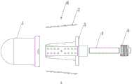
Fig. 1 is an exploded view of a heat dissipation structure of an LED bulb according to an embodiment of the present invention.
Fig. 2 is a vertical sectional view of the heat dissipation structure of the LED bulb lamp passing through the heat dissipation chamber in the embodiment of the present invention.
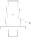
Fig. 3 is a front view of a heat dissipation main body of a heat dissipation structure of an LED bulb.
Fig. 4 is a top view of a heat dissipation main body of a heat dissipation structure of an LED bulb.
Fig. 5 is a bottom view of the heat dissipating body of the heat dissipating structure of the LED bulb.
Fig. 6 is a vertical sectional view of the heat dissipation structure of the LED bulb lamp passing through the heat dissipation chamber in the embodiment of the present invention.
Reference numerals: the lamp comprises a transparent lampshade 1, a lamp panel 2, a heat dissipation main body 3, a power supply cavity 31, a heat dissipation cavity 32, a support plate 33, a power supply 4, a base 5 and screws 6.
Detailed Description
The invention will be further elucidated with reference to the drawings and the embodiments, which are exemplary only and do not limit the scope of the invention.
In the description of the present invention, it should be noted that the terms "top", "bottom", "one side", "the other side", "inside", "outside", "up", "middle", "under", "down", "middle", and the like indicate orientations or positional relationships based on the orientations or positional relationships shown in the drawings, and are only for convenience of description and simplification of the description, but do not indicate or imply that the device or element referred to must have a specific orientation, be constructed and operated in a specific orientation, and thus, should not be construed as limiting the present invention;
please refer to fig. 1-6, the utility model provides a heat radiation structure of LED bulb lamp, including transparent lamp shade 1, lamp plate 2, power 4, base 5 and heat dissipation main part 3, heat dissipation main part 3 is including depositing power chamber 31, heat dissipation chamber 32 and backup pad 33 of power 4, base 5 install in the bottom of power chamber 31, a side in heat dissipation chamber 32 does the outer wall of power chamber 31, the surface mounting of heat dissipation chamber 32 another side the lamp plate 2, the bottom in heat dissipation chamber 32 is equipped with an air intake, the edge connection of air intake backup pad 33, transparent lamp shade 1 is fixed on backup pad 33.
The heat dissipation chamber 32 is fixed the surface of lamp plate 2 with power cavity 31 outer wall is certain contained angle slope setting, the space width of the top to the bottom in heat dissipation chamber 32 progressively enlarges.
The heat dissipation chamber 32 has 4, 4 heat dissipation chambers 32 evenly encircle set up in the outer wall of power supply chamber 31, power supply chamber 31 is cylindricly, 4 square quadrangular prism big end down are constituteed to the surface in heat dissipation chamber 32, consequently 4 can be installed altogether to the surface in 4 heat dissipation chambers 32 lamp plate 2, can install more LED light sources, improve illuminating effect.
The power supply cavity 31 is located in the middle of the heat dissipation body 3, the supporting plate 33 is located below the heat dissipation cavity 32 and located below the heat dissipation body 3, and the bottom of the power supply cavity 31 protrudes out of the lower surface of the supporting plate 33 and is used for fixing the base 5.
Screw holes are formed in the middle between the heat dissipation cavities 32 and are used for fixing the lamp panel 2 on the outer surface of the heat dissipation cavities 32 through the screws 6; the top of the power supply cavity 31 is provided with a wire passing hole for the power supply 4 to supply power to the lamp panel 2.
The heat dissipation body 3 is integrally formed in a mold by a mold pressing method.
The utility model discloses a set up 4 heat dissipation chamber 32, the heat on lamp plate 2 can pass through heat dissipation chamber 32 direct contact outside air, cool down rapidly, improve the radiating efficiency, and heat dissipation chamber 32 still makes the heat dissipation between lamp plate 2 and the power 4 noninterference, further reduces the temperature of whole lamp, improves the life of LED ball bubble lamp, and need not to use heat radiation fins, reduces material cost; the outer surfaces of the plurality of heat dissipation cavities 32 surrounding the outer wall of the power supply cavity 31 can bear more lamp panels 2, so that more LED light sources are installed, and the lighting effect is improved; by arranging the independent power supply cavity 31, the power supply 4 with larger volume and larger power can be accommodated, so that the power of the LED bulb lamp is improved; the transparent lampshade 1 and the supporting plate 33 of the heat dissipation main body 3 are connected in a clamping and gluing mode, so that the sealing performance of the LED bulb lamp is enhanced; the heat dissipation main body 3 is integrally formed in the die, so that the number of parts of the whole lamp is reduced, and the whole lamp is easy to install.
The above embodiments do not limit the scope of the present invention, and those skilled in the art can make equivalent modifications and variations without departing from the overall concept of the present invention.
Claims (9)
1. The utility model provides a LED ball bubble lamp heat radiation structure, its characterized in that, includes lamp shade, lamp plate, power, base and heat dissipation main part, the heat dissipation main part is including depositing the power chamber, the heat dissipation chamber and the backup pad of power, the pedestal mounting in the one end in power chamber, a side in heat dissipation chamber does the outer wall in power chamber, the external surface of heat dissipation chamber another side is fixed the lamp plate, the heat dissipation chamber is equipped with an air intake, the edge connection of air intake the backup pad, the lamp shade is fixed in the backup pad.
2. The LED bulb lamp heat dissipation structure as recited in claim 1, wherein the heat dissipation cavity fixes an outer surface of the lamp panel and forms an included angle with an outer wall of the power supply cavity.
3. The LED bulb lamp heat dissipation structure as recited in claim 1, wherein the heat dissipation cavity fixes the outer surface of the lamp panel and is parallel to the outer wall of the power supply cavity.
4. The LED bulb lamp heat dissipation structure of claim 1, wherein the number of the heat dissipation cavities is more than 2.
5. The LED bulb lamp heat dissipation structure of claim 4, wherein the heat dissipation cavities are spaced around the outer wall of the power supply cavity.
6. The LED bulb lamp heat dissipation structure as recited in claim 1, wherein the heat dissipation body is integrally formed in a mold.
7. The LED bulb lamp heat dissipation structure of claim 1, wherein an outer edge of the support plate is snap-fitted to the lamp cover.
8. The LED bulb lamp heat dissipation structure body of claim 7, wherein a clamping connection between the outer edge of the support plate and the lamp shade is glued.
9. The LED bulb lamp heat dissipation structure of claim 1, wherein the lamp shade is a transparent shade or a frosted shade.
Priority Applications (1)
| Application Number | Priority Date | Filing Date | Title |
|---|---|---|---|
| CN202223008924.5U CN218544359U (en) | 2022-11-11 | 2022-11-11 | LED bulb lamp heat radiation structure |
Applications Claiming Priority (1)
| Application Number | Priority Date | Filing Date | Title |
|---|---|---|---|
| CN202223008924.5U CN218544359U (en) | 2022-11-11 | 2022-11-11 | LED bulb lamp heat radiation structure |
Publications (1)
| Publication Number | Publication Date |
|---|---|
| CN218544359U true CN218544359U (en) | 2023-02-28 |
Family
ID=85260031
Family Applications (1)
| Application Number | Title | Priority Date | Filing Date |
|---|---|---|---|
| CN202223008924.5U Active CN218544359U (en) | 2022-11-11 | 2022-11-11 | LED bulb lamp heat radiation structure |
Country Status (1)
| Country | Link |
|---|---|
| CN (1) | CN218544359U (en) |
-
2022
- 2022-11-11 CN CN202223008924.5U patent/CN218544359U/en active Active
Similar Documents
| Publication | Publication Date | Title |
|---|---|---|
| KR20090013011A (en) | High-power light emitting diode(led) street lamp and body frame thereof | |
| KR20090006720A (en) | High-power light emitting diode(led) street lamp and body frame thereof | |
| CN201521826U (en) | LED explosion-proof floodlight | |
| CN201096295Y (en) | Ceiling type LED barrel lamp | |
| CN218544359U (en) | LED bulb lamp heat radiation structure | |
| CN202048469U (en) | Light-emitting diode (LED) tube light | |
| CN201897160U (en) | Light emitting diode lamp | |
| CN211475654U (en) | Screw-free structure direct type panel lamp | |
| CN212902213U (en) | Refrigerator and refrigerator lamp with double-side light emitting | |
| CN209213576U (en) | A kind of LED wall lamp | |
| CN203147522U (en) | Embedded-type LED illuminating lamp | |
| CN202001863U (en) | Integrally encapsulated LED light source with high heat radiation performance | |
| CN110671653A (en) | Lens combined lamp | |
| CN220707110U (en) | Layered down lamp structure | |
| CN215001237U (en) | Grille projection lamp | |
| CN219756180U (en) | Embedded LED lighting lamp | |
| CN217503442U (en) | High-efficient radiating profection lamp | |
| CN215001038U (en) | Novel can dismantle LED lamp | |
| CN210424647U (en) | LED projection lamp with simple structure | |
| CN218154117U (en) | High-efficient radiating led lamp plate | |
| CN212777013U (en) | Novel LED illuminating lamp | |
| CN214948913U (en) | High-efficient radiating combination formula LED grille shot-light | |
| CN216431452U (en) | LED heat dissipation down lamp | |
| CN218583041U (en) | General type LED module of lighting device | |
| CN219775647U (en) | Lamp shell structure |
Legal Events
| Date | Code | Title | Description |
|---|---|---|---|
| GR01 | Patent grant | ||
| GR01 | Patent grant |