CN218523981U - Forced multi-wing fan blade heat exchanger - Google Patents
Forced multi-wing fan blade heat exchanger Download PDFInfo
- Publication number
- CN218523981U CN218523981U CN202222741077.7U CN202222741077U CN218523981U CN 218523981 U CN218523981 U CN 218523981U CN 202222741077 U CN202222741077 U CN 202222741077U CN 218523981 U CN218523981 U CN 218523981U
- Authority
- CN
- China
- Prior art keywords
- heat exchanger
- fan blade
- motor
- wing fan
- exchanger body
- Prior art date
- Legal status (The legal status is an assumption and is not a legal conclusion. Google has not performed a legal analysis and makes no representation as to the accuracy of the status listed.)
- Active
Links
Images


Abstract
The utility model discloses a force multi-wing fan blade heat exchanger, including the heat exchanger body, pneumatic motor or electric motor are installed at the top of heat exchanger body, one side of motor is connected with the wind wing fan blade, the internally mounted of heat exchanger body has the wind wing fan blade, the outside of wind wing fan blade is equipped with the fin heat exchange tube, one side of heat exchanger body is connected with the drain pipe, the opposite side of heat exchanger body is connected with the feed liquor pipe. The heat exchanger adopts a bidirectional multi-wing centrifugal wind blade structure, has the advantages of large wind volume, high wind pressure, high efficiency and the like, and improves the conventional natural wind cooling effect; the electric motor is replaced by the motor, so that the explosion-proof problem of the device is solved, energy is saved, and the device is environment-friendly, safe and reliable; the problem that the traditional cooling water is used for cooling to cause equipment scaling so as to influence the use effect is solved, the situation that the device is on site without cooling water is solved, and energy conservation and emission reduction are realized.
Description
Technical Field
The utility model relates to a heat exchanger field specifically is a force multi-wing fan blade heat exchanger.
Background
Heat exchangers (also known as heat exchangers or heat exchange devices) are devices used to transfer heat from a hot fluid to a cold fluid to meet specified process requirements, and are an industrial application of convective and conductive heat transfer. Heat exchangers can be classified in different ways. The operation process can be divided into three categories of dividing wall type, mixed type and heat accumulating type (or called regenerative type); the degree of compactness of the surface thereof can be classified into two types, compact and non-compact. The existing heat exchanger is single in function, poor in flexibility, high in failure rate due to the adoption of an electric motor, poor in heat dissipation performance, low in efficiency and inconvenient for people to use, and the service life of the motor can be influenced due to overhigh temperature, rapid and efficient heat exchange cannot be realized, so that the forced multi-wing fan blade heat exchanger is provided.
Disclosure of Invention
The utility model aims at prior art's defect, provide a force multi-wing fan blade heat exchanger to solve the problem that above-mentioned background art provided.
In order to achieve the above object, the utility model provides a following technical scheme: the utility model provides a force multi-wing fan blade heat exchanger, includes the heat exchanger body, the motor is installed at the top of heat exchanger body, one side of motor is connected with the connecting pipe, install the wind wing fan blade in the pivot of motor, the outside of wind wing fan blade is equipped with the fin heat exchange tube, one side of heat exchanger body is connected with the drain pipe, the opposite side of heat exchanger body is connected with the feed liquor pipe.
As a preferred technical scheme of the utility model, the motor passes through the bolt and seals up to install on the top of heat exchanger body with sealed.
As an optimized technical scheme of the utility model, drain pipe and feed liquor pipe link to each other with the both ends welding of fin heat exchange tube respectively.
As a preferred technical scheme of the utility model, the fin heat exchange tube passes through the bolt and installs on inside one side of heat exchanger body, the wind wing fan blade links to each other with the pivot of motor is fixed.
As a preferred technical scheme of the utility model, the fixed bolster is still installed to the bottom of heat exchanger body.
As a preferred technical solution of the present invention, the motor is any one of an electric motor and a pneumatic motor.
The utility model has the advantages that: the heat exchanger adopts a bidirectional multi-wing centrifugal wind blade structure, has the advantages of large wind volume, high wind pressure, high efficiency and the like, and improves the conventional natural wind cooling effect; the electric motor is replaced by the motor, so that the explosion-proof problem of the device is solved, energy is saved, and the device is environment-friendly, safe and reliable; the problem that the traditional cooling water is used for cooling to cause equipment scaling so as to influence the use effect is solved, the situation that the device is on site without cooling water is solved, and energy conservation and emission reduction are realized.
Drawings
Fig. 1 is a schematic structural view of the present invention;
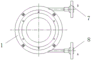
fig. 2 is a schematic view of the back structure of the present invention;
fig. 3 is a schematic view of the top view structure of the present invention.
In the figure: the heat exchanger comprises a heat exchanger body 1, a motor 2, a connecting pipe 3, a wind wing fan blade 4, a fin heat exchange pipe 5, a fixed support 6, a liquid outlet pipe 7 and a liquid inlet pipe 8.
Detailed Description
The following detailed description of the preferred embodiments of the present invention will be provided in conjunction with the accompanying drawings, so that the advantages and features of the present invention can be more easily understood by those skilled in the art, and the protection scope of the present invention can be clearly and clearly defined.
Example (b): referring to fig. 1-3, the present invention provides a technical solution: the utility model provides a force multi-wing fan blade heat exchanger, includes heat exchanger body 1, and motor 2 is installed at the top of heat exchanger body 1, and one side of motor 2 is connected with connecting pipe 3, installs wind wing fan blade 4 in motor 2's the pivot, and the outside of wind wing fan blade 4 is equipped with finned heat exchange tube 5, and one side of heat exchanger body 1 is connected with drain pipe 7, and the opposite side of heat exchanger body 1 is connected with feed liquor pipe 8.
The motor 2 is mounted on the top of the heat exchanger body 1 by bolts and gaskets.
The liquid outlet pipe 7 and the liquid inlet pipe 8 are respectively connected with two ends of the fin heat exchange pipe 5 in a welding mode.
The finned heat exchange tube 5 is installed on one side of the interior of the heat exchanger body 1 through bolts, and the wind wing blades 4 are fixedly connected with a rotating shaft of the motor 2.
The bottom of the heat exchanger body 1 is also provided with a fixed bracket 6.
The motor 2 is either an electric motor or a pneumatic motor.
The working principle is as follows: the utility model provides a force multi-wing fan blade heat exchanger, heat exchanger body 1, motor 2, connecting pipe 3, wind wing fan blade 4, fin heat exchange tube 5, fixed bolster 6, drain pipe 7, feed liquor pipe 8, in the time of the use, it is gaseous to inject into for motor 2 through connecting pipe 3, thereby let the high-speed rotation of pivot in the motor 2, thereby drive wind wing fan blade 4 high-speed rotatory, then discharge the heat on the fin heat exchange tube 5, the liquid of heat transfer passes through drain pipe 7 entering, then discharge through feed liquor pipe 8, thereby reach the effect of heat transfer.
The heat exchanger adopts a bidirectional multi-wing centrifugal wind blade structure, has the advantages of large wind quantity, high wind pressure, high efficiency and the like, and improves the conventional natural air cooling effect; the electric motor is replaced by the motor, so that the explosion-proof problem of the device is solved, energy is saved, and the device is environment-friendly, safe and reliable; the problem that the traditional cooling water is used for cooling to cause equipment scaling so as to influence the use effect is solved, the situation that the device is on site without cooling water is solved, and energy conservation and emission reduction are realized.
The above examples only represent some embodiments of the present invention, and the description thereof is more specific and detailed, but not to be construed as limiting the scope of the present invention. It should be noted that, for those skilled in the art, without departing from the spirit of the present invention, several variations and modifications can be made, which are within the scope of the present invention.
Claims (6)
1. The utility model provides a force multi-wing fan blade heat exchanger, includes heat exchanger body (1), its characterized in that: motor (2) are installed at the top of heat exchanger body (1), one side of motor (2) is connected with connecting pipe (3), install wind wing fan blade (4) in the pivot of motor (2), the outside of wind wing fan blade (4) is equipped with fin heat exchange tube (5), one side of heat exchanger body (1) is connected with drain pipe (7), the opposite side of heat exchanger body (1) is connected with feed liquor pipe (8).
2. The forced multi-wing fan blade heat exchanger of claim 1, wherein: the motor (2) is installed on the top of the heat exchanger body (1) through bolts and sealing gaskets.
3. The forced multi-wing fan blade heat exchanger of claim 1, wherein: and the liquid outlet pipe (7) and the liquid inlet pipe (8) are respectively connected with two ends of the fin heat exchange pipe (5) in a welding manner.
4. The forced multi-wing fan blade heat exchanger of claim 1, wherein: the fin heat exchange tube (5) is installed on one side of the interior of the heat exchanger body (1) through bolts, and the wind wing blades (4) are fixedly connected with a rotating shaft of the motor (2).
5. The forced multi-wing fan blade heat exchanger of claim 1, wherein: the bottom of the heat exchanger body (1) is also provided with a fixed support (6).
6. The forced multi-wing fan blade heat exchanger of claim 1, wherein: the motor (2) is any one of an electric motor and a pneumatic motor.
Priority Applications (1)
| Application Number | Priority Date | Filing Date | Title |
|---|---|---|---|
| CN202222741077.7U CN218523981U (en) | 2022-10-18 | 2022-10-18 | Forced multi-wing fan blade heat exchanger |
Applications Claiming Priority (1)
| Application Number | Priority Date | Filing Date | Title |
|---|---|---|---|
| CN202222741077.7U CN218523981U (en) | 2022-10-18 | 2022-10-18 | Forced multi-wing fan blade heat exchanger |
Publications (1)
| Publication Number | Publication Date |
|---|---|
| CN218523981U true CN218523981U (en) | 2023-02-24 |
Family
ID=85249033
Family Applications (1)
| Application Number | Title | Priority Date | Filing Date |
|---|---|---|---|
| CN202222741077.7U Active CN218523981U (en) | 2022-10-18 | 2022-10-18 | Forced multi-wing fan blade heat exchanger |
Country Status (1)
| Country | Link |
|---|---|
| CN (1) | CN218523981U (en) |
-
2022
- 2022-10-18 CN CN202222741077.7U patent/CN218523981U/en active Active
Similar Documents
| Publication | Publication Date | Title |
|---|---|---|
| CN106640491A (en) | Efficient and durable special water turbine for cooling tower | |
| CN206707945U (en) | A kind of cooling system of wind turbine power generation unit | |
| CN218523981U (en) | Forced multi-wing fan blade heat exchanger | |
| CN211623710U (en) | Water ring pump case of spiral heat transfer | |
| CN219640761U (en) | Ground source heat pump heat exchanger | |
| JP3241267U (en) | Heat exchange device for cooler | |
| CN214204561U (en) | Combined internal circulation heat dissipation power distribution cabinet | |
| CN210380676U (en) | Energy storage inverter | |
| CN210268296U (en) | Water-filtering air-cooling heat exchanger | |
| CN209943043U (en) | Heat exchange control equipment for gas compressor | |
| CN209672865U (en) | A kind of evaporation type oil cooler | |
| CN209672885U (en) | A kind of spiral interior circularly cooling heat exchanger | |
| CN202326099U (en) | Heat recovery system of water-cooling air compressor | |
| CN205654538U (en) | High -efficient heat dissipation formula rotary -vane vacuum pump system | |
| CN114111376A (en) | Aerodynamic forced turbulent flow fin heat exchanger | |
| CN210422755U (en) | Aluminum plate-fin wet-spraying machine engine water tank | |
| CN210625441U (en) | Cold-heat exchanger | |
| CN214308283U (en) | Energy-efficient heat exchanger based on nested technique | |
| CN218469305U (en) | Air can water heater circulation system | |
| CN216815102U (en) | Forced air cooling radiator | |
| CN214469349U (en) | High efficiency pipeline formula electric heater | |
| CN216815121U (en) | High-efficient calandria heat exchanger | |
| CN2413234Y (en) | Geothermal heat exchanging system | |
| CN218155615U (en) | Efficient cooling tower | |
| CN220339165U (en) | Pre-condensation heat energy recovery device for carbon dioxide energy storage system |
Legal Events
| Date | Code | Title | Description |
|---|---|---|---|
| GR01 | Patent grant | ||
| GR01 | Patent grant |