CN218516933U - Wet electrostatic dust collector - Google Patents
Wet electrostatic dust collector Download PDFInfo
- Publication number
- CN218516933U CN218516933U CN202222635610.1U CN202222635610U CN218516933U CN 218516933 U CN218516933 U CN 218516933U CN 202222635610 U CN202222635610 U CN 202222635610U CN 218516933 U CN218516933 U CN 218516933U
- Authority
- CN
- China
- Prior art keywords
- electrostatic precipitator
- wet electrostatic
- casing
- anode tube
- corona wire
- Prior art date
- Legal status (The legal status is an assumption and is not a legal conclusion. Google has not performed a legal analysis and makes no representation as to the accuracy of the status listed.)
- Active
Links
Images


Classifications
-
- Y—GENERAL TAGGING OF NEW TECHNOLOGICAL DEVELOPMENTS; GENERAL TAGGING OF CROSS-SECTIONAL TECHNOLOGIES SPANNING OVER SEVERAL SECTIONS OF THE IPC; TECHNICAL SUBJECTS COVERED BY FORMER USPC CROSS-REFERENCE ART COLLECTIONS [XRACs] AND DIGESTS
- Y02—TECHNOLOGIES OR APPLICATIONS FOR MITIGATION OR ADAPTATION AGAINST CLIMATE CHANGE
- Y02A—TECHNOLOGIES FOR ADAPTATION TO CLIMATE CHANGE
- Y02A50/00—TECHNOLOGIES FOR ADAPTATION TO CLIMATE CHANGE in human health protection, e.g. against extreme weather
- Y02A50/20—Air quality improvement or preservation, e.g. vehicle emission control or emission reduction by using catalytic converters
- Y02A50/2351—Atmospheric particulate matter [PM], e.g. carbon smoke microparticles, smog, aerosol particles, dust
Landscapes
- Electrostatic Separation (AREA)
Abstract
Description
技术领域technical field
本实用新型涉及一种湿式静电除尘器。The utility model relates to a wet electrostatic precipitator.
背景技术Background technique
湿式静电除尘器,用喷水或溢流水等方式使集尘极表面形成一层水膜,实现极板清灰的静电除尘器。湿式清灰可以避免沉集粉尘的再飞扬,达到很高的除尘效率。因无振打装置,运行较稳定。公开号为CN210207224U的专利:一种湿式静电除尘器,所述湿式静电除尘器的塔体底部设置有进气口,湿式静电除尘器的塔体顶部设置有出气口,湿式静电除尘器的塔体内部设置有收尘单元;所述收尘单元包括至少一个收尘模块,所述收尘模块包括立式布置的阳极管以及设置于阳极管中心的电晕线,所述阳极管为正六边形阳极管,相邻的正六边形阳极管共用一条边;所述湿式静电除尘器的塔顶外部设置有至少一个绝缘箱,所述绝缘箱与收尘单元的电晕线连接。其虽使用电晕线替代柔性电极,克服了柔性电极需要重锤吊挂的缺陷,且收尘单元底部不需要设置底部电极定位与限位装置,克服了因定位与限位装置的绝缘故障造成的暂时短路的问题,提高了湿式静电除尘器运行的稳定性。但对于蜂窝型阳极管的形式,其仍旧采用的是正六边形管的形式,产生的电场并不均匀,未能达到较好地除尘效果。Wet electrostatic precipitator is an electrostatic precipitator that uses water spray or overflow water to form a water film on the surface of the dust collector to realize the dust removal of the electrode plate. Wet dust cleaning can avoid the re-flying of deposited dust and achieve high dust removal efficiency. Because there is no rapping device, the operation is more stable. The patent with the publication number CN210207224U: a wet electrostatic precipitator, the bottom of the wet electrostatic precipitator is provided with an air inlet, the top of the wet electrostatic precipitator is provided with an air outlet, and the wet electrostatic precipitator is equipped with an air outlet. A dust collection unit is provided inside; the dust collection unit includes at least one dust collection module, the dust collection module includes a vertically arranged anode tube and a corona wire arranged in the center of the anode tube, and the anode tube is a regular hexagon Anode tubes, adjacent regular hexagonal anode tubes share one side; at least one insulating box is arranged outside the tower top of the wet electrostatic precipitator, and the insulating box is connected to the corona wire of the dust collection unit. Although it uses corona wires instead of flexible electrodes, it overcomes the defect that flexible electrodes need to be hung by heavy hammers, and there is no need to install bottom electrode positioning and limiting devices at the bottom of the dust collection unit, which overcomes the problem caused by the insulation failure of positioning and limiting devices. The problem of temporary short circuit improves the stability of wet electrostatic precipitator operation. However, for the form of the honeycomb anode tube, it is still in the form of a regular hexagonal tube, and the generated electric field is not uniform, and a good dust removal effect cannot be achieved.
实用新型内容Utility model content
本实用新型的目的在于,克服现有技术中存在的缺陷,提供一种湿式静电除尘器,阳极管采用内圆外方(准确地说是内圆外六边形)的形式,使得在电晕线(阴极)和阳极管阳极之间形成的电场更均匀,捕集粉尘效果更佳,除尘效果得到提高。The purpose of this utility model is to overcome the defects existing in the prior art, and to provide a wet electrostatic precipitator. The electric field formed between the wire (cathode) and the anode of the anode tube is more uniform, the dust collection effect is better, and the dust removal effect is improved.
为实现上述目的,本实用新型的技术方案是设计一种湿式静电除尘器,包括湿式静电除尘器壳体,壳体内设有若干组收尘模块,壳体上部设有排气口、壳体下部设有进气口,每个收尘模块包括作为框架的矩形环,矩形环内设置若干个相互紧邻设置的阳极管,阳极管中心设有电晕线,阳极管的垂直于其长度方向的截面形状为双环形且内环为圆形外环为六边形。阳极管采用内圆外方(准确地说是内圆外六边形)的形式,使得在电晕线(阴极)和阳极管阳极之间形成的电场更均匀,能够在流场内使气流紧缩和气流扩大,进而影响离子风涡旋对流场扰动的强弱,更容易捕集一些沿气流方向运动的粉尘,从而提高除尘器的除尘效率,捕集粉尘效果更佳,除尘效果得到提高。In order to achieve the above purpose, the technical solution of the utility model is to design a wet electrostatic precipitator, which includes a wet electrostatic precipitator shell, and several groups of dust collection modules are arranged in the shell, the upper part of the shell is provided with an exhaust port, and the lower part of the shell is There is an air inlet, and each dust collection module includes a rectangular ring as a frame. Several anode tubes are arranged next to each other in the rectangular ring. The center of the anode tube is provided with a corona wire. The cross section of the anode tube perpendicular to its length direction The shape is double ring and the inner ring is circular and the outer ring is hexagonal. The anode tube adopts the form of an inner circle and an outer square (accurately, an inner circle and an outer hexagon), so that the electric field formed between the corona wire (cathode) and the anode of the anode tube is more uniform, and the airflow can be compressed in the flow field And the airflow expands, which in turn affects the strength of the ion wind vortex on the disturbance of the flow field, and it is easier to capture some dust moving along the direction of the airflow, thereby improving the dust removal efficiency of the dust collector, better dust collection effect, and improved dust removal effect.
进一步的技术方案是,矩形环竖直设置且其下端面呈与水平面倾斜的斜面,矩形环的上端面呈与水平面平行的平面;阳极管的下端面也呈与水平面倾斜设置的斜面。矩形环的设置有利于湿式静电除尘器的安装与维护,也降低了每根正六边形阳极管中心处电晕线的固定难度,从而通过省略收尘模块底部的电极定位与限位装置克服了因绝缘问题带来的暂时短路问题,使湿式静电除尘器能够稳定运行;而矩形环下端面斜面的设置则更便于阳极管的安装。A further technical solution is that the rectangular ring is arranged vertically and its lower end face is inclined to the horizontal plane, the upper end face of the rectangular ring is a plane parallel to the horizontal plane; the lower end face of the anode tube is also inclined to the horizontal plane. The setting of the rectangular ring is conducive to the installation and maintenance of the wet electrostatic precipitator, and also reduces the difficulty of fixing the corona wire at the center of each regular hexagonal anode tube, thereby eliminating the need for electrode positioning and limiting devices at the bottom of the dust collection module. The temporary short circuit problem caused by the insulation problem enables the wet electrostatic precipitator to operate stably; and the setting of the slope on the lower end of the rectangular ring is more convenient for the installation of the anode tube.
进一步的技术方案是,每个收尘模块包括一个作为外框的方管,方管内填充设有若干个相互紧邻设置的矩形环。将每个收尘模块设置成由几个矩形环构成,更便于阳极管的布置安装。A further technical solution is that each dust collection module includes a square tube as an outer frame, and the square tube is filled with several rectangular rings arranged adjacent to each other. Each dust collection module is set to be composed of several rectangular rings, which is more convenient for the arrangement and installation of the anode tubes.
进一步的技术方案为,相邻方管固定连接,最靠近湿式静电除尘器壳体的方管固定连接在湿式静电除尘器壳体的内侧壁上;所述电晕线采用不锈钢线,所述阳极管采用玻璃钢材质制成。A further technical solution is that the adjacent square tubes are fixedly connected, and the square tube closest to the wet electrostatic precipitator shell is fixedly connected on the inner side wall of the wet electrostatic precipitator shell; the corona wire is made of stainless steel wire, and the anode The tube is made of fiberglass.
进一步的技术方案为,电晕线其上端超出阳极管设置且此超出端固定连接在湿式静电除尘器壳体顶部的绝缘箱上,位于湿式静电除尘器壳体内顶壁与阳极管上端之间设有固定连接在湿式静电除尘器壳体内侧壁的横梁,电晕线还与横梁固定相连。使用电晕线替代柔性电极,克服了柔性电极需要重锤吊挂的缺陷。A further technical solution is that the upper end of the corona wire is set beyond the anode tube and the excess end is fixedly connected to the insulating box on the top of the wet electrostatic precipitator shell, and is located between the top wall of the wet electrostatic precipitator shell and the upper end of the anode tube. There is a beam fixedly connected to the inner wall of the shell of the wet electrostatic precipitator, and the corona wire is also fixedly connected to the beam. Using corona wires instead of flexible electrodes overcomes the defect that flexible electrodes need to be hung by heavy hammers.
本实用新型的优点和有益效果在于:阳极管采用内圆外方(准确地说是内圆外六边形)的形式,使得在电晕线(阴极)和阳极管阳极之间形成的电场更均匀,能够在流场内使气流紧缩和气流扩大,进而影响离子风涡旋对流场扰动的强弱,更容易捕集一些沿气流方向运动的粉尘,从而提高除尘器的除尘效率,捕集粉尘效果更佳,除尘效果得到提高。The utility model has the advantages and beneficial effects that: the anode tube adopts the form of an inner circle and an outer square (to be exact, an inner circle and an outer hexagon), so that the electric field formed between the corona wire (cathode) and the anode of the anode tube is more compact. Uniformity can make the airflow shrink and expand in the flow field, thereby affecting the strength of the ion wind vortex on the flow field disturbance, and it is easier to capture some dust moving along the direction of the airflow, thereby improving the dust removal efficiency of the dust collector and capturing The dust effect is better and the dust removal effect is improved.
矩形环的设置有利于湿式静电除尘器的安装与维护,也降低了每根正六边形阳极管中心处电晕线的固定难度,从而通过省略收尘模块底部的电极定位与限位装置克服了因绝缘问题带来的暂时短路问题,使湿式静电除尘器能够稳定运行;而矩形环下端面斜面的设置则更便于阳极管的安装。The setting of the rectangular ring is conducive to the installation and maintenance of the wet electrostatic precipitator, and also reduces the difficulty of fixing the corona wire at the center of each regular hexagonal anode tube, thereby eliminating the need for electrode positioning and limiting devices at the bottom of the dust collection module. The temporary short circuit problem caused by the insulation problem enables the wet electrostatic precipitator to operate stably; and the setting of the slope on the lower end of the rectangular ring is more convenient for the installation of the anode tube.
使用电晕线替代柔性电极,克服了柔性电极需要重锤吊挂的缺陷。将每个收尘模块设置成由几个矩形环构成,更便于阳极管的布置安装。Using corona wires instead of flexible electrodes overcomes the defect that flexible electrodes need to be hung by heavy hammers. Each dust collection module is set to be composed of several rectangular rings, which is more convenient for the arrangement and installation of the anode tubes.
附图说明Description of drawings
图1是本实用新型一种湿式静电除尘器的示意图;Fig. 1 is the schematic diagram of a kind of wet electrostatic precipitator of the present utility model;
图2是图1的主视图;Fig. 2 is the front view of Fig. 1;
图3是图1中方管的俯视图;Fig. 3 is the top view of square tube in Fig. 1;
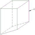
图4是图3中矩形环的立体图。Fig. 4 is a perspective view of the rectangular ring in Fig. 3 .
图中:1、湿式静电除尘器壳体;2、排气口;3、进气口;4、矩形环;5、阳极管;6、电晕线;7、方管;8、绝缘箱;9、横梁。In the figure: 1. Shell of wet electrostatic precipitator; 2. Exhaust port; 3. Air inlet; 4. Rectangular ring; 5. Anode tube; 6. Corona wire; 7. Square tube; 8. Insulation box; 9. Beam.
具体实施方式Detailed ways
下面结合附图和实施例,对本实用新型的具体实施方式作进一步描述。以下实施例仅用于更加清楚地说明本实用新型的技术方案,而不能以此来限制本实用新型的保护范围。Below in conjunction with accompanying drawing and embodiment, the specific embodiment of the utility model is further described. The following examples are only used to illustrate the technical solution of the utility model more clearly, but not to limit the protection scope of the utility model.
如图1至图4所示,本实用新型是一种湿式静电除尘器,包括湿式静电除尘器壳体1,壳体内设有若干组收尘模块,壳体上部设有排气口2、壳体下部设有进气口3,每个收尘模块包括作为框架的矩形环4,矩形环4内设置若干个相互紧邻设置的阳极管5,阳极管5中心设有电晕线6,阳极管5的垂直于其长度方向的截面形状为双环形且内环为圆形外环为六边形。矩形环4竖直设置且其下端面呈与水平面倾斜的斜面,矩形环4的上端面呈与水平面平行的平面;阳极管5的下端面也呈与水平面倾斜设置的斜面。每个收尘模块包括一个作为外框的方管7,方管7内填充设有若干个相互紧邻设置的矩形环4。相邻方管7固定连接,最靠近湿式静电除尘器壳体1的方管7固定连接在湿式静电除尘器壳体1的内侧壁上;所述电晕线6采用不锈钢线,所述阳极管5采用玻璃钢材质制成。电晕线6其上端超出阳极管5设置且此超出端固定连接在湿式静电除尘器壳体1顶部的绝缘箱8上,位于湿式静电除尘器壳体1内顶壁与阳极管5上端之间设有固定连接在湿式静电除尘器壳体1内侧壁的横梁9,电晕线6还与横梁9固定相连。As shown in Figures 1 to 4, the utility model is a wet electrostatic precipitator, including a wet electrostatic precipitator housing 1, several groups of dust collection modules are arranged in the housing, an
工作原理如下:It works as follows:
电晕线(阴极)和阳极管阳极之间形成电场,放电极产生电晕区放电,使空气分子被电离,瞬间产生大量的电子和正、负离子。烟气中的微粒通过该空间时,被强制荷电,粒子间产生凝并,在电场力的作用下作定向运动,达到捕集目的。An electric field is formed between the corona wire (cathode) and the anode of the anode tube, and the discharge electrode generates a corona discharge, which ionizes the air molecules and instantly generates a large number of electrons and positive and negative ions. When the particles in the flue gas pass through the space, they are forced to be charged, and the particles condense and move directionally under the action of the electric field force to achieve the purpose of capture.
阳极管的安装固定方式如下:先在矩形环其倾斜的下端面设置一个与此下端面尺寸形状适配(或比下端面尺寸大的)的挡板,然后将六边形外壁的阳极管逐个置入矩形环内,由于下端面为斜面,所以各个阳极管在置入矩形环内后相互紧邻,然后工人在矩形环上方焊接,然后拿掉下方的挡板,再在下方焊接即可使得阳极管焊接到矩形环上,而相邻阳极管也相互焊接固定连接而成{为避免工人爬上爬下,也可以将矩形环横置,这样只需先用挡板挡住斜面的那一端,然后焊接另一端处的阳极管,再拿掉挡板焊接另一端处的阳极管即可}。The installation and fixing method of the anode tube is as follows: first, a baffle plate matching the size and shape of the lower end surface (or larger than the size of the lower end surface) is set on the inclined lower end surface of the rectangular ring, and then the anode tubes on the hexagonal outer wall are placed one by one. Put it into the rectangular ring, because the lower end face is inclined, so each anode tube is next to each other after being placed in the rectangular ring, and then the worker welds on the top of the rectangular ring, then removes the baffle plate below, and then welds on the bottom to make the anode The tubes are welded to the rectangular ring, and the adjacent anode tubes are also welded and fixedly connected to each other {in order to prevent workers from climbing up and down, the rectangular ring can also be placed horizontally, so that only the end of the inclined plane needs to be blocked by the baffle, and then Weld the anode tube at the other end, then take off the baffle and weld the anode tube at the other end}.
以上所述仅是本实用新型的优选实施方式,应当指出,对于本技术领域的普通技术人员来说,在不脱离本实用新型技术原理的前提下,还可以做出若干改进和润饰,这些改进和润饰也应视为本实用新型的保护范围。The above is only the preferred embodiment of the utility model, and it should be pointed out that for those of ordinary skill in the art, without departing from the technical principle of the utility model, some improvements and modifications can also be made. And retouching should also be regarded as the protection scope of the present utility model.
Claims (5)
Priority Applications (1)
| Application Number | Priority Date | Filing Date | Title |
|---|---|---|---|
| CN202222635610.1U CN218516933U (en) | 2022-10-09 | 2022-10-09 | Wet electrostatic dust collector |
Applications Claiming Priority (1)
| Application Number | Priority Date | Filing Date | Title |
|---|---|---|---|
| CN202222635610.1U CN218516933U (en) | 2022-10-09 | 2022-10-09 | Wet electrostatic dust collector |
Publications (1)
| Publication Number | Publication Date |
|---|---|
| CN218516933U true CN218516933U (en) | 2023-02-24 |
Family
ID=85248490
Family Applications (1)
| Application Number | Title | Priority Date | Filing Date |
|---|---|---|---|
| CN202222635610.1U Active CN218516933U (en) | 2022-10-09 | 2022-10-09 | Wet electrostatic dust collector |
Country Status (1)
| Country | Link |
|---|---|
| CN (1) | CN218516933U (en) |
-
2022
- 2022-10-09 CN CN202222635610.1U patent/CN218516933U/en active Active
Similar Documents
| Publication | Publication Date | Title |
|---|---|---|
| CN208066547U (en) | A kind of wet cottrell | |
| CN201711219U (en) | Semi-moist type electrostatic dust collector | |
| CN105289847A (en) | Static electricity high-efficient collecting device applicable to water mist discharged by wet cooling tower of thermal power plant | |
| CN211026717U (en) | High-efficient negative and positive pole device of electrostatic precipitator | |
| CN200998692Y (en) | Uniform distributed electric field type electric precipitator | |
| CN212633025U (en) | Wet electrostatic precipitator negative pole line weight fixing and adjusting device | |
| CN206027932U (en) | Wet -type electrostatic dust collector | |
| CN102500188A (en) | Wet type electric dust-removing device | |
| CN108144750A (en) | A kind of charged module of particulate matter and electrostatic dust-collecting device | |
| CN211217122U (en) | Supporting high temperature electrostatic precipitator system of cement trade denitration | |
| CN209829270U (en) | Honeycomb tube type wet electrostatic dust collector | |
| CN108067354A (en) | A kind of composite type electrostatic precipitator | |
| CN212596394U (en) | Wet-type electric dust remover for removing corona seal | |
| CN107497603A (en) | A kind of Combined type electric dedusting | |
| CN109013060B (en) | Dry-type electrostatic precipitator of area metal mesh anode plate | |
| CN214320523U (en) | Bipolar droplet trapping device | |
| CN110496707A (en) | An electrostatic precipitator with a coulomb lens anode | |
| CN205966183U (en) | Anode plate and wet -type electrostatic precipitator | |
| CN204447639U (en) | A kind of equipment removing nanoscale dust in gas | |
| CN203791052U (en) | Vertical tube type high-voltage wet-type electrostatic fine dust collector | |
| CN108465558A (en) | A kind of compound dust-collection device based on solar power generation | |
| CN210045400U (en) | Energy-saving emission-reduction electrostatic dust collector capable of preventing secondary dust emission | |
| CN210448379U (en) | Dust removal defogging water trap device of coal fired power plant afterbody flue gas | |
| CN215465187U (en) | High-efficiency multi-pole electrostatic dust collector | |
| CN202387342U (en) | Wet-type electric dedusting device |
Legal Events
| Date | Code | Title | Description |
|---|---|---|---|
| GR01 | Patent grant | ||
| GR01 | Patent grant | ||
| EE01 | Entry into force of recordation of patent licensing contract |
Contract record no.: X2026980016603 Denomination of utility model: A wet electrostatic precipitator Granted publication date: 20230224 License type: Common License Record date: 20260804 |