CN218514838U - Grass smashing and juicing integrated machine - Google Patents
Grass smashing and juicing integrated machine Download PDFInfo
- Publication number
- CN218514838U CN218514838U CN202221883361.1U CN202221883361U CN218514838U CN 218514838 U CN218514838 U CN 218514838U CN 202221883361 U CN202221883361 U CN 202221883361U CN 218514838 U CN218514838 U CN 218514838U
- Authority
- CN
- China
- Prior art keywords
- box
- box body
- handling
- groove
- cutting
- Prior art date
- Legal status (The legal status is an assumption and is not a legal conclusion. Google has not performed a legal analysis and makes no representation as to the accuracy of the status listed.)
- Active
Links
Images


Abstract
The utility model discloses a grass crushing and juicing all-in-one relates to the grass crushing field, including handling the box, the even level of bottom surface of handling the box docks with the bottom cushion block, the bottom surface welding of handling the box has the hopper, a side level of handling the box has seted up the groove of squeezing juice, the inboard side bevel joint of handling the box has the direction bottom plate, adopts the crushing structure of cutting formula to make kibbling more thoroughly high-efficient down, and annular blade roll compression formula is smashed simultaneously and is makeed the jam condition that can not cause the adhesion and form when smashing the grass, and can influence kibbling efficiency after blockking up, and smash and squeeze juice the integrated structure for to the processing higher high efficiency of grass, need not shift to the position processing operation of squeezing juice to the grass after smashing, and shift and smash the material and can cause and drop and form the extravagant condition, can effectually carry out categorised collection to the material squeezing juice and arrange the disconnect-type structure and make the more thorough comprehensive of squeezing juice.
Description
Technical Field
The utility model relates to a technical field is smashed to the forage grass, specifically is a juicing all-in-one is smashed to forage grass.
Background
Forage grass, generally refers to grass or other herbaceous plants that are consumed by raised livestock. The pasture has strong regeneration capacity, can be harvested for many times in one year, and is rich in various trace elements and vitamins, so the pasture becomes the first choice for raising livestock. The quality of the pasture variety directly affects the economic benefit of animal husbandry and needs to be paid attention.
Processing is being add to present forage grass, need smash it and the operation of squeezing juice, traditional crushing and the juice extraction all separately processing operation, it still need carry the inside operation of squeezing juice of the equipment of squeezing juice with the material after smashing still to have leaded to, can cause dropping of material to cause the waste when the transport, the stirring of adopting simultaneously when smashing smashes and makes and to form the jam condition to the inside, can influence the crushing machining efficiency to forage grass after the jam, the operation of squeezing formula has just been adopted to the juice extraction, make the extruded power be restricted and let the rate of forming juice of squeezing juice lower, still need the solitary slag charge to equipment inside to draw out and form the inconvenience.
SUMMERY OF THE UTILITY MODEL
An object of the utility model is to provide a grass is smashed and is squeezed juice all-in-one, with solve to present grass that proposes in the above-mentioned background art and adding man-hour, need smash it and squeeze juice the operation, traditional smashing and squeezing juice all separately processing operation, it still needs to carry the inside juice extraction operation of equipment of squeezing juice with the material after smashing still to have leaded to after smashing, can cause dropping of material to cause the waste when the transport, the stirring of adopting when smashing simultaneously is smashed and is made to form the jam condition to the inside, can influence the crushing machining efficiency to grass after the jam, and squeeze juice has just adopted the operation of extrusion formula, make extruded power limited and let the juice extraction rate of squeezing juice lower, still need solitary to draw out the problem that forms the inconvenience to the inside slag charge of equipment.
In order to achieve the above object, the utility model provides a following technical scheme:
the utility model provides a forage grass crushing and juicing all-in-one, includes the processing box, the even level butt joint in bottom surface of processing box has a bottom cushion, the bottom surface welding of processing box has a batch hopper, the juice groove has been seted up to a side level of processing box, the inboard side oblique welding of processing box has a guide bottom plate, a side of processing box is inlayed and is had control panel, a side horizontal bolted connection of processing box has a side box body, a side box body has a fixed box at a side bolted connection of keeping away from processing box, the top surface level of processing box has seted up the top and has led to the groove, the inboard side horizontal symmetry of processing box is provided with the cutting roller, the inboard side of side box body is provided with transmission gear, the inboard side bolted connection of fixed box has the cutting motor, the inboard side horizontal welding of processing box has the guide hopper, the inboard side symmetric welding of processing box has fixed bottom block, the fixed bottom block of side horizontal fixed joint has a bottom screening plate between the fixed bottom block, the inboard side of processing box is provided with the squeeze roll, the fixed row of squeeze roll has cup jointed the grinding layer, the side of the side edge of processing box is opened to one side oblique and is equipped with the side groove, the even screw hole of seting up of processing box, the fixed bottom block is connected with the grinding screw rod and is connected with the grinding control panel at a side of grinding screw rod of grinding control box.
As a preferred embodiment of the present invention: the number of the bottom cushion blocks is four, the top surfaces of the four bottom cushion blocks are correspondingly butted and arranged at the bottom opening end position of the bottom screw hole one by one, the bottom end of the feeding hopper is vertically butted downwards at the top opening end position of the top through groove, and the inside of the feeding hopper and the inside of the top through groove are mutually communicated and arranged.
As a preferred embodiment of the present invention: arrange juice groove level through type and set up and be close to the bottom surface position at a side of handling the box, and arrange the juice groove level and set up position between fixed bottom block, the one end of direction bottom plate is fixed one side opening bottom surface position that sets up at row juice groove downwards to one side, and the direction bottom plate is the bottom surface position of slope form setting at end screening board.
As a preferred embodiment of the present invention: the fixed setting of side box body level is close to the top position at a side of handling the box, the fixed one side that sets up at the side box body of fixed box is close to one end position, the top is led to the groove level and is seted up and put at the top surface central point of handling the box, and the inside that leads to the groove and the inside of handling the box of top keep leading to and connect the setting, the number of cutting roller is two, and two cutting rollers parallel arrangement each other, the mutual alternating expression of cutting blade that the outside limit of cutting roller set up is arranged, the cutting roller level sets up the inboard of handling the box and is close to the top surface position.
As a preferred embodiment of the present invention: the transmission gear is respectively fixed cup jointing of one-to-one and sets up the one end axle head position at the cutting roller, and the transmission gear setting of toothing each other, and the output level of cutting motor welds the one end axle head position that sets up at a cutting roller, and the end opening end setting that the direction was fought is in the one end top surface position of end screening plate, and the mutual parallel fixed setting of fixed bottom block, end screening plate are the fixed top position that sets up between the fixed bottom block of arc level.
As a preferred embodiment of the present invention: the squeeze roll sets up the circle central point of screening board at the end and puts, and the bottom surface butt joint of grinding layer sets up the top surface position at end screening board, and the side is arranged the groove and is run through the formula and set up the one end position near end screening board, and the output level of grinding motor runs through the lateral wall that handles the box and extends to inside, and extends the end horizontal welding and set up the central point of putting at the squeeze roll.
Compared with the prior art, the beneficial effects of the utility model are that:
the utility model discloses a throw forage grass into the inside of magazine, enter into the inside of handling the box through the top logical groove after falling into downwards, make transmission gear rotating effect under the rotation of cutting motor, make inside cutting roller rotate each other and carry out cutting operation to position between, make the material after smashing fall into the inside of direction fill downwards after cutting smashing with forage grass, then make the crushing material fall into the top surface one end position of end screening board downwards under the direction of direction fill, and make the squeeze roll drive the top surface of wearing layer at end screening board and carry out the rotation effect under the rotation of grinding motor, grind layer and end screening board mutual grinding operation, make the crushing forage grass to position between to extrude the abrasive processing, and the juice filters through end screening board and spills juice material downwards, outwards discharge from the juice discharging groove through the direction of direction bottom plate, and make the top surface residue material of end screening board to the direction motion of side discharge groove under the pivoted drive, through the side discharge collection groove outwards discharge the collection processing, make the crushing material more efficient crushing material that the crushing roller can not cause the effectual crushing juice to press the high-efficient classification condition of squeezing to the jam more, make the crushing material more waste of crushing material to the crushing juice collection after the crushing structure.
Drawings
Other features, objects and advantages of the invention will become more apparent upon reading of the detailed description of non-limiting embodiments with reference to the following drawings:
FIG. 1 is a schematic perspective view of an integrated pasture grass smashing and juicing machine;
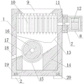
FIG. 2 is a schematic structural diagram of a front section connection detail of a processing box body of the pasture grass smashing and juicing all-in-one machine;
FIG. 3 is a schematic structural view of a top-view section connection detail of a processing box of the pasture grass smashing and juicing all-in-one machine;
fig. 4 is a schematic structural diagram of the side view section connection details of the squeezing roller of the grass smashing and juicing all-in-one machine.
In the figure: 1. a treatment box body; 2. a bottom cushion block; 3. a feeding hopper; 4. a juice draining groove; 5. a guide base plate; 6. a control panel; 7. a side box body; 8. a fixing box; 9. a top through groove; 10. a cutting roller; 11. a transmission gear; 12. cutting the motor; 13. a guide hopper; 14. fixing the bottom block; 15. a bottom screening plate; 16. a squeeze roll; 17. a polishing layer; 18. a side discharge groove; 19. a bottom screw hole; 20. connecting a screw rod; 21. a grinding motor.
Detailed Description
Referring to fig. 1, in the embodiment of the present invention, a pasture grass smashing and juicing integrated machine comprises a processing box body 1, a bottom surface of the processing box body 1 is evenly and horizontally butted with a bottom cushion block 2, a feeding hopper 3 is welded on the bottom surface of the processing box body 1, the number of the bottom cushion blocks 2 is four, top surfaces of the four bottom cushion blocks 2 are all butted and arranged at the bottom opening end position of a bottom screw hole 19 in a one-to-one correspondence manner, the bottom end of the feeding hopper 3 is vertically and downwards butted and arranged at the top opening end position of a top through groove 9, the inside of the feeding hopper 3 and the inside of the top through groove 9 are mutually communicated, a juice discharging groove 4 is horizontally arranged on one side edge of the processing box body 1, a guide bottom plate 5 is obliquely welded on the inner side edge of the processing box body 1, the juice discharging groove 4 is horizontally arranged at a position close to the bottom surface at one side edge of the treatment box body 1 in a penetrating manner, the juice discharging groove 4 is horizontally arranged at a position between the fixed bottom blocks 14, one end of the guide bottom plate 5 is obliquely and downwards fixedly arranged at the bottom surface position of an opening at one side edge of the juice discharging groove 4, the guide bottom plate 5 is obliquely arranged at the bottom surface position of the bottom screening plate 15, a control panel 6 is embedded at one side edge of the treatment box body 1, a side box body 7 is horizontally bolted at one side edge of the treatment box body 1, the side box body 7 is bolted at one side edge far away from the treatment box body 1 and is connected with a fixed box 8, the side box body 7 is horizontally and fixedly arranged at a position close to the top end at one side edge of the side box body 7, and the fixed box 8 is fixedly arranged at a position close to one end at one side edge of the side box body 7;
referring to fig. 2-4, in the embodiment of the present invention, a pasture grass smashing and juicing integrated machine is provided, wherein a top surface of a processing box body 1 is horizontally provided with a top through groove 9, inner side edges of the processing box body 1 are horizontally and symmetrically provided with cutting rollers 10, the top through groove 9 is horizontally provided at a central position of the top surface of the processing box body 1, the inside of the top through groove 9 is communicated with the inside of the processing box body 1, the number of the cutting rollers 10 is two, the two cutting rollers 10 are arranged in parallel, cutting blades arranged at outer side edges of the cutting rollers 10 are arranged in a staggered manner, the cutting rollers 10 are horizontally arranged at a position close to the top surface at the inner side of the processing box body 1, an inner side edge of a side box body 7 is provided with a transmission gear 11, an inner side edge of a fixing box 8 is bolted with a cutting motor 12, an inner side edge of the processing box body 1 is horizontally welded with a guide hopper 13, inner side edge of the processing box body 1 is symmetrically welded with a fixing bottom block 14, a bottom screening plate 15 is horizontally and fixedly clamped between the fixed bottom blocks 14 at the side edge, the transmission gears 11 are respectively fixedly sleeved at the shaft end position of one end of the cutting roller 10 in a one-to-one correspondence manner, the transmission gears 11 are arranged in a tooth joint manner, the output end of the cutting motor 12 is horizontally welded at the shaft end position of one end of one cutting roller 10, the bottom open end of the guide hopper 13 is arranged at the top surface position of one end of the bottom screening plate 15, the fixed bottom blocks 14 are fixedly arranged in parallel, the bottom screening plate 15 is fixedly arranged at the top end position between the fixed bottom blocks 14 in an arc-shaped horizontal manner, an extrusion roller 16 is arranged at the inner side edge of the processing box body 1, a grinding layer 17 is fixedly sleeved at the outer side edge of the extrusion roller 16, a side discharge groove 18 is obliquely arranged at one side edge of the processing box body 1, bottom screw holes 19 are uniformly arranged at the bottom surface of the processing box body 1, and connecting screw rods 20 are fixedly inserted at the top surface of the bottom cushion block 2, handle box 1 and have grinding motor 21 at a side bolted connection who keeps away from control panel 6, squeeze roll 16 sets up the round central point who puts at end screening plate 15, and the bottom surface butt joint of grinding layer 17 sets up the top surface position at end screening plate 15, side discharge chute 18 runs through the formula and sets up the one end position near end screening plate 15, grinding motor 21's output level runs through the lateral wall that handles box 1 and extends to inside, and extend end horizontal welding and set up the central point who puts at squeeze roll 16.
The components are standard parts in general or known to those skilled in the art, and their structure and principle are known to those skilled in the art through technical manuals or through routine experimentation.
The utility model discloses a theory of operation is:
forage grass is fed into a feeding hopper 3, the forage grass enters the treatment box body 1 through a top through groove 9 after falling downwards, a transmission gear 11 rotates under the rotation of a cutting motor 12, cutting operation is carried out on the positions between the cutting rollers 10 in the forage grass by rotating mutually, the forage grass is cut and crushed, the crushed material falls downwards into a guide hopper 13, then the crushed material falls downwards into one end of the top surface of a bottom screening plate 15 under the guide of the guide hopper 13, a grinding layer 17 is driven by an extrusion roller 16 to rotate on the top surface of the bottom screening plate 15 under the rotation of a grinding motor 21, the crushed forage grass in the positions between is subjected to extrusion grinding treatment on the grinding layer 17 and the bottom screening plate 15, ground juice is screened through the bottom screening plate 15 to leak the juice downwards, the juice is discharged outwards from a juice discharge groove 4 through the guide of a guide bottom base plate 5, and the juice is moved towards the top surface of a side screening plate 15 under the rotation drive to be discharged outwards through a side discharge groove 18 for collection treatment.
The above-mentioned, only be the concrete implementation of the preferred embodiment of the present invention, but the protection scope of the present invention is not limited thereto, and any person skilled in the art is in the technical scope of the present invention, according to the technical solution of the present invention and the utility model, the concept of which is equivalent to replace or change, should be covered within the protection scope of the present invention.
Claims (6)
1. The utility model provides a grass smashing and juicing all-in-one machine, includes handles box (1), its characterized in that, the even level butt joint in bottom pad (2) of the bottom surface of handling box (1), the bottom surface welding of handling box (1) has hopper (3), juice discharging groove (4) have been seted up to a side level of handling box (1), the inboard side oblique welding of handling box (1) has guide bottom plate (5), a side of handling box (1) is inlayed and is had control panel (6), a side horizontal bolted connection of handling box (1) has side box body (7), side box body (7) have fixed box (8) keeping away from a side bolted connection of handling box (1), the inboard side top groove (9) has been seted up to the top surface level of handling box (1), the inboard side horizontal symmetry of handling box (1) is provided with cutting roller (10), the inboard side of side box body (7) is provided with transmission gear (11), the inboard side bolted connection of fixed box (8) has cutting motor (12), the inboard side horizontal guide hopper (13) of handling box (1), the welding of handling box (1) has fixed box (14) the side screening bottom block (14) between the joint of fixed box (14), the outer side edge of the squeeze roll (16) is fixedly sleeved with a grinding layer (17), one side edge of the treatment box body (1) is obliquely provided with a side discharge groove (18), the bottom surface of the treatment box body (1) is uniformly provided with a bottom screw hole (19), the top surface of the bottom cushion block (2) is fixedly inserted with a connecting screw rod (20), and one side edge of the treatment box body (1) far away from the control panel (6) is connected with a grinding motor (21) through a bolt.
2. The pasture grass smashing and juicing all-in-one machine as claimed in claim 1, wherein the number of the bottom cushion blocks (2) is four, the top surfaces of the four bottom cushion blocks (2) are correspondingly butted at the bottom opening end position of the bottom screw hole (19), the bottom end of the feeding hopper (3) is vertically butted downwards at the top opening end position of the top through groove (9), and the interior of the feeding hopper (3) and the interior of the top through groove (9) are communicated with each other.
3. A pasture grass smashing and juicing all-in-one machine as claimed in claim 1, wherein the juice discharging groove (4) is horizontally arranged at a position close to the bottom face on one side edge of the processing box body (1) in a penetrating mode, the juice discharging groove (4) is horizontally arranged between the fixed bottom blocks (14), one end of the guide bottom plate (5) is obliquely and downwards fixedly arranged at the bottom face position of an opening on one side of the juice discharging groove (4), and the guide bottom plate (5) is obliquely arranged at the bottom face position of the bottom screening plate (15).
4. A pasture grass smashing and juicing all-in-one machine as claimed in claim 1, wherein the side box body (7) is horizontally and fixedly arranged at a position close to the top end of one side edge of the processing box body (1), the fixing box (8) is fixedly arranged at a position close to one end of one side edge of the side box body (7), the top through groove (9) is horizontally formed in the center of the top surface of the processing box body (1), the inside of the top through groove (9) is communicated with the inside of the processing box body (1), the number of the cutting rollers (10) is two, the two cutting rollers (10) are arranged in parallel, cutting blades arranged on the outer side edges of the cutting rollers (10) are arranged in a staggered mode, and the cutting rollers (10) are horizontally arranged at a position close to the top surface of the inner side of the processing box body (1).
5. The pasture grass smashing and juicing all-in-one machine as claimed in claim 1, wherein the transmission gears (11) are fixedly sleeved at one end shaft end position of the cutting roller (10) in a one-to-one correspondence mode respectively, the transmission gears (11) are arranged in a tooth joint mode, the output end of the cutting motor (12) is horizontally welded at one end shaft end position of the cutting roller (10), the bottom opening end of the guide hopper (13) is arranged at one end top surface position of the bottom screening plate (15), the fixed bottom blocks (14) are fixedly arranged in parallel, and the bottom screening plate (15) is fixedly arranged at the top end position between the fixed bottom blocks (14) in an arc-shaped horizontal mode.
6. The pasture grass smashing and juicing all-in-one machine is characterized in that the squeezing roller (16) is arranged at the circular center position of the bottom screening plate (15), the bottom surface of the grinding layer (17) is arranged at the top surface position of the bottom screening plate (15) in a butt joint mode, the side discharge groove (18) is arranged at one end position close to the bottom screening plate (15) in a penetrating mode, the output end of the grinding motor (21) horizontally penetrates through the side wall of the processing box body (1) to extend into the processing box body, and the extending end is horizontally welded at the center position of the squeezing roller (16).
Priority Applications (1)
| Application Number | Priority Date | Filing Date | Title |
|---|---|---|---|
| CN202221883361.1U CN218514838U (en) | 2022-07-21 | 2022-07-21 | Grass smashing and juicing integrated machine |
Applications Claiming Priority (1)
| Application Number | Priority Date | Filing Date | Title |
|---|---|---|---|
| CN202221883361.1U CN218514838U (en) | 2022-07-21 | 2022-07-21 | Grass smashing and juicing integrated machine |
Publications (1)
| Publication Number | Publication Date |
|---|---|
| CN218514838U true CN218514838U (en) | 2023-02-24 |
Family
ID=85242562
Family Applications (1)
| Application Number | Title | Priority Date | Filing Date |
|---|---|---|---|
| CN202221883361.1U Active CN218514838U (en) | 2022-07-21 | 2022-07-21 | Grass smashing and juicing integrated machine |
Country Status (1)
| Country | Link |
|---|---|
| CN (1) | CN218514838U (en) |
-
2022
- 2022-07-21 CN CN202221883361.1U patent/CN218514838U/en active Active
Similar Documents
| Publication | Publication Date | Title |
|---|---|---|
| CN213468088U (en) | A reducing mechanism for processing of phosphate food additive production facility | |
| CN206778646U (en) | A kind of fodder grinder | |
| CN215964040U (en) | Food material grinds whitewashed device | |
| CN107413483A (en) | Self-loopa crushing grinding device inside and outside a kind of feed manufacturing use | |
| CN210449386U (en) | Corn grinder is used in corn steep liquor production | |
| CN213528996U (en) | Brown sugar reducing mechanism | |
| CN218514838U (en) | Grass smashing and juicing integrated machine | |
| CN213187264U (en) | Shredding device is used in animal husbandry forage grass processing | |
| CN212468273U (en) | Food processing is with smashing filter equipment | |
| CN211487875U (en) | High-efficient grinder is used in food processing | |
| CN208370885U (en) | A kind of novel granulated feed machine | |
| CN218573816U (en) | Grinder is used in food processing with screening mechanism | |
| CN206821351U (en) | A kind of feed grinder of longitudinally adjust | |
| CN215197141U (en) | Novel smash feed processing equipment of dehydration | |
| CN211660069U (en) | Corn flour mill capable of automatically cleaning screening net | |
| CN213726939U (en) | Reducing mechanism is used in processing of chinese angelica raw and other materials | |
| CN111298924B (en) | Make things convenient for laying hen fodder screening mixing arrangement of unloading | |
| CN210474177U (en) | Pulverizer for processing aquatic feed | |
| CN210580851U (en) | Jam processing equipment for food processing | |
| CN209772307U (en) | Fertilizer production is with high-efficient reducing mechanism | |
| CN215140352U (en) | Feed processing is with reducing mechanism that has loop structure | |
| CN111688254A (en) | Vegetable oil squeezing device for deep processing of food | |
| CN214554157U (en) | Prevent fodder grinder that splashes | |
| CN217093663U (en) | Preparation device of crisp-meat tilapia feed | |
| CN214338767U (en) | Pasture crushing apparatus for animal husbandry |
Legal Events
| Date | Code | Title | Description |
|---|---|---|---|
| GR01 | Patent grant | ||
| GR01 | Patent grant |