CN218514308U - Photovoltaic module - Google Patents
Photovoltaic module Download PDFInfo
- Publication number
- CN218514308U CN218514308U CN202222517838.0U CN202222517838U CN218514308U CN 218514308 U CN218514308 U CN 218514308U CN 202222517838 U CN202222517838 U CN 202222517838U CN 218514308 U CN218514308 U CN 218514308U
- Authority
- CN
- China
- Prior art keywords
- photovoltaic module
- wall
- hypotenuse
- carriage
- piece
- Prior art date
- Legal status (The legal status is an assumption and is not a legal conclusion. Google has not performed a legal analysis and makes no representation as to the accuracy of the status listed.)
- Active
Links
Images


Classifications
-
- Y—GENERAL TAGGING OF NEW TECHNOLOGICAL DEVELOPMENTS; GENERAL TAGGING OF CROSS-SECTIONAL TECHNOLOGIES SPANNING OVER SEVERAL SECTIONS OF THE IPC; TECHNICAL SUBJECTS COVERED BY FORMER USPC CROSS-REFERENCE ART COLLECTIONS [XRACs] AND DIGESTS
- Y02—TECHNOLOGIES OR APPLICATIONS FOR MITIGATION OR ADAPTATION AGAINST CLIMATE CHANGE
- Y02E—REDUCTION OF GREENHOUSE GAS [GHG] EMISSIONS, RELATED TO ENERGY GENERATION, TRANSMISSION OR DISTRIBUTION
- Y02E10/00—Energy generation through renewable energy sources
- Y02E10/50—Photovoltaic [PV] energy
Landscapes
- Photovoltaic Devices (AREA)
Abstract
The utility model relates to a photovoltaic power generation field, concretely designs a photovoltaic module, its technical scheme is: including equipment enclosure, glass is installed at equipment enclosure's top, the fixed block is installed to equipment enclosure's outer wall symmetry, the outer wall of fixed block rotates and installs the carriage, the protection cushion is installed to the outer wall symmetry of carriage, strutting arrangement is installed to equipment enclosure's outer wall, the beneficial effects of the utility model are that: through installing carriage, connecting axle, hypotenuse gear, connecting rod, hypotenuse piece, connecting block realized supporting photovoltaic module's function, rotatory carriage, hypotenuse gear clockwise rotation makes the hypotenuse piece by jack-up, when hypotenuse gear anticlockwise rotation, the hypotenuse piece blocks the hypotenuse gear for the unable anticlockwise rotation of hypotenuse gear makes photovoltaic module's support angle fixed, thereby realized supporting photovoltaic module's function.
Description
Technical Field
The utility model relates to a photovoltaic power generation field, concretely relates to photovoltaic module.
Background
The photovoltaic module generally refers to a solar cell module, generates electric energy through photovoltaic power generation, and the photovoltaic power generation directly converts solar light energy into electric energy by utilizing the photovoltaic module according to a photovoltaic effect, so that the photovoltaic module is safe and reliable, does not generate noise, does not generate pollution, is not limited by resource distribution regions, and can be utilized on roofs of cities and villages.
The prior art has the following defects: current photovoltaic module installs on specific support, need artifical transport or pack the back well and hang through the crane and install, unusual inconvenience, if photovoltaic module combines with the support, will not need to install on the support, can support the use alone, not only practices thrift the installation effectiveness, and the portability also improves greatly moreover.
Therefore, it is necessary to invent a photovoltaic module.
SUMMERY OF THE UTILITY MODEL
For this, the utility model provides a photovoltaic module, through rotatory carriage, hypotenuse gear clockwise rotation makes the hypotenuse piece by jack-up, hypotenuse piece rebound drives the connecting rod rebound in No. two flutings, the spring atress shrink, hypotenuse gear clockwise rotation is unrestricted, make photovoltaic module's support angle can change, when hypotenuse gear anticlockwise rotation, the hypotenuse piece blocks the hypotenuse gear, make the unable anticlockwise rotation of hypotenuse gear, make photovoltaic module's support angle fixed, in order to solve the problem of supporting photovoltaic module.
In order to achieve the above object, the present invention provides the following technical solutions: the utility model provides a photovoltaic module, includes the equipment shell, glass is installed at the top of equipment shell, the fixed block is installed to the outer wall symmetry of equipment shell, and the fixed block has four, the outer wall of fixed block rotates installs the carriage, the protection cushion is installed to the outer wall symmetry of carriage, strutting arrangement is installed to the outer wall of equipment shell.
Preferably, the supporting device comprises a connecting shaft, the connecting shaft is symmetrically installed on the inner wall of the supporting frame, and the bevel gear is installed at one end of the connecting shaft.
Preferably, the inner wall of the fixed block is provided with a first slot, and the top of the fixed block is provided with a second slot.
Preferably, no. two grooved inner wall slidable mounting have the connecting rod, the connecting rod extends to No. two grooved inner walls, and No. two grooved and connecting rod's bottom location is connected, no. two grooved outer walls encircle installs the spring, the connecting block is installed at the top of connecting rod, the bevel piece is installed to the bottom of connecting rod.
Preferably, the inner wall of the supporting frame is symmetrically provided with a first sliding rail, and the top of the supporting frame is symmetrically provided with a second sliding rail.
Preferably, the inner wall slidable mounting of a slide rail has a bracing piece, no. two bracing pieces are installed to the one end of a bracing piece, the screwed pipe has been seted up at the top of a bracing piece, the threaded rod is installed to the inner wall of screwed pipe, and screwed pipe and threaded rod meshing, the knob is installed to the one end of threaded rod.
The utility model has the advantages that:
1. the utility model discloses an install the carriage, the connecting axle, the hypotenuse gear, the connecting rod, the hypotenuse piece, the connecting block has realized the function of supporting photovoltaic module, rotatory carriage, hypotenuse gear clockwise rotates and makes the hypotenuse piece by jack-up, hypotenuse piece moves upward and drives the connecting rod upwards to move in No. two flutings, the spring atress shrinks, hypotenuse gear clockwise rotates unrestricted, make photovoltaic module's support angle change, when hypotenuse gear anticlockwise rotates, the hypotenuse piece blocks the hypotenuse gear, make the hypotenuse gear can't anticlockwise rotate, make photovoltaic module's support angle fixed, move the connecting block upwards, the connecting block moves upward and drives the hypotenuse piece to move upward, the hypotenuse piece moves upward and makes the hypotenuse gear can anticlockwise rotate again, thereby realized the function of supporting photovoltaic module;
2. the utility model discloses an install a bracing piece, no. two bracing pieces, the screwed pipe, the knob, the threaded rod has realized the function of adjusting the photovoltaic module height, when needing to adjust photovoltaic module's height, it makes knob and carriage separately to rotate the knob, a bracing piece removes on a slide rail, the threaded rod removes on No. two slide rails, make the height of No. two bracing pieces can adjust, the antiport knob makes the threaded rod get into the screwed pipe, the knob is laminated with the carriage, a bracing piece is fixed, thereby the function of adjusting the photovoltaic module height has been realized.
Drawings
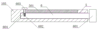
Fig. 1 is a schematic top view of the present invention;
FIG. 2 is a schematic view of the internal structure of the side of the support frame provided by the present invention;
fig. 3 is a schematic view of the internal structure of the side of the fixed block provided by the present invention;
fig. 4 is a schematic view of a partial structure of the rotating device provided by the present invention.
In the figure: 1. an equipment enclosure; 101. glass; 102. a fixed block; 103. a support frame; 104. protecting the soft cushion; 2. a connecting shaft; 201. a bevel gear; 3. grooving I; 301. grooving for the second time; 4. a connecting rod; 401. a spring; 402. a bevel edge block; 403. connecting blocks; 5. a first slide rail; 501. a second sliding rail; 6. a first support rod; 601. a second support rod; 602. a threaded pipe; 603. a knob; 604. a threaded rod.
Detailed Description
The preferred embodiments of the present invention will be described hereinafter with reference to the accompanying drawings, and it should be understood that the preferred embodiments described herein are merely for purposes of illustration and explanation, and are not intended to limit the present invention.
Referring to the attached drawings 1-4, the utility model provides a pair of photovoltaic module, including equipment shell 1, glass 101 is installed at equipment shell 1's top, fixed block 102 is installed to equipment shell 1's outer wall symmetry, and fixed block 102 has four, carriage 103 is installed in the outer wall rotation of fixed block 102, protection cushion 104 is installed to carriage 103's outer wall symmetry, strutting arrangement is installed to equipment shell 1's outer wall, glass 101's effect is the protection inner structure, and be convenient for printing opacity, a carriage 103 is fixed to two fixed blocks 102, protection cushion 104 is made by the pearl cotton, protection cushion 104's effect prevents that the side from dropping or the side can play the effect of buffering when receiving the striking.
Connecting shaft 2 is installed to the inner wall symmetry of carriage 103, hypotenuse gear 201 is installed to the one end of connecting shaft 2, no. one fluting 3 has been seted up to the inner wall of fixed block 102, no. two fluting 301 have been seted up at the top of fixed block 102, no. two inner wall slidable mounting of fluting 301 has connecting rod 4, connecting rod 4 extends to No. two fluting 301 inner walls, and No. two fluting 301 are connected with the bottom location of connecting rod 4, no. two outer walls encircleing of fluting 301 installs spring 401, connecting block 403 is installed at the top of connecting rod 4, hypotenuse piece 402 is installed to the bottom of connecting rod 4, two connecting shaft 2 on carriage 103 insert make carriage 103 and fixed block 102 rotate in No. one fluting 3 in the fixed block 102 in, hypotenuse gear 201 on connecting shaft 2 rotates in No. one fluting 3, spring 401's effect makes connecting rod 4 reset fast, no. two fluting 301's effect provides space for the removal of connecting rod 4, rotatory carriage 103, hypotenuse piece 201 rotates makes hypotenuse piece 402 unlimited by the top, hypotenuse piece 402 is moved upwards to drive connecting rod 4 and moved the hypotenuse piece 201 and can not move when the hypotenuse piece moves the hypotenuse piece, thereby make the hypotenuse piece move the hypotenuse piece 201 can not rotate the photovoltaic gear 201 and can move the photovoltaic gear move the anticlockwise pivoted clockwise, make the hypotenuse piece move upward atress that the hypotenuse piece 201, make the hypotenuse move, thereby make the hypotenuse piece move upward movement of supporting function of supporting 201 can be changed, make the hypotenuse piece move the photovoltaic gear 201 that the hypotenuse piece move upwards, make the hypotenuse piece move the hypotenuse piece 201, make the hypotenuse piece move upwards, thereby make the hypotenuse piece move the photovoltaic gear 201 can not to realize the anticlockwise.
The utility model discloses a use as follows: the technical personnel in the field rotate the support frame 103, the bevel gear 201 rotates clockwise to enable the bevel block 402 to be jacked up, the bevel block 402 moves upwards to drive the connecting rod 4 to move upwards in the second groove 301, the spring 401 is stressed to contract, the bevel gear 201 rotates clockwise without limitation, the supporting angle of the photovoltaic module can be changed, when the bevel gear 201 rotates anticlockwise, the bevel block 402 blocks the bevel gear 201, the bevel gear 201 cannot rotate anticlockwise, the supporting angle of the photovoltaic module is fixed, the connecting block 403 moves upwards, the connecting block 403 drives the bevel block 402 to move upwards, the bevel block 402 moves upwards to enable the bevel gear 201 to rotate anticlockwise again, the function of supporting the photovoltaic module is achieved, when the height of the photovoltaic module needs to be adjusted, the knob 603 is rotated to enable the knob 603 to be separated from the support frame 103, the first support rod 6 moves on the first slide rail 5, the second support rod 604 moves on the second slide rail 501, the height of the second support rod 601 can be adjusted, the knob is rotated reversely to enable the threaded rod to enter the threaded pipe 602, the knob 603 is attached to the support frame 103, the first support rod 6 is attached, and the photovoltaic module is fixed, thereby achieving the function of adjusting the photovoltaic module.
The above description is only a preferred embodiment of the present invention, and any person skilled in the art may modify the present invention or modify it into an equivalent technical solution by using the technical solutions described above. Therefore, any simple modifications or equivalent replacements made according to the technical solution of the present invention belong to the scope of the claimed invention as far as possible.
Claims (6)
1. A photovoltaic module comprising an equipment enclosure (1), characterized in that: glass (101) are installed at the top of equipment shell (1), fixed block (102) are installed to the outer wall symmetry of equipment shell (1), and fixed block (102) have four, carriage (103) are installed in the outer wall rotation of fixed block (102), protection cushion (104) are installed to the outer wall symmetry of carriage (103), strutting arrangement is installed to the outer wall of equipment shell (1).
2. A photovoltaic module according to claim 1, wherein: the supporting device comprises a connecting shaft (2), the connecting shaft (2) is symmetrically installed on the inner wall of the supporting frame (103), and the bevel gear (201) is installed at one end of the connecting shaft (2).
3. A photovoltaic module according to claim 1, wherein: the inner wall of the fixing block (102) is provided with a first notch (3), and the top of the fixing block (102) is provided with a second notch (301).
4. A photovoltaic module according to claim 3, wherein: no. two inner wall slidable mounting of fluting (301) has connecting rod (4), connecting rod (4) extend to No. two fluting (301) inner walls, and No. two fluting (301) are connected with the bottom location of connecting rod (4), no. two outer walls of fluting (301) encircle and install spring (401), connecting block (403) are installed at the top of connecting rod (4), sloping piece (402) are installed to the bottom of connecting rod (4).
5. A photovoltaic module according to claim 1, wherein: a first sliding rail (5) is symmetrically arranged on the inner wall of the supporting frame (103), and a second sliding rail (501) is symmetrically arranged on the top of the supporting frame (103).
6. A photovoltaic module according to claim 5, characterized in that: inner wall slidable mounting of a slide rail (5) has bracing piece (6) No. one, bracing piece (601) No. two are installed to the one end of bracing piece (6), screwed pipe (602) have been seted up at the top of bracing piece (6), threaded rod (604) are installed to the inner wall of screwed pipe (602), and screwed pipe (602) and threaded rod (604) meshing, knob (603) are installed to the one end of threaded rod (604).
Priority Applications (1)
| Application Number | Priority Date | Filing Date | Title |
|---|---|---|---|
| CN202222517838.0U CN218514308U (en) | 2022-09-22 | 2022-09-22 | Photovoltaic module |
Applications Claiming Priority (1)
| Application Number | Priority Date | Filing Date | Title |
|---|---|---|---|
| CN202222517838.0U CN218514308U (en) | 2022-09-22 | 2022-09-22 | Photovoltaic module |
Publications (1)
| Publication Number | Publication Date |
|---|---|
| CN218514308U true CN218514308U (en) | 2023-02-21 |
Family
ID=85214120
Family Applications (1)
| Application Number | Title | Priority Date | Filing Date |
|---|---|---|---|
| CN202222517838.0U Active CN218514308U (en) | 2022-09-22 | 2022-09-22 | Photovoltaic module |
Country Status (1)
| Country | Link |
|---|---|
| CN (1) | CN218514308U (en) |
-
2022
- 2022-09-22 CN CN202222517838.0U patent/CN218514308U/en active Active
Similar Documents
| Publication | Publication Date | Title |
|---|---|---|
| CN107276499A (en) | It is a kind of to be easy to mobile adjustable optical overhead utility | |
| CN210041717U (en) | Solar photovoltaic power generation system | |
| CN217956987U (en) | New energy emergency power generation equipment | |
| CN201319568Y (en) | Worm-gear solar rotation stand | |
| CN218514308U (en) | Photovoltaic module | |
| CN211089534U (en) | Solar panel storage support | |
| CN107888129A (en) | A kind of photovoltaic energy storage device | |
| CN111726060B (en) | Solar cell device suitable for low-light-level power generation | |
| CN214796640U (en) | Can change poster propaganda device for college english of picture | |
| CN212258856U (en) | Novel solar panel installing support | |
| CN210273920U (en) | Photovoltaic power generation device with flexible support | |
| CN108173479A (en) | A kind of household photovoltaic plant that can be kept off the rain automatically | |
| CN213043631U (en) | Distributed corner photovoltaic power generation support | |
| CN217721732U (en) | Photovoltaic power generation system fixing and protecting device | |
| CN220331131U (en) | Wind driven generator base plane processing support tool | |
| CN220022689U (en) | Windproof stable solar photovoltaic power generation equipment | |
| CN216356567U (en) | Green energy-saving high-utilization-rate solar photovoltaic cell panel | |
| CN217406461U (en) | Environment-friendly power generation device for water conservancy and hydropower engineering | |
| CN220137830U (en) | New energy power generation actual measurement demonstration model device | |
| CN215498823U (en) | Photovoltaic solar panel with protection function | |
| CN219740287U (en) | Photovoltaic energy storage device | |
| CN214205423U (en) | Strutting arrangement is used in construction of photovoltaic power generation field | |
| CN218678948U (en) | Auxiliary supporting device for solar power generation | |
| CN219287448U (en) | Mounting bracket for photovoltaic module | |
| CN219227484U (en) | Flexible photovoltaic bracket capable of absorbing wind load |
Legal Events
| Date | Code | Title | Description |
|---|---|---|---|
| GR01 | Patent grant | ||
| GR01 | Patent grant |