CN218484100U - Back rest chair - Google Patents
Back rest chair Download PDFInfo
- Publication number
- CN218484100U CN218484100U CN202222115295.XU CN202222115295U CN218484100U CN 218484100 U CN218484100 U CN 218484100U CN 202222115295 U CN202222115295 U CN 202222115295U CN 218484100 U CN218484100 U CN 218484100U
- Authority
- CN
- China
- Prior art keywords
- transverse plate
- chair
- supporting leg
- bracket
- supporting legs
- Prior art date
- Legal status (The legal status is an assumption and is not a legal conclusion. Google has not performed a legal analysis and makes no representation as to the accuracy of the status listed.)
- Active
Links
Images


Abstract
The utility model relates to a chair field specifically discloses a back chair, including the back of the chair, two handrails, seat, two preceding supporting legs and two back supporting legs, the back of the chair is connected to the handrail rear end, and a preceding supporting leg is connected to each handrail front end, and two back supporting legs are connected to the back of the chair bottom, the front end and the rear end of seat can reciprocate respectively outside the ground cover locates preceding supporting leg and back supporting leg, the seat is settled on a bracket, and the front end and the rear end of bracket also overlap respectively and locate preceding supporting leg and back supporting leg outside, and each preceding supporting leg is located the bracket below and wears to establish a preceding anticreep post that holds off the bracket front end, and each back supporting leg is located the bracket below and wears to establish a back anticreep post that holds off the bracket rear end. The simple structure of this product, easy dismounting, the degree of difficulty is low, and is fast, efficient, even children also can independently accomplish the installation, can also regard as children's toy to use, development children intelligence.
Description
Technical Field
The utility model relates to the field of chairs, in particular to a backrest chair.
Background
Most of chairs in the current market are fixed through parts such as screw bolts, and the disassembly and assembly are inconvenient, complex in structure, large in disassembly and assembly difficulty, slow in speed, low in efficiency, difficult to guarantee the comfort, especially incapable of independently completing the installation for children, and limited in function, and the chairs can only be used as chairs.
Disclosure of Invention
In order to solve the problems, the utility model provides a backrest chair which has simple structure, convenient assembly and disassembly and fast speed, can be independently installed even for children and can also be used as a toy for children.
In order to achieve the above purpose, the utility model provides a following technical scheme: the utility model provides a backrest chair, includes the back of the chair, two handrails, seat, two preceding supporting legs and two back supporting legs, and the back of the chair is connected to the handrail rear end, and a preceding supporting leg is connected to each handrail front end, and two back supporting legs are connected to the back of the chair bottom, the front end and the rear end of seat cover can reciprocate respectively outside locating preceding supporting leg and back supporting leg, the seat is settled on a bracket, and the front end and the rear end of bracket also overlap respectively outside locating preceding supporting leg and back supporting leg, and each preceding supporting leg is located the bracket below and wears to establish a preceding anticreep post that holds off the bracket front end, and each back supporting leg is located the bracket below and wears to establish a back anticreep post that holds off the bracket rear end. The chair seat is simple in structure and low in manufacturing cost, the chair seat is supported by the bracket, the front anti-falling column and the rear anti-falling column, firmness is good, the structure is simple, disassembly and assembly are convenient, and efficiency is high; even children also can independently accomplish the dismouting, can also regard as children's toy, develop children's intelligence, promote children to move brain thinking, further expanded service function.
Furthermore, the bracket comprises a first pad body, a second frame body and a decorative frame body which are arranged in sequence, wherein the first pad body is attached to the chair surface, and the decorative frame body is attached to the front anti-falling column and the rear anti-falling column. The first cushion body is soft in material, the contact area of the bracket on the seat surface is improved, the use comfort is improved, the structural firmness is ensured by the second frame body, and the appearance is ensured to be attractive by the decorative frame body.
Furthermore, the first cushion body comprises a first front cushion body, a first rear cushion body and a first middle cushion body clamped between the first front cushion body and the first rear cushion body, two ends of the first front cushion body are respectively sleeved on the two front supporting legs, and two ends of the first rear cushion body are respectively sleeved on the two rear supporting legs. The design structure is simple, and the buffering effect is good.
Furthermore, the second frame body comprises a second front transverse plate, a second rear transverse plate and a second middle plate connected between the second front transverse plate and the second rear transverse plate, and the second front transverse plate, the second rear transverse plate and the second middle plate are of an integral structure; two ends of the second front transverse plate are respectively sleeved on the two front supporting legs, and two ends of the second rear transverse plate are respectively sleeved on the two rear supporting legs. The design structure is simple, and the supporting firmness is strong.
Furthermore, the decorative frame body comprises a third front transverse plate, a third rear transverse plate and a third middle plate clamped between the third front transverse plate and the third rear transverse plate, two ends of the third front transverse plate are respectively sleeved on the two front supporting legs, two ends of the third rear transverse plate are respectively sleeved on the two rear supporting legs, and the bottom surface of the third front transverse plate is tightly attached to the front anti-falling column; the bottom surface of the third rear transverse plate is tightly attached to the rear anti-drop column. The design structure is simple, and the decorative effect is good.
To sum up, the utility model has the advantages that: the simple structure of this product, easy dismounting, the degree of difficulty is low, and is fast, efficient, even children also can independently accomplish the installation, can also regard as children's toy to use, development children intelligence.
Drawings
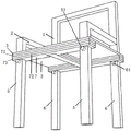
FIG. 1 is a first schematic structural diagram of the present invention;
FIG. 2 is a schematic view of a part of the structure of the present invention;
FIG. 3 is a schematic view of a part of the structure of the present invention;
FIG. 4 is a second schematic structural view of the present invention;
wherein, the chair back 1; a handrail 2; a seat surface 3; a front supporting leg 5, a front anti-drop column 51; a rear supporting leg 6 and a rear anti-falling column 61; a bracket 7, a first pad 71, a first front pad 71a, a first rear pad 71b, a first middle pad 71c; a second frame body 72, a second front transverse plate 72a, a second rear transverse plate 72b, and a second intermediate plate 72c; a decorative frame body 73, a third front transverse plate 73a, a third rear transverse plate 73b and a third middle plate 73c.
Detailed Description
The technical solutions in the embodiments of the present invention will be described clearly and completely with reference to the drawings in the embodiments of the present invention, and it is obvious that the described embodiments are only some embodiments of the present invention, not all embodiments. Based on the embodiments in the present invention, all other embodiments obtained by a person skilled in the art without creative efforts all belong to the protection scope of the present invention.
As shown in fig. 1-4, a back chair, including back of the chair 1, two handrails 2, seat 3, two preceding supporting legs 5 and two back supporting legs 6, back of the chair 1 is connected to 2 rear ends of handrail, and a preceding supporting leg 5 is connected to 2 front ends of each handrail, and two back supporting legs 6 are connected to 1 bottom of the back of the chair, back of the chair 1, two handrails 2, seat 3, two preceding supporting legs 5 and two back supporting legs 6 all choose for use current structure, thick mat can be chooseed for use to seat 3, back of the chair 1, handrail 2, preceding supporting leg 5, back supporting leg 6 select for use wooden material best.
The main difference of the product is as follows: the front end of the chair face 3 is provided with a front through hole, the rear end of the chair face 3 is provided with a rear through hole, the front supporting leg 5 penetrates through the front through hole, the rear supporting leg 6 penetrates through the rear through hole, and the chair face 3 can move up and down along the front supporting leg 5 and the rear supporting leg 6.
The seat surface 3 is arranged on a bracket 7, the front end and the rear end of the bracket 7 are respectively sleeved outside a front supporting leg 5 and a rear supporting leg 6, each front supporting leg 5 is horizontally arranged below the bracket 7 to penetrate through a front anti-falling column 51, the front anti-falling column 51 supports the front end of the retaining bracket 7, each rear supporting leg 6 is horizontally arranged below the bracket 7 to penetrate through a rear anti-falling column 61, and the rear anti-falling column 61 supports the rear end of the retaining bracket 7.
Preferably, the bracket 7 includes a first pad body 71, a second frame body 72 and a decorative frame body 73 which are sequentially arranged from top to bottom, the first pad body 71, the second frame body 72 and the decorative frame body 73 are all in an i shape, the first pad body 71 is attached to the seat surface 3, the decorative frame body 73 is attached to the front anti-falling post 51 and the rear anti-falling post 61, and the second frame body 72 is clamped between the first pad body 71 and the decorative frame body 73.
Furthermore, the first cushion body 71 includes a first front cushion body 71a, a first rear cushion body 71b and a first middle cushion body 71c, the front end of the first middle cushion body 71c is connected to the rear side of the middle of the first front cushion body 71a in a clamping manner, the rear end of the first middle cushion body 71c is connected to the front side of the middle of the first rear cushion body 71b in a clamping manner, two ends of the first front cushion body 71a are respectively sleeved on the two front supporting legs 5, two ends of the first rear cushion body 71b are respectively sleeved on the two rear supporting legs 6, and the first cushion body 71 is preferably made of elastic material.
Similarly, the second frame body 72 includes a second front transverse plate 72a, a second rear transverse plate 72b and a second intermediate plate 72c, the front end of the second intermediate plate 72c is connected to the middle of the rear side of the second front transverse plate 72a, the rear end of the second intermediate plate 72c is connected to the middle of the front side of the second rear transverse plate 72b, the second front transverse plate 72a, the second rear transverse plate 72b and the second intermediate plate 72c are integrated, two ends of the second front transverse plate 72a are respectively sleeved on the two front supporting legs 5, and two ends of the second rear transverse plate 72b are respectively sleeved on the two rear supporting legs 6. The second frame 72 is preferably made of wood.
Similarly, the decorative frame body 73 includes a third front transverse plate 73a, a third rear transverse plate 73b and a third intermediate plate 73c, the front end of the third intermediate plate 73c is connected to the rear side of the third front transverse plate 73a in a clamping manner, the rear end of the third intermediate plate 73c is connected to the front side of the third rear transverse plate 73b in a clamping manner, two ends of the third front transverse plate 73a are respectively sleeved on the two front supporting legs 5, two ends of the third rear transverse plate 73b are respectively sleeved on the two rear supporting legs 6, and the bottom surface of the third front transverse plate 73a is tightly attached to the front anti-falling pillar 51; the bottom surface of the third rear cross plate 73b is closely attached to the rear retaining post 61.
Before installation, the chair back 1, the armrests 2, the front supporting legs 5 and the rear supporting legs 6 are connected together, during installation, the chair surface 3 penetrates through the front supporting legs 5 and the rear supporting legs 6, then the front end of the first front cushion body 71a is clamped with the first front cushion body 71a, the rear end of the first front cushion body 71a is clamped with the first rear cushion body 71b, then two ends of the first front cushion body 71a are respectively sleeved on the two front supporting legs 5, and two ends of the first rear cushion body 71b are respectively sleeved on the two rear supporting legs 6; two ends of the second front transverse plate 72a are respectively sleeved on the two front supporting legs 5, and two ends of the second rear transverse plate 72b are respectively sleeved on the two rear supporting legs 6; the front end of a third middle plate 73c is clamped with a third front transverse plate 73a, the rear end of the third middle plate 73c is clamped with the third front transverse plate 73a, then two ends of the third front transverse plate 73a are respectively sleeved on the two front supporting legs 5, and two ends of a third rear transverse plate 73b are respectively sleeved on the two rear supporting legs 6; then, the decoration frame body 73 is pushed upwards, the decoration frame body 73 drives the second frame body 72 and the first cushion body 71 to move upwards to a certain height, then the front anti-falling pillar 51 is inserted at the position, below the decoration frame body 73, of the front support foot 5, and the rear anti-falling pillar 61 is inserted at the position, below the decoration frame body 73, of the rear support foot 5.
Although the present invention has been described in detail with reference to the foregoing embodiments, it will be apparent to those skilled in the art that modifications may be made to the embodiments described above, or equivalents may be substituted for elements thereof. Any modification, equivalent replacement, or improvement made within the spirit and principle of the present invention should be included in the protection scope of the present invention.
Claims (5)
1. The utility model provides a backrest chair, includes back of the chair (1), two handrail (2), seat (3), two preceding supporting legs (5) and two back supporting legs (6), back of the chair (1) is connected to handrail (2) rear end, and one preceding supporting leg (5) are connected to each handrail (2) front end, and two back supporting legs (6), its characterized in that are connected to back of the chair (1) bottom: the front end and the rear end of the chair face (3) can be respectively sleeved outside the front supporting leg (5) and the rear supporting leg (6) in a vertically movable manner, the chair face (3) is arranged on a bracket (7), the front end and the rear end of the bracket (7) are respectively sleeved outside the front supporting leg (5) and the rear supporting leg (6), each front supporting leg (5) is located below the bracket (7) and penetrates through a front anti-falling column (51) for supporting the front end of the retaining bracket (7), and each rear supporting leg (6) is located below the bracket (7) and penetrates through a rear anti-falling column (61) for supporting the rear end of the retaining bracket (7).
2. The back rest chair of claim 1, wherein: the bracket (7) comprises a first pad body (71), a second frame body (72) and a decorative frame body (73) which are sequentially arranged, the first pad body (71) is attached to the chair surface (3), and the decorative frame body (73) is attached to the front anti-falling column (51) and the rear anti-falling column (61).
3. The back rest chair of claim 2, wherein: the first cushion body (71) comprises a first front cushion body (71 a), a first rear cushion body (71 b) and a first middle cushion body (71 c) clamped between the first front cushion body (71 a) and the first rear cushion body (71 b), two front supporting legs (5) are respectively sleeved at two ends of the first front cushion body (71 a), and two rear supporting legs (6) are respectively sleeved at two ends of the first rear cushion body (71 b).
4. The back rest chair of claim 2, wherein: the second frame body (72) comprises a second front transverse plate (72 a), a second rear transverse plate (72 b) and a second middle plate (72 c) connected between the second front transverse plate (72 a) and the second rear transverse plate (72 b), and the second front transverse plate (72 a), the second rear transverse plate (72 b) and the second middle plate (72 c) are of an integral structure; two ends of the second front transverse plate (72 a) are respectively sleeved on the two front supporting legs (5), and two ends of the second rear transverse plate (72 b) are respectively sleeved on the two rear supporting legs (6).
5. The back rest chair of claim 2, wherein: the decorative frame body (73) comprises a third front transverse plate (73 a), a third rear transverse plate (73 b) and a third middle plate (73 c) clamped between the third front transverse plate (73 a) and the third rear transverse plate (73 b), two ends of the third front transverse plate (73 a) are respectively sleeved on the two front supporting legs (5), two ends of the third rear transverse plate (73 b) are respectively sleeved on the two rear supporting legs (6), and the bottom surface of the third front transverse plate (73 a) is tightly attached to the front anti-falling column (51); the bottom surface of the third rear transverse plate (73 b) is tightly attached to the rear anti-drop column (61).
Priority Applications (1)
| Application Number | Priority Date | Filing Date | Title |
|---|---|---|---|
| CN202222115295.XU CN218484100U (en) | 2022-08-12 | 2022-08-12 | Back rest chair |
Applications Claiming Priority (1)
| Application Number | Priority Date | Filing Date | Title |
|---|---|---|---|
| CN202222115295.XU CN218484100U (en) | 2022-08-12 | 2022-08-12 | Back rest chair |
Publications (1)
| Publication Number | Publication Date |
|---|---|
| CN218484100U true CN218484100U (en) | 2023-02-17 |
Family
ID=85185629
Family Applications (1)
| Application Number | Title | Priority Date | Filing Date |
|---|---|---|---|
| CN202222115295.XU Active CN218484100U (en) | 2022-08-12 | 2022-08-12 | Back rest chair |
Country Status (1)
| Country | Link |
|---|---|
| CN (1) | CN218484100U (en) |
-
2022
- 2022-08-12 CN CN202222115295.XU patent/CN218484100U/en active Active
Similar Documents
| Publication | Publication Date | Title |
|---|---|---|
| KR200438559Y1 (en) | Chair arm-rest attach and detach of sofa | |
| CN218484100U (en) | Back rest chair | |
| CN215604502U (en) | Multifunctional children chair | |
| CN108703583A (en) | Children dinning chair | |
| CN209915451U (en) | Leisure chair and leisure chair frame thereof | |
| CN209915450U (en) | Leisure chair and leisure chair frame thereof | |
| CN212140760U (en) | Device convenient for old patients to get up | |
| CN211269517U (en) | Slowly-descending type cylinder chair | |
| CN209058518U (en) | Children dinning chair | |
| CN212233772U (en) | Soft bar chair with detachable wooden chair legs | |
| CN211635205U (en) | Multifunctional rocking horse | |
| CN211323945U (en) | Easy-to-adjust leisure chair | |
| CN212878540U (en) | Foot-rest stool | |
| CN214433068U (en) | Chair with ring backrest | |
| CN210095152U (en) | Ergonomic chair structure | |
| CN211212192U (en) | Multifunctional single armchair | |
| CN210433140U (en) | Space-saving seat and support applied to same | |
| CN217658978U (en) | Child seat | |
| CN218588624U (en) | Rotatable bar chair that stability is strong | |
| CN210783600U (en) | Rocking chair | |
| CN211154699U (en) | Dish leg seat support | |
| CN212280629U (en) | Chair for student dormitory | |
| CN217959359U (en) | Multifunctional leisure chair | |
| CN210300249U (en) | Novel chair | |
| CN215126321U (en) | Rattan stool conforming to human engineering |
Legal Events
| Date | Code | Title | Description |
|---|---|---|---|
| GR01 | Patent grant | ||
| GR01 | Patent grant |