CN218462817U - Mould of asymmetric symmetrical design of decorative pipe - Google Patents
Mould of asymmetric symmetrical design of decorative pipe Download PDFInfo
- Publication number
- CN218462817U CN218462817U CN202222588940.XU CN202222588940U CN218462817U CN 218462817 U CN218462817 U CN 218462817U CN 202222588940 U CN202222588940 U CN 202222588940U CN 218462817 U CN218462817 U CN 218462817U
- Authority
- CN
- China
- Prior art keywords
- mould
- groove
- block
- fixedly connected
- wall
- Prior art date
- Legal status (The legal status is an assumption and is not a legal conclusion. Google has not performed a legal analysis and makes no representation as to the accuracy of the status listed.)
- Expired - Fee Related
Links
- 230000001681 protective effect Effects 0.000 claims description 13
- 238000007789 sealing Methods 0.000 claims description 12
- 230000007246 mechanism Effects 0.000 abstract description 4
- 230000015572 biosynthetic process Effects 0.000 abstract description 2
- 230000006872 improvement Effects 0.000 abstract description 2
- 238000010030 laminating Methods 0.000 abstract description 2
- 238000007493 shaping process Methods 0.000 abstract 1
- 239000002994 raw material Substances 0.000 description 2
- 230000004075 alteration Effects 0.000 description 1
- 235000021167 banquet Nutrition 0.000 description 1
- 230000009286 beneficial effect Effects 0.000 description 1
- 238000001816 cooling Methods 0.000 description 1
- 238000005034 decoration Methods 0.000 description 1
- 230000007547 defect Effects 0.000 description 1
- 238000012938 design process Methods 0.000 description 1
- 238000011065 in-situ storage Methods 0.000 description 1
- 238000004519 manufacturing process Methods 0.000 description 1
- 238000000034 method Methods 0.000 description 1
- 238000012986 modification Methods 0.000 description 1
- 230000004048 modification Effects 0.000 description 1
- 230000008569 process Effects 0.000 description 1
- 238000006467 substitution reaction Methods 0.000 description 1
Images


Landscapes
- Moulds For Moulding Plastics Or The Like (AREA)
Abstract
The utility model discloses a mould of decorating asymmetric symmetric design of pipe, including supporting bottom block, left mould and right mould, the right side of left side mould has been seted up and has been erected the groove, and the left side of right mould has seted up the cross slot, left side mould and right mould are laminated mutually, and erect groove and cross slot laminating formation L shape groove, the top of left side mould is close to right side fixedly connected with inlet pipe department, and the inlet pipe is linked together with the inside of erecting the groove, in this technical scheme, through mutually supporting between parts such as first hook plate, second hook plate and ejector pin, can realize ejecting with the product after the shaping for it possesses ejection mechanism, thereby realizes to its effectual drawing of patterns, through mutually supporting between parts such as electric putter, L shape swinging arms, lifter and round platform piece, can realize driving left mould and right mould and remove to both sides or laminate mutually, can realize carrying out convenient die sinking to it, can effectual improvement its work efficiency.
Description
Technical Field
The utility model relates to a mould technical field of asymmetric symmetric design specifically is a mould of decorating asymmetric symmetric design of pipe.
Background
The decorative pipe is mainly used for occasions such as home decoration and hotel banquet, and provides rich and colorful light scenes for daily life of people, the mold with the asymmetric and symmetric decorative pipe design is one of devices commonly used in daily design and manufacturing processes, but the mold with the asymmetric and symmetric decorative pipe design in the prior art is provided with an ejection mechanism when in use, so that effective demolding cannot be performed on the mold, and meanwhile, the problem of inconvenient mold opening exists, and therefore the mold with the asymmetric and symmetric decorative pipe design is provided.
SUMMERY OF THE UTILITY MODEL
The utility model provides a technical problem lie in overcoming prior art's defect, provide a mould of decorating pipe asymmetric symmetry design.
In order to achieve the above object, the utility model provides a following technical scheme: the utility model provides a decorate mould of asymmetric symmetric design of tubular product, is including supporting bottom block, left mould and right mould, perpendicular groove has been seted up on the right side of left side mould, and the left side of right mould has seted up the cross slot, left side mould and right mould laminate mutually, and erect groove and cross slot laminating formation L shape groove, the top of left side mould is close to right side department fixedly connected with inlet pipe, and the inlet pipe is linked together with the inside of erecting the groove, the bottom of left side mould and right mould all with the top swing joint who supports the bottom block, the antetheca of left side mould is close to left side department and sets up flutedly, sliding connection has the movable block in the recess, two ejector pins are installed on the right side of movable block, and the ejector pin overcoat is equipped with the sealing tube, set up on the right side inner wall of recess with ejector pin and sealing tube assorted through-hole, and through-hole and perpendicular inslot to ejector pin and sealing tube extend to in the through-hole, the antetheca center department of antetheca of movable block has first hook plate through pivot and bearing swing joint first hook plate, the position is close to the fixed block of second on the right side of fixed wall and the fixed block, the fixed hook plate is close to the fixed block of the bottom of second mould and the fixed block, the fixed block is connected with the right side of fixed block and the fixed block on the right side of fixed block.
Preferably, the top of the supporting bottom block is provided with a connecting block, a circular groove and a mounting groove are formed in the top of the connecting block and the front wall of the supporting bottom block respectively, a through groove is formed in the circular groove and connected with the front wall of the supporting bottom block in a communicating mode, a circular platform block is arranged in the circular groove, moving blocks are arranged on the left side and the right side of the connecting block respectively, a moving rod is fixedly connected to one side, opposite to the connecting block, of the moving block, a through hole matched with the moving rod is formed in the connecting block, the moving rod moves relative to the connecting block to penetrate through the through hole and extends into the circular groove to be attached to the side wall of the circular platform block, a lifting rod is fixedly connected to the bottom of the lifting rod, the bottom end of the lifting rod extends into the mounting groove, an L-shaped swinging rod is movably connected to the front wall of the lifting rod through a rotating shaft and a bearing, the rear wall of the L-shaped swinging rod is movably connected to the inner wall of the mounting groove through the rotating shaft and the bearing, an electric push rod is movably connected to the right side of the L-shaped swinging rod close to the top of the lifting rod, the electric push rod is hinged to the inner wall of the right side of the mounting groove, two moving blocks, and straight plates are fixedly connected to the top of the left die and the top of the right die.
Preferably, the left side of movable block is close to top and bottom department fixedly connected with buffer spring, and buffer spring's left end and the left side inner wall fixed connection of recess.
Preferably, the bottom of the inner cavity of the transverse groove is provided with a sealing gasket, and the sealing gasket extends into the vertical groove.
Preferably, the left and right sides that supports the bottom block is close to the equal fixedly connected with protective housing of top department, and protective housing and the relative one side of supporting the bottom block set up for the opening, the left side of left side mould and the right side of right side mould are close to top and the equal fixedly connected with T shape limiting plate of bottom department, lie in two with one side the one side that T shape limiting plate kept away from and protective housing's inner chamber top and bottom sliding connection.
Preferably, the inner wall of protective housing is close to the equal fixedly connected with reset spring of top and bottom department, and reset spring's the other end and the lateral wall fixed connection of T shape limiting plate, the equal fixedly connected with gag lever post of department in the middle of the left side of left side mould and the right side of right side mould, set up on protective housing's the lateral wall with gag lever post assorted through-hole.
Preferably, two that lie in same one side the slider is all installed to one side that T shape spacing board kept away from, just all seted up on the inner chamber top of protective housing and the bottom with slider assorted spout.
Compared with the prior art, the beneficial effects of the utility model are that:
1. in the technical scheme, through the mutual matching among the first hook plate, the second hook plate, the ejector rod and other parts, the formed product can be ejected out, so that the product is provided with an ejection mechanism, and the effective demoulding of the product is realized;
2. in this technical scheme, through mutually supporting between parts such as electric putter, L shape swinging arms, lifter and round platform piece, can realize driving left mould and right mould and remove or laminate mutually to both sides, can realize carrying out convenient die sinking to it, can effectual improvement its work efficiency.
Drawings
FIG. 1 is an overall front view of the present invention;
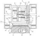
FIG. 2 is a schematic cross-sectional view of FIG. 1;
FIG. 3 is an enlarged view taken at A in FIG. 2;
fig. 4 is an enlarged view of fig. 2 at B.
Reference numbers in the figures: 1. a supporting bottom block; 2. connecting blocks; 3. a left mold; 4. a right mold; 5. a feed pipe; 6. a fixed block; 7. a circular spring; 8. a protective housing; 9. a limiting rod; 10. a second hook plate; 11. a movable block; 12. a groove; 13. a first hook plate; 14. a straight plate; 15. a moving block; 16. a vertical slot; 17. a transverse groove; 18. a gasket; 19. a travel bar; 20. a round table block; 21. a return spring; 22. a T-shaped limiting plate; 23. a buffer spring; 24. a round bar; 25. a Z-shaped groove; 26. a top rod; 27. mounting grooves; 28. a lifting rod; 29. an electric push rod; 30. an L-shaped oscillating lever.
Detailed Description
The technical solutions in the embodiments of the present invention will be described clearly and completely with reference to the accompanying drawings in the embodiments of the present invention, and it is obvious that the described embodiments are only some embodiments of the present invention, not all embodiments. Based on the embodiments in the present invention, all other embodiments obtained by a person skilled in the art without creative work belong to the protection scope of the present invention.
Referring to fig. 1-4, the present invention provides a technical solution: a mould with a decorative tube in asymmetric symmetrical design comprises a supporting bottom block 1, a left mould 3 and a right mould 4, wherein a vertical groove 16 is formed in the right side of the left mould 3, a transverse groove 17 is formed in the left side of the right mould 4, the left mould 3 is attached to the right mould 4, the vertical groove 16 is attached to the transverse groove 17 to form an L-shaped groove, a sealing gasket 18 is installed on the bottom of an inner cavity of the transverse groove 17, the sealing gasket 18 extends into the vertical groove 16, a feeding pipe 5 is fixedly connected to the position, close to the right side, of the top of the left mould 3, the feeding pipe 5 is communicated with the inside of the vertical groove 16, the bottoms of the left mould 3 and the right mould 4 are movably connected with the top of the supporting bottom block 1, a groove 12 is formed in the position, close to the left side, of the left mould 3, a movable block 11 is slidably connected to the groove 12, a buffer spring 23 is fixedly connected to the position, close to the top and the bottom, the left end of the buffer spring 23 is fixedly connected with the left inner wall of the groove 12, two ejector rods 26 are arranged on the right side of the movable block 11, a sealing pipe is sleeved outside the ejector rods 26, a through hole matched with the ejector rods 26 and the sealing pipe is formed in the inner wall of the right side of the groove 12 and communicated with the inside of the vertical groove 16, the ejector rods 26 and the sealing pipe extend into the through hole, a first hook plate 13 is movably connected to the center of the front wall of the movable block 11 through a rotating shaft and a bearing, a Z-shaped groove 25 is formed in the front wall of the first hook plate 13, a round rod 24 is sleeved on the position, close to the left side, of the Z-shaped groove 25, the rear wall of the round rod 24 is fixedly connected with the inner wall of the rear side of the groove 12, a second hook plate 10 is arranged below the first hook plate 13 and close to the right side, the rear wall of the second hook plate 10 is movably connected with the front wall of the right die 4 through a rotating shaft and a bearing, a round spring 7 is fixedly connected to the position, close to the right side, the bottom of the second hook plate 10, the bottom of the round spring 7 is fixedly connected with a fixed block 6, and the fixed block 6 is arranged on the front wall of the right die 4;
in the embodiment, through the mutual matching among the first hook plate 13, the second hook plate 10, the ejector rod 26 and other parts, the formed product can be ejected, so that the ejection mechanism is provided, and the effective demoulding of the product is realized;
the die comprises a bottom supporting block 1, a connecting block 2, circular grooves and mounting grooves 27, through grooves are communicated and connected between the circular grooves and the mounting grooves 27, circular table blocks 20 are arranged in the circular grooves, moving blocks 15 are arranged on the left side and the right side of the connecting block 2 respectively, a moving rod 19 is fixedly connected to one side, opposite to the connecting block 2, of each moving block 15, a through hole matched with the moving rod 19 is formed in the connecting block 2, the moving rod 19 moves relative to the connecting block 2 to penetrate through the through hole and extends into the circular groove to be attached to the side wall of each circular table block 20, a lifting rod 28 is fixedly connected to the bottom of each circular table block 20, the bottom end of each lifting rod 28 extends into the mounting groove 27, the front wall of each lifting rod 28 is movably connected with an L-shaped swinging rod 30 through a rotating shaft and a bearing, the rear wall of each L-shaped swinging rod 30 is movably connected with the inner wall of the rear side of each mounting groove 27 through the rotating shaft and the bearing, an electric push rod 29 is movably connected to the right side of each L-shaped swinging rod 30, the right side of each electric push rod 29 is hinged to the inner wall of the right-side of the electric push rod 29, the inner wall of the right-side mounting groove, the two straight plates 14 are fixedly connected to the top of the two straight plates, and the left-side-plate 14 of the left-side-fixed mould 14 and right-side-fixed mould 4 of the mould respectively connected to the mould 14;
in the embodiment, the electric push rod 29, the L-shaped oscillating rod 30, the lifting rod 28, the circular truncated cone block 20 and other components are matched with each other, so that the left die 3 and the right die 4 can be driven to move towards two sides or be attached to each other, the dies can be opened conveniently and rapidly, and the working efficiency can be effectively improved;
the protection device comprises a support bottom block 1, a protection shell 8, a slide block, reset springs 21, a limiting rod 9, a through hole and a positioning rod 9, wherein the protection shell 8 is fixedly connected to the positions, close to the top, of the left side and the right side of the support bottom block 1, one side, opposite to the support bottom block 1, of the protection shell 8 is provided with an opening, the positions, close to the top and the bottom, of the left side of a left die 3 and the right side of a right die 4 are fixedly connected with T-shaped limiting plates 22, the sides, far away from the two T-shaped limiting plates 22, located on the same side are provided with the slide block, the positions, close to the top and the bottom, of the inner wall of the protection shell 8 are fixedly connected with the reset springs 21, the other ends of the reset springs 21 are fixedly connected with the side walls of the T-shaped limiting plates 22, the limiting rod 9 is fixedly connected to the middle positions, on the left side of the left die 3 and the right side of the right die 4, and the through hole are provided with the through hole matched with the limiting rod 9;
in this embodiment, effective position limitation of the left mold 3 and the right mold 4 can be realized, which prevents the position deviation when the molds are opened, and at the same time, effective protection of the molds can be realized.
The working principle is as follows: when the technical scheme is used, firstly, raw materials are injected into the vertical groove 16 through the feeding pipe 5, the raw materials flow into the transverse groove 17, the vertical groove 16 and the transverse groove 17 form an L-shaped product, after cooling forming, the electric push rod 29 is started, the electric push rod 29 extends and drives the L-shaped oscillating rod 30 to rotate anticlockwise, the left side of the L-shaped oscillating rod 30 tilts downwards and pulls the lifting rod 28 to move downwards, the lifting rod 28 pulls the circular platform block 20 to move downwards, the circular platform block 20 extrudes the moving rods 19 on two sides, the two moving rods 19 drive the moving blocks 15 to move towards two sides, the two moving blocks 15 respectively drive the left die 3 and the right die 4 to move towards two sides through the two straight plates 14, the T-shaped limiting plate 22 extrudes the return spring 21, in the moving process of the left die 3 and the right die 4 towards two sides, the second hook plate 10 hooks the first hook plate 13 and drives the moving block 11 to move towards the right side, the moving block 11 drives the ejector rod 26 to move towards the right side and push out a formed finished product, when the circular rod 24 moves towards the Z-shaped groove 25, the right groove 24 and the second hook plate can drive the first hook plate to move towards the left die 4 and the left die to move in situ, and the second hook plate to push the second hook plate 23, and the left die to push the right die to push the second die to push rod 23, and the second die to push out, and push the second die, and the left die to push the second die to push rod 23, and push the die to push rod 23, and push the die to push out, and push the die to push out, and push the die.
Although embodiments of the present invention have been shown and described, it will be appreciated by those skilled in the art that various changes, modifications, substitutions and alterations can be made in these embodiments without departing from the principles and spirit of the invention, the scope of which is defined in the appended claims and their equivalents.
Claims (7)
1. The utility model provides a mould of asymmetric symmetric design of decorative pipe, is including supporting bottom piece (1), left mould (3) and right mould (4), its characterized in that: vertical groove (16) has been seted up on the right side of left mould (3), and transverse groove (17) has been seted up on the left side of right mould (4), left side mould (3) and right mould (4) laminate mutually, and erect groove (16) and transverse groove (17) and laminate and form the L-shaped groove, the top of left side mould (3) is close to right side department fixedly connected with inlet pipe (5), and inlet pipe (5) are linked together with the inside of erecting groove (16), the bottom of left side mould (3) and right mould (4) all with the top swing joint that supports bottom block (1), the antetheca that left side mould (3) is close to left side department sets up fluted (12), sliding connection has movable block (11) in recess (12), two ejector pin (26) are installed on the right side of movable block (11), and ejector pin (26) overcoat is equipped with sealed tube, set up on the right side inner wall of recess (12) with ejector pin (26) and sealed tube assorted through-hole, and through-hole and the inside that erects groove (16) are linked together to ejector pin (26) and sealed tube extend to the through-hole, the movable block (11) is equipped with the through-hole, the pivot (11) and the movable block (13) and the antetheca bearing block (13) and Z-shaped groove (25) is located through-axis bearing and Z hook plate (25) is close to the antetheca first axis (13), the rear wall of round bar (24) and the rear side inner wall fixed connection of recess (12), the below of first hook plate (13) is close to right side department and is provided with second hook plate (10), the back wall of second hook plate (10) is close to the antetheca swing joint of right side department through pivot and bearing and right mould (4), the bottom of second hook plate (10) is close to right side department fixedly connected with round spring (7), the bottom fixedly connected with fixed block (6) of round spring (7), and fixed block (6) are installed on the antetheca of right mould (4).
2. The mold of claim 1, wherein the mold comprises: the top of the supporting bottom block (1) is provided with a connecting block (2), the top of the connecting block (2) and the front wall of the supporting bottom block (1) are respectively provided with a circular groove and a mounting groove (27), a through groove is communicated and connected between the circular groove and the mounting groove (27), a circular table block (20) is arranged in the circular groove, moving blocks (15) are arranged on the left side and the right side of the connecting block (2), one side of each moving block (15) opposite to the connecting block (2) is fixedly connected with a moving rod (19), a through hole matched with the moving rod (19) is formed in the connecting block (2), the moving rod (19) moves relative to the connecting block (2) to penetrate through the through hole and extends into the circular groove to be attached to the side wall of the circular table block (20), the bottom of the circular table block (20) is fixedly connected with a lifting rod (28), the bottom end of the lifting rod (28) extends into the mounting groove (27), the front wall of the lifting rod (28) is movably connected with an L-shaped swinging rod (30) through a rotating shaft and a bearing, the right end of the L-shaped swinging rod (30) is movably connected with a bearing, the rear wall of the L-shaped swinging rod (30) and the rear wall of the L-shaped swinging rod (30) is connected with the inner wall of the bearing through the movable shaft and the movable shaft (29), the movable shaft and the two electric push rods (29) are hinged to the two straight push rods (14) on the inner wall of the movable push rod (29) near the inner wall of the mounting groove (27), the tops of the two straight plates (14) are respectively and fixedly connected with the bottoms of the left die (3) and the right die (4).
3. The mold of claim 1, wherein the mold comprises: the left side of movable block (11) is close to top and bottom department fixedly connected with buffer spring (23), and the left end of buffer spring (23) and the left side inner wall fixed connection of recess (12).
4. The mold of claim 1, wherein the mold comprises: and a sealing gasket (18) is arranged at the bottom of the inner cavity of the transverse groove (17), and the sealing gasket (18) extends into the vertical groove (16).
5. The mold of claim 1, wherein the mold comprises: the left and right sides that supports end block (1) is close to top department equal fixedly connected with protective housing (8), and protective housing (8) and support one side that end block (1) is relative and set up for the opening, the left side of left side mould (3) and the right side of right mould (4) are close to top and the equal fixedly connected with T of bottom department limiting plate (22), lie in two with one side the inner chamber top and the bottom sliding connection of one side and protective housing (8) that T shape limiting plate (22) kept away from mutually.
6. The mold of claim 5, wherein the mold comprises: the inner wall of protective housing (8) is close to top and the equal fixedly connected with reset spring (21) of bottom department, and the other end of reset spring (21) and the lateral wall fixed connection of T shape limiting plate (22), locate equal fixedly connected with gag lever post (9) in the middle of the left side of left side mould (3) and the right side of right mould (4), seted up on the lateral wall of protective housing (8) with gag lever post (9) assorted through-hole.
7. The mold of claim 5, wherein the mold comprises: the slide blocks are arranged on two sides, located on the same side, of the T-shaped limiting plates (22) far away from each other, and slide grooves matched with the slide blocks are formed in the top and the bottom of the inner cavity of the protective shell (8).
Priority Applications (1)
| Application Number | Priority Date | Filing Date | Title |
|---|---|---|---|
| CN202222588940.XU CN218462817U (en) | 2022-09-29 | 2022-09-29 | Mould of asymmetric symmetrical design of decorative pipe |
Applications Claiming Priority (1)
| Application Number | Priority Date | Filing Date | Title |
|---|---|---|---|
| CN202222588940.XU CN218462817U (en) | 2022-09-29 | 2022-09-29 | Mould of asymmetric symmetrical design of decorative pipe |
Publications (1)
| Publication Number | Publication Date |
|---|---|
| CN218462817U true CN218462817U (en) | 2023-02-10 |
Family
ID=85143715
Family Applications (1)
| Application Number | Title | Priority Date | Filing Date |
|---|---|---|---|
| CN202222588940.XU Expired - Fee Related CN218462817U (en) | 2022-09-29 | 2022-09-29 | Mould of asymmetric symmetrical design of decorative pipe |
Country Status (1)
| Country | Link |
|---|---|
| CN (1) | CN218462817U (en) |
Cited By (1)
| Publication number | Priority date | Publication date | Assignee | Title |
|---|---|---|---|---|
| CN118144223A (en) * | 2024-04-02 | 2024-06-07 | 东莞市南炬高分子材料有限公司 | Silica gel forming device |
-
2022
- 2022-09-29 CN CN202222588940.XU patent/CN218462817U/en not_active Expired - Fee Related
Cited By (1)
| Publication number | Priority date | Publication date | Assignee | Title |
|---|---|---|---|---|
| CN118144223A (en) * | 2024-04-02 | 2024-06-07 | 东莞市南炬高分子材料有限公司 | Silica gel forming device |
Similar Documents
| Publication | Publication Date | Title |
|---|---|---|
| CN218462817U (en) | Mould of asymmetric symmetrical design of decorative pipe | |
| CN210877407U (en) | Automobile water channel forming die | |
| CN113103520B (en) | Precise injection mold convenient for material taking | |
| CN217494972U (en) | Waterproof lamp shade integral type injection mold of car | |
| CN213055848U (en) | Ejecting flip-chip injection mold structure | |
| CN211074681U (en) | Plastic suction mold with quick mold removing function | |
| CN209920613U (en) | Mechanical material preparation mould | |
| CN210791932U (en) | Conveniently-disassembled plastic mold | |
| CN211868468U (en) | Mold convenient for material taking | |
| CN209851469U (en) | Injection mold for processing refrigerator drawer face mask with complex structure | |
| CN220261875U (en) | Precise die injection molding and separating equipment | |
| CN220837822U (en) | Molybdenum alloy slab forming die | |
| CN111361085A (en) | Double-layer die machining equipment | |
| CN216263411U (en) | Die casting die of pot under coffee pot | |
| CN216461686U (en) | New energy automobile controller box die-casting mould | |
| CN215614959U (en) | Processing die for copper ornament | |
| CN213617934U (en) | Glasses packing carton device of moulding plastics with demoulding structure of being convenient for | |
| CN218053943U (en) | Thermal forming die capable of accurately closing die | |
| CN218462793U (en) | Injection mold structure with high demolding efficiency | |
| CN212372372U (en) | Wicker bending and shaping equipment | |
| CN219988323U (en) | Core pulling structure of injection mold | |
| CN215472466U (en) | Mould with self-locking function and ejection mechanism | |
| CN213559746U (en) | Vertical modeling control system for kitchen ware casting | |
| CN217968196U (en) | Core-pulling structure of toilet drainage seat | |
| CN221291999U (en) | Combined shaping die |
Legal Events
| Date | Code | Title | Description |
|---|---|---|---|
| GR01 | Patent grant | ||
| GR01 | Patent grant | ||
| CF01 | Termination of patent right due to non-payment of annual fee | ||
| CF01 | Termination of patent right due to non-payment of annual fee |
Granted publication date: 20230210 |