CN218403427U - Tower machine standard festival convenient to transportation dismouting - Google Patents
Tower machine standard festival convenient to transportation dismouting Download PDFInfo
- Publication number
- CN218403427U CN218403427U CN202222596518.9U CN202222596518U CN218403427U CN 218403427 U CN218403427 U CN 218403427U CN 202222596518 U CN202222596518 U CN 202222596518U CN 218403427 U CN218403427 U CN 218403427U
- Authority
- CN
- China
- Prior art keywords
- connecting rod
- bracing piece
- bolt
- movable block
- pole setting
- Prior art date
- Legal status (The legal status is an assumption and is not a legal conclusion. Google has not performed a legal analysis and makes no representation as to the accuracy of the status listed.)
- Active
Links
Images


Abstract
The utility model belongs to the technical field of tower crane equipment, and a tower machine standard festival convenient to transportation dismouting is disclosed, including connecting rod one, the right side swing joint of connecting rod one has connecting rod two, the left side fixed mounting of connecting rod two has the fixed block. The utility model discloses a set up the fixed block, movable block and dog, when operating personnel swivelling joint bolt is short-term, make to remove the fixed to connecting rod one, and then unpack connecting rod two and connecting rod one apart each other, and then swivelling joint bolt two, make to remove the fixed to the movable block, make to move aside the movable block from the bracing piece outer surface, make it remove the contact to the dog, and unpack bracing piece two and movable block apart, thereby be convenient for operating personnel to disassemble the inside longer pole of tower machine standard festival, make and reduce area occupied, and then be convenient for transport it, the use of giving operating personnel has brought the facility.
Description
Technical Field
The utility model belongs to the technical field of tower crane equipment, specifically a tower machine standard festival convenient to transportation dismouting.
Background
At present, operating personnel is when handling the construction, often need use tower machine standard festival, make the work efficiency who improves the tower machine, and tower machine standard festival among the prior art is at the in-process of in-service use, although can realize basic bearing effect, simultaneously when using, generally connect connecting rod and installation pole through the bolt, make and be convenient for dismantle it, and then when transporting the pole that the tower machine standard festival was dismantled, its inside has longer bracing piece and connecting rod, make other poles of far exceeding, thereby make the area occupied increase, make the transportation comparatively inconvenient, make it need transport many times, inconvenience has been brought for operating personnel's use, consequently, need improve it.
SUMMERY OF THE UTILITY MODEL
The utility model aims at the above problem, the utility model provides a tower machine standard festival convenient to transportation dismouting has the advantage of being convenient for transport.
In order to achieve the above purpose, the utility model provides a following technical scheme: the utility model provides a tower machine standard festival convenient to transportation dismouting, includes connecting rod one, the right side swing joint of connecting rod one has connecting rod two, the left side fixed mounting of connecting rod two has the fixed block, the surface of fixed block cup joints with the surface activity of connecting rod one, connecting bolt one has been cup jointed to the positive screw thread of fixed block, the back of connecting bolt one runs through fixed block and connecting rod respectively and extends to inside one connecting rod in the lump, the inboard equal movable mounting of connecting rod one and connecting rod two has the installation pole, the both ends of installation pole run through connecting rod one respectively and connecting rod two and extend to inside one connecting rod one and connecting rod two, the both ends of installation pole run through connecting rod one respectively, connecting rod two and installation pole and extend to inside the installation pole, the surface activity of pole setting has cup jointed bracing piece one and bracing piece two respectively, the other end of bracing piece one and the other end activity joint of bracing piece two, the surface activity of bracing piece one has cup jointed the movable block, the outer surface activity of movable block and the outer surface activity of bracing piece two, the positive both sides of movable block cup joint equal screw thread joint bolt two, the bracing piece respectively and extend to inside one and two bracing pieces.
As the utility model discloses it is preferred, the external fixed surface of bracing piece two has cup jointed the dog that is located the movable block right side, the left side of dog and the right side swing joint of movable block.
As the utility model discloses it is preferred, the equal movable mounting in positive top of connecting rod one and connecting rod two has the mounting bracket, mounting bolt one has been cup jointed to the positive screw thread of mounting bracket, inside the back of mounting bolt one runs through connecting rod one, mounting bracket and connecting rod two respectively and extends to connecting rod one and connecting rod two.
As the utility model discloses it is preferred, the equal fixed mounting in top of connecting rod one, connecting rod two and installation pole has stopper one, the outside screw thread of stopper one has cup jointed chucking bolt one, the other end of chucking bolt one runs through stopper one respectively and the pole setting extends to inside the pole setting.
As the utility model discloses it is preferred, the equal fixed mounting in upper and lower place of pole setting surface has stopper two, the surface of stopper two and the surface swing joint of connecting rod one and connecting rod two, the outside screw thread of stopper two has cup jointed chucking bolt two, the other end of chucking bolt two runs through stopper two, connecting rod one, connecting rod two, installation pole and pole setting respectively and extends to inside installation pole and the pole setting.
As the utility model discloses it is preferred, bracing piece one and bracing piece two the equal screw thread in front have cup jointed mounting bolt two, mounting bolt two's the other end runs through bracing piece one, bracing piece two and pole setting and extends to inside the pole setting.
Compared with the prior art, the beneficial effects of the utility model are as follows:
1. the utility model discloses a set up the fixed block, movable block and dog, when operating personnel swivelling joint bolt is one hour, make to remove the fixed to connecting rod one, and then unpack connecting rod two and connecting rod one each other apart, and then swivelling joint bolt two, make to remove the fixed to the movable block, make to move aside the movable block from the bracing piece external surface, make it remove the contact to the dog, and unpack bracing piece two and movable block apart, thereby be convenient for operating personnel to disassemble the inside longer pole of tower machine standard festival, make and reduce area occupied, and then be convenient for transport it, the use of giving operating personnel has brought the facility.
2. The utility model discloses a set up the pole setting, stopper one and stopper two, insert respectively to connecting rod one and two inside connecting rod when operating personnel with the connecting rod two, and then insert the pole setting to connecting rod one from the top of connecting rod one and connecting rod two, inside connecting rod two and the installation pole, simultaneously because the design of stopper one, will carry on spacingly to the pole setting, make and prevent to incline to the inboard, and because the design of stopper two, make and prevent that the pole setting from leaning out, thereby be convenient for operating personnel installs chucking bolt one and chucking bolt two, make and be convenient for assemble tower machine standard festival, the use of giving operating personnel has brought the facility.
Drawings
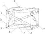
FIG. 1 is a schematic view of the present invention;
FIG. 2 is a front sectional view of the present invention;
FIG. 3 is a schematic side sectional view of the present invention;
FIG. 4 is a schematic view of a portion of the enlarged structure at A in FIG. 2;
fig. 5 is a partially enlarged structural view at B in fig. 3.
In the figure: 1. a first connecting rod; 2. a second connecting rod; 3. a fixed block; 4. connecting a first bolt; 5. mounting a rod; 6. erecting a rod; 7. a first supporting rod; 8. a second supporting rod; 9. a movable block; 10. a second connecting bolt; 11. a stopper; 12. a mounting frame; 13. mounting a first bolt; 14. a first limiting block; 15. clamping the first bolt; 16. a second limiting block; 17. a second clamping bolt; 18. and mounting a second bolt.
Detailed Description
The technical solutions in the embodiments of the present invention will be described clearly and completely with reference to the accompanying drawings in the embodiments of the present invention, and it is obvious that the described embodiments are only some embodiments of the present invention, not all embodiments. Based on the embodiments in the present invention, all other embodiments obtained by a person skilled in the art without creative work belong to the protection scope of the present invention.
As shown in fig. 1 to 5, the utility model provides a tower machine standard festival convenient to transportation dismouting, including connecting rod 1, the right side swing joint of connecting rod 1 has connecting rod two 2, the left side fixed mounting of connecting rod two 2 has fixed block 3, the surface of fixed block 3 cup joints with the surface activity of connecting rod 1, connecting bolt one 4 has been cup jointed to the positive screw thread of fixed block 3, the back of connecting bolt one 4 runs through fixed block 3 and connecting rod one 1 respectively and extends to connecting rod one 1 inside, the inboard equal movable mounting of connecting rod one 1 and connecting rod two 2 has installation pole 5, the both ends of installation pole 5 run through connecting rod one 1 respectively and connecting rod two 2 and extend to connecting rod one 1 and connecting rod two 2 inside, the equal swing joint in top of connecting rod one 1 and connecting rod two 2 has pole setting 6, the both ends of pole setting 6 run through connecting rod one 1 respectively, connecting rod two 2 and installation pole 5 extend to inside the installation pole 5, the surface of pole setting 6 activity has cup jointed one 7 and two 8 respectively, the other end of bracing piece and the other end activity joint of bracing piece 7, the bracing piece 9 and the both sides of the movable block 9 and two movable joint of bracing piece respectively, the movable block and two movable block 8 and the both sides of bracing piece are connected bolt piece are connected to the front of the movable block 9, the movable block and the movable block of bracing piece 10 and two piece is connected.
When an operator rotates the first connecting bolt 4, the first connecting bolt 4 is moved out of the first connecting rod 1, the first connecting rod 1 is enabled to be fixed, the second connecting rod 2 is convenient to move away from the right side of the first connecting rod 1, meanwhile, the second connecting bolt 10 is rotated, the second connecting bolt 10 is moved out of the first supporting rod 7 and the second supporting rod 8, the first connecting bolt is enabled to be fixed to the movable block 9, the second supporting rod 8 is moved out of the movable block 9, the movable block 9 is pulled, the movable block 9 is enabled to be moved to the outer surface of the first supporting rod 7, meanwhile, the second connecting bolt 10 on the right side is rotated, the second connecting bolt is screwed into the first supporting rod 7, the first supporting rod 7 is enabled to be fixed to the movable block 9, the operator can detach a long rod inside a standard section of the tower crane conveniently, occupied area is reduced, transportation is facilitated, and convenience is brought to the use of the operator.
Referring to fig. 1, a stopper 11 located on the right side of the movable block 9 is fixedly sleeved on the outer surface of the second support rod 8, and the left side of the stopper 11 is movably connected with the right side of the movable block 9.
As the utility model discloses a technical optimization scheme, through the design of dog 11, will be convenient for operating personnel when fixing bracing piece 7 and bracing piece two 8 for block the movable block 9 through dog 11, and then be convenient for with two 10 screw in of connecting bolt to the bracing piece two 8 insides on right side, make to be convenient for install.
Referring to fig. 1, the top of the front of the first connecting rod 1 and the top of the front of the second connecting rod 2 are both movably provided with a mounting frame 12, the front of the mounting frame 12 is in threaded sleeve connection with a first mounting bolt 13, and the back of the first mounting bolt 13 respectively penetrates through the first connecting rod 1, the mounting frame 12 and the second connecting rod 2 and extends into the first connecting rod 1 and the second connecting rod 2.
As a technical optimization scheme of the utility model, through the design of mounting bracket 12, the operating personnel of will being convenient for installs two tower machine standard festivals, and the use of giving operating personnel has brought the facility, because the design of a mounting bolt 13 will be convenient for install it simultaneously.
Referring to fig. 4 and 5, a first limiting block 14 is fixedly mounted at the tops of the first connecting rod 1, the second connecting rod 2 and the mounting rod 5, a first clamping bolt 15 is sleeved on the outer thread of the first limiting block 14, and the other end of the first clamping bolt 15 penetrates through the first limiting block 14 and the vertical rod 6 respectively and extends to the inside of the vertical rod 6.
As the utility model discloses a technical optimization scheme, through the design of stopper 14, will be when counter rod 6 is installed, when will installing counter rod 6 through stopper 14 for prevent to take place the slope, thereby be convenient for screw chucking bolt 15, make the operating personnel of being convenient for install tower machine standard festival.
Referring to fig. 4 and 5, a second limiting block 16 is fixedly mounted above and below the outer surface of the vertical rod 6, the outer surface of the second limiting block 16 is movably connected with the outer surfaces of the first connecting rod 1 and the second connecting rod 2, a second clamping bolt 17 is sleeved on the outer thread of the second limiting block 16, and the other end of the second clamping bolt 17 penetrates through the second limiting block 16, the first connecting rod 1, the second connecting rod 2, the mounting rod 5 and the vertical rod 6 respectively and extends to the inside of the mounting rod 5 and the vertical rod 6.
As the utility model discloses a technical optimization scheme, through the design of stopper two 16, will carry on spacingly through stopper two 16 to pole setting 6 for prevent to incline, thereby be convenient for fix pole setting 6, connecting rod 1, connecting rod two 2 and installation pole 5, brought the facility for operating personnel's installation.
Referring to fig. 1, the front surfaces of the first supporting rod 7 and the second supporting rod 8 are respectively sleeved with a second mounting bolt 18 through threads, and the other end of the second mounting bolt 18 penetrates through the first supporting rod 7, the second supporting rod 8 and the vertical rod 6 and extends into the vertical rod 6.
As the utility model discloses a technical optimization scheme, when rotating two 18 installation bolts through operating personnel, will make two 18 installation bolts follow 6 inside shifting out of pole setting, make it remove the fixed to bracing piece 7 and two 8 bracing pieces to be convenient for dismantle it.
The utility model discloses a theory of operation and use flow:
firstly, when an operator dismantles a standard section of a tower crane, the first limiting block 14 and the second clamping bolt 17 are sequentially rotated at the moment, so that the fixation of the first connecting rod 1, the second connecting rod 2, the mounting rod 5 and the vertical rod 6 is released, the first connecting rod 1, the second connecting rod 2 and the mounting rod 5 are further dismantled from the two ends of the vertical rod 6, the first connecting bolt 4 is rotated, the first connecting bolt 4 is moved out from the inside of the first connecting rod 1, so that the fixation of the first connecting rod 1 is released, the second connecting rod 2 is convenient to move away from the right side of the first connecting rod 1, the second connecting bolt 10 is rotated, the second connecting bolt 10 is respectively moved out from the insides of the first supporting rod 7 and the second supporting rod 8, so that the fixing of the movable block 9 is released, the movable block 9 is pulled later, so that the movable block 9 is moved out from the outside of the second supporting rod 8, the contact with the stop block 11 is released, the second connecting bolt 10 on the right side is rotated, the second connecting bolt 10 is screwed into the insides of the first supporting rod 7, so that the movable block 9 is fixed, meanwhile, the second supporting rod 8 and the first supporting rod 7 and the tower crane is convenient to dismantle of the standard section, so that the transport efficiency of the operator is improved, and the use efficiency of the operator is improved.
Then, when the operating personnel is assembling the tower crane standard knot after the dismantlement, this moment, assemble connecting rod one 1 and connecting rod two 2, make connecting rod two 2 insert respectively to connecting rod one 1 and connecting rod two 2 inside, insert connecting rod one 1 from the top of connecting rod one 1 and connecting rod two 2 respectively with pole setting 6 simultaneously, connecting rod two 2 and installation pole 5 inside, make and form a support, and because the design of stopper one 14, will carry out spacing to pole setting 6, make and prevent to incline to the inboard, later because the design of stopper two 16, make and prevent pole setting 6 to incline to the outboard, then rotate chucking bolt one 15 and chucking bolt two 17 in proper order, make and install connecting rod one 1, connecting rod two 2, installation pole 5 and pole setting 6, and then assemble bracing piece one 7 and bracing piece two 8, make and cover bracing piece one 7 and bracing piece two 8 assembled on 6 surface, rotatory installation bolt two 18 simultaneously, make and fix bracing piece one 7 and bracing piece two 8, then bring connecting rod one 1, connecting rod two 2 and installation pole 5 at the top of pole setting 6 to be convenient for the operating personnel to assemble the tower crane, thereby the operating personnel has carried out convenient use.
It should be noted that, in this document, relational terms such as first and second, and the like are used solely to distinguish one entity or action from another entity or action without necessarily requiring or implying any actual such relationship or order between such entities or actions. Also, the terms "comprises," "comprising," or any other variation thereof, are intended to cover a non-exclusive inclusion, such that a process, method, article, or apparatus that comprises a list of elements does not include only those elements but may include other elements not expressly listed or inherent to such process, method, article, or apparatus.
Although embodiments of the present invention have been shown and described, it will be appreciated by those skilled in the art that changes, modifications, substitutions and alterations can be made in these embodiments without departing from the principles and spirit of the invention, the scope of which is defined in the appended claims and their equivalents.
Claims (6)
1. The utility model provides a tower machine standard festival convenient to transportation dismouting, includes connecting rod one (1), its characterized in that: the right side swing joint of connecting rod one (1) has connecting rod two (2), the left side fixed mounting of connecting rod two (2) has fixed block (3), the surface of fixed block (3) cup joints with the surface activity of connecting rod one (1), the front screw thread of fixed block (3) has cup jointed connecting bolt one (4), the back of connecting bolt one (4) runs through fixed block (3) and connecting rod one (1) respectively and extends to connecting rod one (1) inside, the equal movable mounting in inboard of connecting rod one (1) and connecting rod two (2) has installation pole (5), the both ends of installation pole (5) run through connecting rod one (1) respectively and connecting rod two (2) and extend to connecting rod one (1) and connecting rod two (2) inside, the equal movable connection in top of connecting rod one (1) and connecting rod two (2) has pole setting (6), the both ends of pole setting (6) run through connecting rod one (1), connecting rod two (2) and installation pole (5) respectively and extend to installation pole setting pole (5) inside, the bracing piece (7) of bracing piece activity joint has one (7) respectively, the other end activity piece (7) and the other end of bracing piece (7), the inner wall of movable block (9) cup joints with the surface activity of bracing piece two (8), connecting bolt two (10) have been cup jointed to the equal screw thread in both sides that movable block (9) is positive, the back of connecting bolt two (10) runs through movable block (9), bracing piece one (7) and bracing piece two (8) respectively and extends to bracing piece one (7) and bracing piece two (8) inside.
2. The tower crane standard knot convenient to transport dismouting of claim 1, its characterized in that: the outer fixed surface of bracing piece two (8) has cup jointed dog (11) that are located movable block (9) right side, the left side of dog (11) and the right side swing joint of movable block (9).
3. The tower crane standard knot convenient to transport, disassemble and assemble of claim 1 is characterized in that: the equal movable mounting in top that connecting rod (1) and connecting rod two (2) are positive has mounting bracket (12), mounting bolt (13) have been cup jointed to the front screw thread of mounting bracket (12), the back of mounting bolt (13) runs through connecting rod (1), mounting bracket (12) and connecting rod two (2) respectively and extends to connecting rod (1) and connecting rod two (2) inside.
4. The tower crane standard knot convenient to transport dismouting of claim 1, its characterized in that: the equal fixed mounting in top of connecting rod (1), connecting rod two (2) and installation pole (5) has stopper (14), the outside screw thread of stopper (14) has cup jointed chucking bolt (15), the other end of chucking bolt (15) runs through stopper (14) and pole setting (6) respectively and extends to inside pole setting (6).
5. The tower crane standard knot convenient to transport, disassemble and assemble of claim 1 is characterized in that: equal fixed mounting in the upper and lower side of pole setting (6) surface has stopper two (16), the surface of stopper two (16) and the surface swing joint of connecting rod (1) and connecting rod two (2), the outside screw thread of stopper two (16) has cup jointed chucking bolt two (17), the other end of chucking bolt two (17) runs through stopper two (16), connecting rod (1), connecting rod two (2), installation pole (5) and pole setting (6) respectively and extends to installation pole (5) and pole setting (6) inside.
6. The tower crane standard knot convenient to transport dismouting of claim 1, its characterized in that: the equal screw thread in front of bracing piece (7) and bracing piece two (8) has cup jointed construction bolt two (18), the other end of construction bolt two (18) runs through bracing piece (7), bracing piece two (8) and pole setting (6) and extends to inside pole setting (6).
Priority Applications (1)
| Application Number | Priority Date | Filing Date | Title |
|---|---|---|---|
| CN202222596518.9U CN218403427U (en) | 2022-09-29 | 2022-09-29 | Tower machine standard festival convenient to transportation dismouting |
Applications Claiming Priority (1)
| Application Number | Priority Date | Filing Date | Title |
|---|---|---|---|
| CN202222596518.9U CN218403427U (en) | 2022-09-29 | 2022-09-29 | Tower machine standard festival convenient to transportation dismouting |
Publications (1)
| Publication Number | Publication Date |
|---|---|
| CN218403427U true CN218403427U (en) | 2023-01-31 |
Family
ID=84998417
Family Applications (1)
| Application Number | Title | Priority Date | Filing Date |
|---|---|---|---|
| CN202222596518.9U Active CN218403427U (en) | 2022-09-29 | 2022-09-29 | Tower machine standard festival convenient to transportation dismouting |
Country Status (1)
| Country | Link |
|---|---|
| CN (1) | CN218403427U (en) |
-
2022
- 2022-09-29 CN CN202222596518.9U patent/CN218403427U/en active Active
Similar Documents
| Publication | Publication Date | Title |
|---|---|---|
| CN211541002U (en) | Assembly jig is used in processing of large-scale steel construction | |
| CN208976458U (en) | A kind of bucket tool cleaning device for building | |
| CN218403427U (en) | Tower machine standard festival convenient to transportation dismouting | |
| CN211873066U (en) | Supporting structure of steel bar supporting framework | |
| CN208782762U (en) | The photovoltaic bracket of adjustable-angle | |
| CN212406037U (en) | Assembly type building external hanging rack | |
| CN210289098U (en) | Novel building support supports buckle | |
| CN213597205U (en) | Light steel structure frame | |
| CN208103605U (en) | A kind of multi-functional copper-clad aluminum conductor winding wire-unfolding rack | |
| CN220851563U (en) | Assembled steel scattering support frame | |
| CN210976518U (en) | Adjustable building frame for house construction project | |
| CN217897331U (en) | Temporary fixing device for installation of large-span steel structure | |
| CN219034266U (en) | Novel tent support pole | |
| CN216552960U (en) | Scaffold frame for building repair convenient to dismantle installation | |
| CN219451254U (en) | Novel energy-saving heat-insulation sandwich board | |
| CN219012174U (en) | Novel stainless steel net frame structure | |
| CN205351837U (en) | Supporting device for heat collection tube | |
| CN217871760U (en) | Scaffold connecting piece convenient to dismouting | |
| CN219471593U (en) | Connecting beam installation device | |
| CN213547423U (en) | Photovoltaic support convenient to equipment | |
| CN215692771U (en) | Dust collector for environmental engineering | |
| CN214154395U (en) | Solar panel convenient to loading and unloading | |
| CN212412689U (en) | Pipeline erecting device for assembled wall | |
| CN211321052U (en) | Energy-saving environment-friendly motor with installation base | |
| CN209660906U (en) | A kind of board-like water trough cabinet of dump bottom |
Legal Events
| Date | Code | Title | Description |
|---|---|---|---|
| GR01 | Patent grant | ||
| GR01 | Patent grant |