CN218398810U - Cement agitating unit for building engineering - Google Patents
Cement agitating unit for building engineering Download PDFInfo
- Publication number
- CN218398810U CN218398810U CN202222718457.9U CN202222718457U CN218398810U CN 218398810 U CN218398810 U CN 218398810U CN 202222718457 U CN202222718457 U CN 202222718457U CN 218398810 U CN218398810 U CN 218398810U
- Authority
- CN
- China
- Prior art keywords
- churn
- mixing drum
- gear
- cement
- rod
- Prior art date
- Legal status (The legal status is an assumption and is not a legal conclusion. Google has not performed a legal analysis and makes no representation as to the accuracy of the status listed.)
- Active
Links
Images



Landscapes
- Mixers Of The Rotary Stirring Type (AREA)
Abstract
The utility model relates to a cement agitating unit for building engineering, including bottom plate and churn, both sides department above the bottom plate all is connected with the backup pad, two be provided with the churn between the backup pad, the both sides of department all are connected with the bull stick in the middle of the churn, two the one end that the churn was kept away from to the bull stick is rotatable setting respectively in two backup pads, the bottom of churn is changeed tightly and is had the bottom, department injects first montant in the middle of above the churn, first montant injects and is provided with a plurality of stirring leaves on the part in the churn, the top of churn is provided with the overhead tank, and step motor drives churn pivoted in-process, drives horizontal pole one end and rotates in the ring upper groove, utilizes the third gear of horizontal pole one end to roll on the tooth of recess cell wall, can drive first montant and stirring leaf at the churn internal rotation automatically, stirs cement, and simple structure, low in manufacturing cost, the noise that produces when having reduced cement stirring.
Description
Technical Field
The application relates to the technical field of cement stirring, in particular to a cement stirring device for constructional engineering.
Background
During construction engineering construction, a large amount of cement needs to be used, when the cement is used, water needs to be added for stirring, and a cement stirring device is used for automatically stirring the cement, so that the cement stirring efficiency is higher compared with manual stirring;
at present, a utility model patent with the patent number of CN216465351U discloses a cement stirring device for building engineering construction, which enables a stirring cylinder to have better stirring effect and higher stirring efficiency under the assistance of a stirring motor, a stirring shaft and stirring blades in the process of overturning and stirring materials through a stepping motor, a driving wheel, a belt, a driven wheel, a rotating shaft, a first connecting shaft, a second connecting shaft, a first supporting plate and a second supporting plate, and solves the problems of poor effect of stirring materials such as cement and the like and low material stirring efficiency of the existing cement stirring device;
however, the rotation of the mixing drum, the rotation of the mixing shaft and the mixing blades of the device need to be driven by the stepping motor and the mixing motor respectively to rotate, so that the manufacturing cost is increased, and in the cement mixing process, the noise is increased, so that the improvement is needed.
SUMMERY OF THE UTILITY MODEL
In order to solve the problems proposed in the background art described above, the present application provides a cement stirring device for construction engineering.
The application provides a cement agitating unit for building engineering adopts following technical scheme:
a cement stirring device for constructional engineering comprises a bottom plate and a stirring cylinder, wherein two supporting plates are connected to two sides of the upper surface of the bottom plate, the stirring cylinder is arranged between the two supporting plates, rotating rods are connected to two sides of the middle of the stirring cylinder, one ends of the two rotating rods, which are far away from the stirring cylinder, are respectively and rotatably arranged on the two supporting plates, the bottom end of the stirring cylinder is tightly rotated and provided with a bottom cover, a first vertical rod is inserted into the middle of the upper surface of the stirring cylinder, a plurality of stirring blades are arranged on the part of the first vertical rod inserted into the stirring cylinder, a top box is arranged at the top end of the stirring cylinder, the top end of the first vertical rod inserted into the top box is sleeved with a first bevel gear, the top box is transversely inserted with a cross rod, one end of the cross rod inserted into the top box is sleeved with a second bevel gear, the first bevel gear and the second bevel gear are in meshed connection, the top end of one support plate is connected with a connecting rod, the one end of connecting rod is provided with the ring, set up the recess on the side of one side that the ring is close to the churn, the other end of horizontal pole injects in the recess, the cover has the third gear on the one end that the horizontal pole injects in the recess, be provided with the tooth of being connected with the meshing of third gear on the cell wall of recess.
Preferably, the inner wall of the mixing drum is provided with a scraping ring which can move up and down, and the upper side and the lower side of the inner wall of the scraping ring are both obliquely arranged towards the middle.
Preferably, a reciprocating screw rod is inserted into the edge of the stirring cylinder, a threaded sleeve is sleeved on the reciprocating screw rod, a fixed rod is connected onto the threaded sleeve, and one end of the fixed rod is connected onto the inner wall of the scraping ring.
Preferably, a first gear is sleeved on the part, inserted into the top box, of the first vertical rod, a second vertical rod is inserted into the edge of the top box, a second gear is sleeved on the part, inserted into the top box, of the second vertical rod, the first gear is in meshed connection with the second gear, and the bottom end of the second vertical rod is connected with the top end of the reciprocating screw rod.
Preferably, a stepping motor is installed at the edge of the upper surface of the bottom plate, belt pulleys are sleeved on an output shaft of the stepping motor and the end part of one rotating rod, and a belt is sleeved between the two belt pulleys.
To sum up, the application comprises the following beneficial technical effects:
1. the utility model discloses be provided with the churn between two backup pads on the bottom plate, some both sides department in the middle of the churn all is connected with the bull stick, one of them bull stick and step motor output shaft all overlap has the belt pulley, the cover has the belt between two belt pulleys, horizontal pole has been injected in the churn top roof box, the second bevel gear of horizontal pole one end and the first montant top first bevel gear of injecting in the churn mesh and be connected, the part that first montant injects in the churn is provided with the stirring leaf, wherein a backup pad top is connected with the ring through the connecting rod, horizontal pole one end injects in the recess on the ring, mesh and be connected between the third gear of horizontal pole one end and the tooth on the recess cell wall, in the process that the step motor is started to drive the churn rotation like this, drive horizontal pole one end and rotate in the recess on the ring, utilize the third gear of horizontal pole one end to roll on the tooth of recess cell wall, can drive first montant and stirring leaf automatically and rotate in the churn, stir cement, simple structure, low in manufacturing cost, the noise that produces when having reduced cement stirring;
2. a reciprocating screw rod is inserted into the mixing drum, a scraping ring is arranged on the inner wall of the mixing drum, a threaded sleeve is arranged at one end of a fixed rod on the inner wall of the scraping ring and sleeved on the reciprocating screw rod, and the threaded sleeve drives the scraping ring to cling to the inner wall of the mixing drum to move up and down by utilizing the rotation of the reciprocating screw rod so as to clean cement bonded on the inner wall of the mixing drum and enable the cement to be more thorough during discharging; the top of reciprocal lead screw is connected with the second montant, and the cover has the second gear on the top that the second montant injects the top incasement, and the meshing is connected between the first gear on second gear and the first montant, and first montant drives the stirring leaf and rotates when stirring cement like this, drives reciprocal lead screw and rotates, and then realizes scraping the clearance work of circle to the churn inner wall automatically.
Drawings
FIG. 1 is a schematic structural diagram of a cement mixing device for construction engineering in an embodiment of the present application;
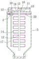
FIG. 2 is a sectional view of the inner structure of a mixing drum of a cement mixing device for construction engineering in the embodiment of the present application;
FIG. 3 is an enlarged view of the structure A in FIG. 2 of a cement mixing device for construction engineering in an embodiment of the present application;
fig. 4 is a schematic structural diagram of a circular ring of a cement stirring device for constructional engineering in an embodiment of the application.
Description of reference numerals: 1. a base plate; 2. a support plate; 3. a mixing drum; 4. a rotating rod; 5. a stepping motor; 6. a pulley; 7. a belt; 8. a circular ring; 9. a connecting rod; 10. a top box; 11. a cross bar; 12. a first vertical bar; 13. a second vertical bar; 14. stirring blades; 15. a first bevel gear; 16. a second bevel gear; 17. a reciprocating screw rod; 18. a first gear; 19. a second gear; 20. scraping a ring; 21. fixing the rod; 22. a threaded sleeve; 23. a groove; 24. a third gear.
Detailed Description
The present application is described in further detail below with reference to figures 1-4.
The embodiment of the application discloses cement agitating unit for building engineering. Referring to fig. 1-4, a cement mixing device for construction engineering, comprising a bottom plate 1 and a mixing drum 3, wherein two sides of the top of the bottom plate 1 are respectively connected with a support plate 2, the mixing drum 3 is arranged between the two support plates 2, two sides of the middle of the mixing drum 3 are respectively connected with a rotating rod 4, one end of each rotating rod 4 far away from the mixing drum 3 is respectively and rotatably arranged on the two support plates 2, the bottom end of the mixing drum 3 is tightly rotated and provided with a bottom cover, a first vertical rod 12 is inserted into the middle of the top of the mixing drum 3, a plurality of mixing blades 14 are arranged on the part of the first vertical rod 12 inserted into the mixing drum 3, the top end of the mixing drum 3 is provided with a top box 10, a first bevel gear 15 is fixedly sleeved on the top end of the first vertical rod 12 which can be rotatably inserted into the top box 10, a cross rod 11 is transversely rotatably inserted into the top box 10, and a second bevel gear 16 is sleeved on one end of the cross rod 11 inserted into the top box 10, the first bevel gear 15 is engaged with the second bevel gear 16, the top end of one of the support plates 2 is connected with a connecting rod 9, one end of the connecting rod 9 is provided with a ring 8, one side surface of the ring 8 close to the mixing drum 3 is provided with a groove 23, the other end of the cross rod 11 is inserted into the groove 23, one end of the cross rod 11 inserted into the groove 23 is sleeved with a third gear 24, the groove wall of the groove 23 is provided with teeth engaged with the third gear 24, the mixing drum 3 drives the third gear 24 at one end of the cross rod 11 to rotate in the groove 23 when rotating, the third gear 24 rolls on the teeth on the groove wall of the groove 23, the mixing drum 3 can drive the first vertical rod 12 and the mixing blade 14 to rotate and mix cement to work at the same time of rotating, the upper edge of the bottom plate 1 is provided with the stepping motor 5, the belt pulley 6 is sleeved on the output shaft of the stepping motor 5 and the end of one of the rotating rods 4, the belt 7 is sleeved between the two belt pulleys 6, and when the stepping motor 5 is started, the rotation of the mixing drum 3 and the integral rotation function of the first vertical rod 12 and the mixing blade 14 can be automatically realized.
Referring to fig. 1-3, a scraping ring 20 is disposed on an inner wall of a mixing drum 3 and can move up and down, upper and lower sides of the inner wall of the scraping ring 20 are both inclined toward the middle, when the scraping ring 20 clings to the inner wall of the mixing drum 3 and moves up and down, cement adhered to the inner wall of the mixing drum 3 can be scraped, so that cement is more thorough in discharging, a reciprocating lead screw 17 is inserted into an edge position in the mixing drum 3, a threaded sleeve 22 is sleeved on the reciprocating lead screw 17, a fixing rod 21 is connected to the threaded sleeve 22, one end of the fixing rod 21 is connected to the inner wall of the scraping ring 20, when the reciprocating lead screw 17 rotates, the reciprocating lead screw 22 moves up and down on the reciprocating lead screw 17 to drive the scraping ring 20 clinging to the inner wall of the mixing drum 3 to move up and down, a first gear 18 is sleeved on a portion where the first vertical rod 12 is inserted into a top box 10, a second vertical rod 13 is inserted into the edge position in the top box 10, a second gear 19 is sleeved on a portion in the top box 10 of the second vertical rod 13, the first gear 18 is meshed with the second gear 19, the bottom end of the second vertical rod 13 is connected with the top box, and the top box 12, so as to drive the reciprocating lead screw to rotate, and to automatically clean the inner wall of the mixing drum 3, and clean the inner wall of the mixing drum 17.
The implementation principle of the cement stirring device for the constructional engineering is as follows: firstly, a stepping motor 5 is started, a mixing drum 3 on a rotating rod 4 is driven to rotate through a belt pulley 6 and a belt 7, an upper bottom cover of the mixing drum 3 is rotated to the top end, the bottom cover is opened, cement to be mixed is added into the mixing drum 3, the bottom cover is tightened again, then the stepping motor 5 continues to drive the mixing drum 3 to rotate, the cement in the mixing drum 3 is thoroughly stirred, the mixing drum 3 drives a third gear 24 at one end of a cross rod 11 to roll on teeth on the wall of a groove 23, a first vertical rod 12 is driven to rotate through a second bevel gear 16 and a first bevel gear 15, a mixing blade 14 on the first vertical rod 12 rotates in the mixing drum 3 to mix the cement, meanwhile, under the action of the first gear 18 and a second gear 19, the second vertical rod 13 and the reciprocating screw rod 17 are driven to integrally rotate, a threaded sleeve 22 moves up and down on the reciprocating screw rod 17, a scraping ring 20 is driven to tightly adhere to the inner wall of the mixing drum 3 through a fixing rod 21, the cement adhered to the inner wall of the mixing drum 3 is cleaned, after the mixing drum 3 is stirred, the stepping motor 5 drives the mixing drum 3 to the lowest bottom cover to be opened, and the bottom cover can move up and down.
The above embodiments are preferred embodiments of the present application, and the protection scope of the present application is not limited by the above embodiments, so: all equivalent changes made according to the structure, shape and principle of the present application shall be covered by the protection scope of the present application.
Claims (5)
1. The utility model provides a cement agitating unit for building engineering, includes bottom plate (1) and churn (3), its characterized in that: the two sides of the upper surface of the bottom plate (1) are respectively connected with a support plate (2), a mixing drum (3) is arranged between the two support plates (2), rotating rods (4) are respectively connected with the two sides of the middle of the mixing drum (3), one end, far away from the mixing drum (3), of each rotating rod (4) is rotatably arranged on the two support plates (2), the bottom end of the mixing drum (3) is tightly rotated to form a bottom cover, a first vertical rod (12) is inserted into the middle of the upper surface of the mixing drum (3), a plurality of mixing blades (14) are arranged on the part, inserted into the mixing drum (3), of the first vertical rod (12), a top box (10) is arranged at the top end of the mixing drum (3), a first bevel gear (15) is sleeved on the top end, inserted into the top box (10), a transverse connecting rod (11) is inserted into the top box (10), a second bevel gear (16) is sleeved on one end, inserted into the top box (10), the first bevel gear (15) is meshed with the second bevel gear (16), one side surface of the connecting rod (9) is connected with a ring (8), and a groove (8) is arranged on one side surface of the mixing drum (9), the other end of the cross rod (11) is inserted into the groove (23), a third gear (24) is sleeved at one end of the cross rod (11) inserted into the groove (23), and teeth meshed with the third gear (24) are arranged on the groove wall of the groove (23).
2. The cement stirring device for construction engineering as claimed in claim 1, wherein: the inner wall of the mixing drum (3) is provided with a scraping ring (20) which can move up and down, and the upper side and the lower side of the inner wall of the scraping ring (20) are obliquely arranged towards the middle.
3. The cement mixer for construction engineering according to claim 1, wherein: the reciprocating screw rod (17) is inserted into the edge of the inside of the stirring cylinder (3), a threaded sleeve (22) is sleeved on the reciprocating screw rod (17), a fixing rod (21) is connected onto the threaded sleeve (22), and one end of the fixing rod (21) is connected onto the inner wall of the scraping ring (20).
4. The cement stirring device for construction engineering as claimed in claim 1, wherein: first montant (12) injects the cover on the part in top case (10) and has first gear (18), border department in top case (10) injects second montant (13), the cover has second gear (19) on the part that second montant (13) injected in top case (10), meshing is connected between first gear (18) and second gear (19), the bottom of second montant (13) is connected with the top of reciprocal lead screw (17).
5. The cement mixer for construction engineering according to claim 1, wherein: step motor (5) are installed to border department above bottom plate (1), all overlap on the output shaft of step motor (5) and the tip department of one of them bull stick (4) and have belt pulley (6), two it has belt (7) to overlap between belt pulley (6).
Priority Applications (1)
| Application Number | Priority Date | Filing Date | Title |
|---|---|---|---|
| CN202222718457.9U CN218398810U (en) | 2022-10-17 | 2022-10-17 | Cement agitating unit for building engineering |
Applications Claiming Priority (1)
| Application Number | Priority Date | Filing Date | Title |
|---|---|---|---|
| CN202222718457.9U CN218398810U (en) | 2022-10-17 | 2022-10-17 | Cement agitating unit for building engineering |
Publications (1)
| Publication Number | Publication Date |
|---|---|
| CN218398810U true CN218398810U (en) | 2023-01-31 |
Family
ID=85000531
Family Applications (1)
| Application Number | Title | Priority Date | Filing Date |
|---|---|---|---|
| CN202222718457.9U Active CN218398810U (en) | 2022-10-17 | 2022-10-17 | Cement agitating unit for building engineering |
Country Status (1)
| Country | Link |
|---|---|
| CN (1) | CN218398810U (en) |
-
2022
- 2022-10-17 CN CN202222718457.9U patent/CN218398810U/en active Active
Similar Documents
| Publication | Publication Date | Title |
|---|---|---|
| CN218365642U (en) | Concrete mixer | |
| CN206357424U (en) | A kind of building material feeding agitating device | |
| CN218398810U (en) | Cement agitating unit for building engineering | |
| CN218535121U (en) | Concrete rapid mixing machinery | |
| CN214635565U (en) | Stirring device capable of mixing uniformly | |
| CN211492197U (en) | Concrete mixing device | |
| CN215464076U (en) | Multi-rotor type high-efficiency rotor sand mixer | |
| CN214110914U (en) | A agitating unit for preparing porous concrete | |
| CN211389479U (en) | Concrete slurry stirring tank | |
| CN210880235U (en) | Concrete mixer | |
| CN212528196U (en) | Concrete mixer is used in bridge construction | |
| CN208219364U (en) | A kind of way of concrete foundations construction device | |
| CN207808062U (en) | A kind of build concrete agitating device | |
| CN216914363U (en) | Concrete mixing tank with clearance structure | |
| CN214521095U (en) | Efficiency of raw materials mixing is improved thoughtlessly mix concrete mixer | |
| CN215038887U (en) | Clout cleaning device of high strength concrete agitator tank | |
| CN211988259U (en) | Mixing device for civil construction | |
| CN219855271U (en) | Energy-saving concrete mixing device | |
| CN217967622U (en) | Cement paste stirring device | |
| CN211566425U (en) | Cement mortar mixer | |
| CN211806991U (en) | Safe and efficient concrete stirring device | |
| CN219583216U (en) | Mixer for building decoration | |
| CN215549754U (en) | High-efficient mixing arrangement of cement mortar for building | |
| CN210477374U (en) | Novel stirring machine | |
| CN218557543U (en) | Energy-saving concrete pouring device |
Legal Events
| Date | Code | Title | Description |
|---|---|---|---|
| GR01 | Patent grant | ||
| GR01 | Patent grant |