CN218395804U - Mechanical casting production line roller mill - Google Patents
Mechanical casting production line roller mill Download PDFInfo
- Publication number
- CN218395804U CN218395804U CN202222929422.XU CN202222929422U CN218395804U CN 218395804 U CN218395804 U CN 218395804U CN 202222929422 U CN202222929422 U CN 202222929422U CN 218395804 U CN218395804 U CN 218395804U
- Authority
- CN
- China
- Prior art keywords
- organism
- roller mill
- pivot
- swivel mount
- production line
- Prior art date
- Legal status (The legal status is an assumption and is not a legal conclusion. Google has not performed a legal analysis and makes no representation as to the accuracy of the status listed.)
- Active
Links
Images


Abstract
The utility model relates to a roller mill technical field specifically is a mechanical casting production line roller mill, including the organism, first swivel mount is installed to the inside bottom of organism, and the second swivel mount is installed on the inside top of organism, has passed first pivot in the middle of the inside of organism. The utility model discloses connect spiral lift material leaf on first pivot surface, the stirring leaf is located spiral lift material leaf around, and the stirring leaf is rotatory and mix the inside gravel stirring of organism, and pivot and spiral lift material leaf are rotatory and turn from top to bottom to the gravel, to the gravel intensive mixing. Set up in the middle of first swivel mount and second swivel mount and scrape the wall pole, scrape the internal surface contact of wall pole and organism, at the roller mill mulling in-process, scrape the wall pole and to the clearance of organism internal surface scraping, reduce the grit and bond at the organism internal surface, keep the quantity of grit not reduce and be convenient for later stage clearance cleaning body.
Description
Technical Field
The utility model relates to a roller mill technical field specifically is a mechanical casting production line roller mill.
Background
Casting is one of the basic processes of modern machinery manufacturing industry, casting is used as a metal hot working process, the development of China is gradually mature, casting machinery is all mechanical equipment which can be used for obtaining castings with preset shapes, sizes and performances after the metal is smelted into liquid meeting certain requirements by using the technology and poured into a casting mold, and cooling, solidification and cleaning treatment are carried out, and sand mixers are indispensable machinery in casting.
The sand mixer is a device which can uniformly mix all components in the molding sand and effectively coat the adhesive on the surface of the sand grains; the sand mixer utilizes the relative motion of the grinding wheel and the grinding disc to crush materials placed between the grinding wheel and the grinding disc under the action of grinding and grinding, and the sand mixer also mixes the materials while crushing the materials, so that the sand mixer is widely applied to a foundry to mix molding sand and core sand.
Sand mixers are widely used in molding sand processing equipment in the foundry industry for uniformly mixing components in molding sand and effectively coating a binder on the surface of the sand to obtain high quality molding sand.
At present, at the use roller mill sand mulling in-process, we find that the gravel can bond at the inner wall of organism, leads to the gravel quantity to reduce, and inconvenient to the clean clearance of organism inner wall, simultaneously, to the gravel in the middle of the organism inside, it is more to pile up, only is suitable for single puddler and can't carry out the intensive mixing stirring to the gravel, and the mulling is not abundant enough.
For example, current patent publication No. CN214263772U provides a sand mixer for mechanical casting production line, this equipment has adopted the stirring structure, the sand material is followed feeder hopper, lower feed cylinder entering sand mixer incasement and is carried out the mixing through stirring epaxial bulk cargo device and agitating unit, when the in-process need be added the binder, open the baffle, the binder is injected to the inner chamber to the binder injection pipe, in time close the baffle after finishing injecting into, and the dust exhaust mouth also can in time be with inside dust discharge, avoid dust pollution.
However, the device is only suitable for discharging the dust inside, so as to avoid dust pollution, and can not fully mix and stir a large amount of gravel stacked in the middle of the machine body.
Present mechanical casting production line roller mill, gravel can bond at the inner wall of organism, leads to gravel quantity to reduce, and is inconvenient to the clean clearance of organism inner wall, simultaneously, to the gravel in the middle of the organism inside, piles up more, only is suitable for single puddler and can't carry out the intensive mixing stirring to the gravel, and the roller mill is not abundant enough.
SUMMERY OF THE UTILITY MODEL
An object of the utility model is to provide a mechanical casting production line roller mill to solve the inside middle gravel of organism, pile up more, only be suitable for single puddler and can't carry out the intensive mixing stirring to the gravel, the insufficient problem of roller mill.
In order to achieve the above purpose, the utility model provides a following technical scheme: the utility model provides a mechanical casting production line roller mill, includes the organism, first swivel mount is installed to the inside bottom of organism, the second swivel mount is installed on the inside top of organism, it has first pivot to pass in the middle of the inside of organism.
Preferably, a first motor is installed at the bottom end of the machine body, the top end of the first motor is connected with the bottom end of the first rotating shaft, and the first rotating shaft is rotatably connected with the machine body.
Preferably, the surface of the first rotating shaft is connected with a spiral lifting blade, a guide hole is formed in the middle of the first rotating frame, the first rotating shaft penetrates through the guide hole, and the bottom end of the first rotating shaft is rotatably connected with the bottom end of the second rotating frame.
Preferably, the first rotating frame and the second rotating frame are both cross-shaped structures, a wall scraping rod is fixed between the first rotating frame and the second rotating frame, the side surface of the wall scraping rod is in contact with the inner surface of the machine body, and the machine body is of a cylindrical structure.
Preferably, a connecting rod is fixed between the first rotating frame and the second rotating frame, a stirring blade is fixedly connected between the connecting rod and the wall scraping rod, and the stirring blade is horizontally arranged.
Preferably, crushing tips are fixed on two sides of the stirring blade and are in a conical structure.
Preferably, a second motor is installed at the top end of the machine body, a second rotating shaft is connected to the bottom end of the second motor, and the bottom end of the second rotating shaft is fixedly connected with the middle of the top end of the second rotating frame.
Preferably, the top of organism is provided with the filling tube, the bottom mounting of organism has the supporting leg, the side bottom of organism is provided with the discharging pipe.
Compared with the prior art, the beneficial effects of the utility model are that:
1. the utility model discloses a set up first swivel mount and second swivel mount inside the organism, and set up the stirring leaf in the middle of the two, stirring leaf fixed surface smashes the point, it is smashed to the gravel that bonds into a group to smash the point, and simultaneously, pass first pivot in the middle of the organism is inside, at first pivot surface connection spiral lift material leaf, the stirring leaf is located spiral lift material leaf all around, roller mill is to the gravel mixing process, the second motor drives first swivel mount and second swivel mount rotation, and it is rotatory to drive the stirring leaf, stir the mixture to the inside gravel of organism, and simultaneously, first motor drives pivot and spiral lift material leaf rotation, to the inside more gravel that piles up of organism, from bottom spiral lift and dispersion, make the gravel that piles up turn from top to bottom, cooperation stirring leaf, to the gravel intensive mixing.
2. The utility model discloses set up first swivel mount and second swivel mount inside the organism to set up in the middle of the two and scrape the wall pole, scrape the internal surface contact of wall pole and organism, at the roller mill mulling in-process, it is rotatory that the second motor drives the second swivel mount through the second pivot, and then it is rotatory to drive first swivel mount and scrape the wall pole, scrape the wall pole and scrape the clearance to the organism internal surface, reduce the grit and bond at the organism internal surface, keep the quantity of grit not reduce and the later stage clearance organism of being convenient for.
Drawings
Fig. 1 is a schematic view of the overall structure of the present invention;
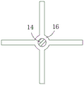
fig. 2 isbase:Sub>A sectional view taken along the linebase:Sub>A-base:Sub>A of fig. 1 according to the present invention;
fig. 3 is a partial schematic view of a second turret of fig. 1 according to the present invention.
In the figure: 1. a body; 2. a wall scraping rod; 3. crushing the tips; 4. stirring blades; 5. a discharge pipe; 6. supporting legs; 7. a first rotating frame; 8. a first motor; 9. a guide hole; 10. a first rotating shaft; 11. a connecting rod; 12. a feeding pipe; 13. a second motor; 14. a second rotating shaft; 15. spirally lifting the material leaves; 16. a second rotating frame.
Detailed Description
The technical solutions in the embodiments of the present invention will be described clearly and completely with reference to the drawings in the embodiments of the present invention, and it is obvious that the described embodiments are only some embodiments of the present invention, not all embodiments. Based on the embodiments in the present invention, all other embodiments obtained by a person skilled in the art without creative efforts all belong to the protection scope of the present invention.
Example 1
Referring to fig. 1, 2 and 3, the sand mixer for a mechanical casting production line in the figures includes a machine body 1, a first rotating frame 7 is installed at the bottom end inside the machine body 1, a second rotating frame 16 is installed at the top end inside the machine body 1, the second rotating frame 16 and the first rotating frame 7 are aligned up and down and are parallel to each other, and a first rotating shaft 10 penetrates through the middle inside the machine body 1.
First motor 8 is installed to the bottom of organism 1, and first motor 8's top is connected with the bottom of first pivot 10, and first pivot 10 rotates with organism 1 to be connected, the vertical setting of first pivot 10.
The surface of the first rotating shaft 10 is connected with a spiral lifting material blade 15 which is used for spirally lifting and dispersing a large number of gravels stacked in the middle of the machine body 1 from the bottom end, so that the stacked gravels can be turned up and down; the middle of the first rotating frame 7 is provided with a guide hole 9, the first rotating shaft 10 penetrates through the guide hole 9, and the bottom end of the first rotating shaft 10 is rotatably connected with the bottom end of the second rotating frame 16.
A connecting rod 11 is fixed between the first rotating frame 7 and the second rotating frame 16, and the connecting rod 11 is parallel to the wall scraping rod 2 and is used for reinforcing the stirring blade 4; connecting rod 11 with scrape fixedly connected with stirring vane 4 between the wall pole 2, 4 levels of stirring vane set up to interval distribution is in connecting rod 11 with scrape in the middle of the wall pole 2 for mix the gravel stirring.
The two sides of the stirring blade 4 are fixed with the crushing tips 3, and the crushing tips 3 are in a conical structure and used for crushing and loosening the bonded and agglomerated gravel.
Install second motor 13 in the middle of the top of organism 1, the bottom of second motor 13 is connected with second pivot 14, and inside second pivot 14 rotated and inserted organism 1, fixed connection in the middle of the bottom of second pivot 14 and the top of second swivel mount 16 for it is rotatory to drive first swivel mount 7 and second swivel mount 16.
The rotation direction of the stirring blade 4 and the rotation direction of the spiral lifting blade 15 can be consistent or opposite, and the rotation between the stirring blade 4 and the spiral lifting blade 15 does not interfere with each other and does not collide with each other.
The top of organism 1 is provided with filling tube 12, and the bottom mounting of organism 1 has supporting leg 6, and the side bottom of organism 1 is provided with the discharging pipe.
This mechanical casting production line roller mill, during the use: set up first swivel mount 7 and second swivel mount 16 in organism 1 inside to set up stirring leaf 4 between the two, stirring leaf 4 fixed surface smashes sharp 3, smashes sharp 3 and smashes the gravel of conglomerating to bonding.
Meanwhile, a first rotating shaft 10 penetrates through the middle inside the machine body 1, a spiral lifting blade 15 is connected to the surface of the first rotating shaft 10, and the stirring blades 4 are located on the periphery of the spiral lifting blade 15, rotate mutually, do not interfere and do not collide.
In the process of mixing gravel by the sand mixer, the second motor 13 drives the first rotating frame 7 and the second rotating frame 16 to rotate and drives the stirring blades 4 to rotate, so as to stir and mix gravel in the machine body 1; simultaneously, first motor 8 drives pivot 10 and spiral shell of rising 15 is rotatory, to 1 inside middle more gravel of piling up of organism, from bottom spiral shell's rise and dispersion for can turn from top to bottom of the gravel of piling up, cooperation stirring leaf 4 can be to the gravel intensive mixing.
Example 2
Referring to fig. 1, 2 and 3, the embodiment further illustrates an embodiment 1, in which a sand mixer for a mechanical casting production line includes a machine body 1, a first rotating frame 7 is installed at a bottom end inside the machine body 1, a second rotating frame 16 is installed at a top end inside the machine body 1, and a first rotating shaft 10 passes through a middle inside the machine body 1.
The first rotating frame 7 and the second rotating frame 16 are both of a cross structure, the wall scraping rod 2 is fixed between the first rotating frame 7 and the second rotating frame 16, and the wall scraping rod 2 is vertically arranged; the side surface of the wall scraping rod 2 is in contact with the inner surface of the machine body 1 and is used for scraping the gravel adhered to the inner surface of the machine body 1.
The machine body 1 is of a cylindrical structure, and the first rotating frame 7 and the second rotating frame 16 are in sliding contact with the inner surface of the machine body 1; a connecting rod 11 is fixed between the first rotating frame 7 and the second rotating frame 16, a stirring blade 4 is fixedly connected between the connecting rod 11 and the wall scraping rod 2, and the stirring blade 4 is horizontally arranged.
The second motor 13 is installed on the top of the machine body 1, the bottom end of the second motor 13 is connected with a second rotating shaft 14, and the bottom end of the second rotating shaft 14 is fixedly connected with the middle of the top end of a second rotating frame 16.
In this embodiment, the first rotating frame 7 and the second rotating frame 16 are provided inside the machine body 1, and the wall scraping rod 2 is provided therebetween, and the wall scraping rod 2 is in contact with the inner surface of the machine body 1.
In the sand mixing process of the sand mixer, the second motor 13 drives the second rotating frame 16 to rotate through the second rotating shaft 14, so that the first rotating frame 7 is driven to rotate, the wall scraping rod 2 scrapes and cleans the inner surface of the machine body 1, the gravel is reduced to be bonded on the inner surface of the machine body 1, and the quantity of the gravel discharged material is not reduced and the cleaning machine body 1 is convenient to clean in the later period.
It is noted that, herein, relational terms such as first and second, and the like may be used solely to distinguish one entity or action from another entity or action without necessarily requiring or implying any actual such relationship or order between such entities or actions. Also, the terms "comprises," "comprising," or any other variation thereof, are intended to cover a non-exclusive inclusion, such that a process, method, article, or apparatus that comprises a list of elements does not include only those elements but may include other elements not expressly listed or inherent to such process, method, article, or apparatus.
Although embodiments of the present invention have been shown and described, it will be appreciated by those skilled in the art that changes, modifications, substitutions and alterations can be made in these embodiments without departing from the principles and spirit of the invention, the scope of which is defined in the appended claims and their equivalents.
Claims (8)
1. The utility model provides a mechanical casting production line roller mill which characterized in that includes: organism (1), first swivel mount (7) are installed to the inside bottom of organism (1), second swivel mount (16) are installed on the inside top of organism (1), first pivot (10) have been passed in the middle of the inside of organism (1).
2. The mechanical casting production line roller mill of claim 1, characterized in that: first motor (8) are installed to the bottom of organism (1), the top of first motor (8) with the bottom of first pivot (10) is connected, first pivot (10) with organism (1) rotates and is connected.
3. The mechanical casting production line roller mill of claim 1, characterized in that: the surface of first pivot (10) is connected with spiral shell screwing in material leaf (15), open the centre of first swivel mount (7) has guiding hole (9), first pivot (10) are passed guiding hole (9), the bottom of first pivot (10) with the bottom of second swivel mount (16) is rotated and is connected.
4. The mechanical casting production line roller mill of claim 1, characterized in that: the first rotating frame (7) and the second rotating frame (16) are both of a cross structure, a wall scraping rod (2) is fixed between the first rotating frame (7) and the second rotating frame (16), the side face of the wall scraping rod (2) is in contact with the inner surface of the machine body (1), and the machine body (1) is of a cylindrical structure.
5. The mechanical casting production line roller mill of claim 4, wherein: first swivel mount (7) with be fixed with connecting rod (11) between second swivel mount (16), connecting rod (11) with scrape fixedly connected with stirring leaf (4) between wall pole (2), stirring leaf (4) level sets up.
6. The mechanical casting production line roller mill of claim 5, wherein: crushing tips (3) are fixed on two sides of the stirring blades (4), and the crushing tips (3) are of conical structures.
7. The mechanical casting production line roller mill of claim 1, characterized in that: second motor (13) are installed on the top of organism (1), the bottom of second motor (13) is connected with second pivot (14), the bottom of second pivot (14) with fixed connection in the middle of the top of second swivel mount (16).
8. The mechanical casting production line roller mill of claim 1, characterized in that: the top of organism (1) is provided with filling tube (12), the bottom mounting of organism (1) has supporting leg (6), the side bottom of organism (1) is provided with the discharging pipe.
Priority Applications (1)
| Application Number | Priority Date | Filing Date | Title |
|---|---|---|---|
| CN202222929422.XU CN218395804U (en) | 2022-11-03 | 2022-11-03 | Mechanical casting production line roller mill |
Applications Claiming Priority (1)
| Application Number | Priority Date | Filing Date | Title |
|---|---|---|---|
| CN202222929422.XU CN218395804U (en) | 2022-11-03 | 2022-11-03 | Mechanical casting production line roller mill |
Publications (1)
| Publication Number | Publication Date |
|---|---|
| CN218395804U true CN218395804U (en) | 2023-01-31 |
Family
ID=85007006
Family Applications (1)
| Application Number | Title | Priority Date | Filing Date |
|---|---|---|---|
| CN202222929422.XU Active CN218395804U (en) | 2022-11-03 | 2022-11-03 | Mechanical casting production line roller mill |
Country Status (1)
| Country | Link |
|---|---|
| CN (1) | CN218395804U (en) |
-
2022
- 2022-11-03 CN CN202222929422.XU patent/CN218395804U/en active Active
Similar Documents
| Publication | Publication Date | Title |
|---|---|---|
| CN109200869B (en) | Gravel and sand mixing apparatus | |
| CN108187828A (en) | A kind of coating material production material milling apparatus convenient for cleaning | |
| CN209423518U (en) | A kind of chemical industry measurement mixing plant | |
| CN209271552U (en) | A kind of raw material grinding device of the manufacture of cement with screening function | |
| CN218395804U (en) | Mechanical casting production line roller mill | |
| CN207736520U (en) | A kind of aggregate mixing arrangement for producing foam concrete | |
| CN213791165U (en) | Powder stirring and mixing device for building decoration | |
| CN206366416U (en) | A kind of graphite produces and processes device | |
| CN215234494U (en) | Chemical industry coating production is with mixing grinder | |
| CN214768710U (en) | Sand mixing device for casting machine for hardware production | |
| CN211389460U (en) | Filter type concrete mixer | |
| CN207549220U (en) | A kind of recycling rubber reducing mechanism | |
| CN210993840U (en) | Automobile coating agitating unit of stirring | |
| CN207823861U (en) | A kind of casting model powder horizontal revolving drum sand mixer | |
| CN218744688U (en) | Casting machinery sand mulling equipment that shaping rate is high | |
| CN210210916U (en) | Height-adjustable discharge hopper | |
| CN220387811U (en) | Anti-blocking sand mixer | |
| CN219424206U (en) | Magnesia prefab agitating unit for ladle | |
| CN216024396U (en) | Asphalt concrete production agitating unit | |
| CN220614462U (en) | Concrete sleeper raw materials agitating unit that produces | |
| CN210787208U (en) | Raw material mixing device is used in production of concrete polycarboxylate water reducing agent | |
| CN216465381U (en) | Recycled concrete compounding agitating unit | |
| CN212826073U (en) | Mixed material device for concrete production | |
| CN217595810U (en) | Precoated sand mixer for fully mixing auxiliary materials and coating | |
| CN213995701U (en) | Chemical production device |
Legal Events
| Date | Code | Title | Description |
|---|---|---|---|
| GR01 | Patent grant | ||
| GR01 | Patent grant |