CN218378607U - Installation component for electronic information screen - Google Patents
Installation component for electronic information screen Download PDFInfo
- Publication number
- CN218378607U CN218378607U CN202222812847.2U CN202222812847U CN218378607U CN 218378607 U CN218378607 U CN 218378607U CN 202222812847 U CN202222812847 U CN 202222812847U CN 218378607 U CN218378607 U CN 218378607U
- Authority
- CN
- China
- Prior art keywords
- electronic information
- information screen
- rubber plate
- plate
- clamping structure
- Prior art date
- Legal status (The legal status is an assumption and is not a legal conclusion. Google has not performed a legal analysis and makes no representation as to the accuracy of the status listed.)
- Active
Links
Images


Abstract
The utility model discloses an electronic information screen is with installation component relates to electron technical field. The mounting assembly for the electronic information screen comprises a base, a supporting frame, a first clamping structure, a second clamping structure and a lifting driving structure. The first clamping structure comprises a fixing plate and a first rubber plate fixedly installed at the bottom of the fixing plate. The second clamping structure comprises a cross-shaped clamping plate and a second rubber plate fixedly arranged at the top of the cross-shaped clamping plate; the first rubber plate and the second rubber plate are respectively movably connected with the top and the bottom of the electronic information screen in a contact mode. The utility model relates to an installation component for electronic information screen can satisfy the quick assembly disassembly of its information display position through nimble centre gripping electronic information screen, and the clamping action has satisfied the assembly protection that the electronic information screen flexibility touched the pressure, so solved the inconvenient nature that the electronic information screen adopted traditional screw to carry out the fastening.
Description
Technical Field
The utility model belongs to the technical field of electronic information, especially, relate to an electronic information is installation component for screen.
Background
Electronic information is generally displayed by adopting a display screen and a publicizing means for publically and widely transmitting information to the public through a certain form of media. Compared with the traditional paper propaganda material, the paper propaganda material has the advantages of saving paper resources, no need of repeated printing, capability of timely modifying exhibition information and the like, so that the paper propaganda material is widely popularized and applied to the fields of exhibition, promotion, advertising and the like.
At present, when the electronic information screen is assembled in an actual application field, a plurality of screws are usually adopted to be fastened and connected with a support to stabilize a display position, although the screws are adopted, the stability of the display position of the electronic information screen can be enhanced, when the electronic information screen is frequently applied to various occasions, the electronic information screen needs to be frequently assembled and disassembled through the assembling and disassembling screws, the assembling process is high in complexity, and the bolts are easily broken due to the fact that the bolts are matched with the screw thread holes for a long time in a twisting mode, so that the assembling and the using of the electronic information screen are affected.
Therefore the utility model provides an installation component for electronic information screen.
SUMMERY OF THE UTILITY MODEL
An object of the utility model is to provide an installation component for electronic information screen through setting up first clamping structure, second clamping structure and lift drive structure, can solve the inconvenient problem of electronic information screen dismouting.
In order to solve the technical problem, the utility model discloses a realize through following technical scheme:
a mounting assembly for an electronic information screen includes a base;
the mounting assembly further comprises:
a support frame;
the first clamping structure is fixedly arranged on the inner side of the support frame; the first clamping structure comprises a fixed plate and a first rubber plate fixedly arranged at the bottom of the fixed plate;
the second clamping structure is movably arranged on the inner side of the supporting frame and is arranged right below the first rubber plate; the second clamping structure comprises a cross-shaped clamping plate and a second rubber plate fixedly arranged at the top of the cross-shaped clamping plate; the first rubber plate and the second rubber plate are respectively movably connected with the top and the bottom of the electronic information screen in a contact manner; and
a lifting drive structure for providing lifting power based on the second clamping structure in the support frame.
Above-mentioned installation component for electronic information screen can satisfy the quick assembly disassembly of its information display position through nimble centre gripping electronic information screen, and the clamping action has satisfied the assembly protection that the electronic information screen flexibility touched and pressed, so solved the inconvenience that electronic information screen adoption traditional screw fastens.
Furthermore, the opposite surfaces of the first rubber plate and the second rubber plate are provided with clamping grooves, and the electronic information screen is movably abutted in the clamping grooves corresponding to the first rubber plate and the second rubber plate.
Furthermore, the inner side wall of the support frame is provided with a guide sliding groove matched with the cross-shaped clamping plate, and the cross-shaped clamping plate is connected to the inner side of the support frame through the guide sliding groove in a sliding mode.
Furthermore, the lifting driving structure comprises a bidirectional threaded rod which is rotatably connected to the inner side of the support frame, a hand wheel which is coaxially fixed at one end of the bidirectional threaded rod, two transmission threaded sleeves which are in threaded connection on the bidirectional threaded rod and a hinge rod which is movably hinged to the top of each transmission threaded sleeve.
Furthermore, the hand wheel is arranged on one side back to the support frame.
Furthermore, the top ends of the two hinge rods are movably hinged to the bottom of the cross-shaped clamping plate.
The utility model discloses following beneficial effect has:
the utility model discloses a set up first clamping structure and second clamping structure, provide second clamping structure with lift power by lift drive structure, second clamping structure can be towards or the motion of first clamping structure dorsad to satisfy and be applied to the electronic information screen between second clamping structure and the first clamping structure and realize nimble clamping as the purpose, improve the assembly efficiency of electronic information screen.
Drawings
In order to more clearly illustrate the technical solutions of the embodiments of the present invention, the drawings used in the description of the embodiments are briefly introduced below, it is obvious that the drawings in the description below are only some embodiments of the present invention, and for those skilled in the art, other drawings can be obtained according to the drawings without creative efforts.
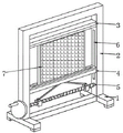
Fig. 1 is a schematic structural view of a mounting assembly for an electronic information screen according to the present invention;
FIG. 2 is a schematic view of the electronic information screen of FIG. 1 according to the present invention;
fig. 3 is a schematic view of a second clamping structure of fig. 2 according to the present invention.
In the drawings, the reference numbers indicate the following list of parts:
1. a base; 2. a support frame; 3. a first clamping structure; 31. a fixing plate; 32. a first rubber sheet; 4. a second clamping structure; 41. a cross-shaped splint; 42. a second rubber sheet; 5. a lifting drive structure; 51. a bidirectional threaded rod; 52. a hand wheel; 53. a transmission threaded sleeve; 54. a hinged lever; 6. a guide chute; 7. an electronic information screen.
Detailed Description
The technical solution in the embodiments of the present invention will be clearly and completely described below with reference to the accompanying drawings in the embodiments of the present invention.
Example one
Referring to fig. 1-3, the present invention is a first embodiment of an electronic information screen mounting assembly, in which the electronic information screen mounting assembly includes a base 1; the base 1 in this embodiment is of an i-shaped structure, which can provide stability for the floor support.
The mounting component for the electronic information screen further comprises a support frame 2, a first clamping structure 3 and a second clamping structure 4.
Wherein, the first clamping structure 3 is fixedly arranged at the inner side of the support frame 2; the first clamping structure 3 comprises a fixed plate 31 and a first rubber plate 32 fixedly arranged at the bottom of the fixed plate 31;
wherein, the second clamping structure 4 is movably arranged at the inner side of the supporting frame 2 and is arranged at the position right below the first rubber plate 32; the second clamping structure 4 comprises a cross-shaped clamping plate 41 and a second rubber plate 42 fixedly arranged at the top of the cross-shaped clamping plate 41; the first rubber sheet 32 and the second rubber sheet 42 are movably in contact with the top and bottom positions of the electronic information screen 7, respectively. The electronic information screen 7 in this embodiment can be used as a display panel for electronic information, and can be externally connected to a terminal, i.e., a host, to achieve uploading and imaging of electronic information data.
The opposite surfaces of the first rubber plate 32 and the second rubber plate 42 are both provided with a clamping groove, and the electronic information screen 7 is movably abutted in the corresponding clamping grooves of the first rubber plate 32 and the second rubber plate 42; the card slot can enable the electronic information screen 7 to be flexibly abutted against the corresponding first rubber plate 32 and the second rubber plate 42, so that the protection of flexible touch pressure of the electronic information screen 7 is met.
The inner side wall of the support frame 2 is provided with a guide chute 6 matched with the cross-shaped clamping plate 41, and the cross-shaped clamping plate 41 is connected to the inner side of the support frame 2 in a sliding manner through the guide chute 6; the guide runner 6 enables the cross clamp plate 41 to slide stably in the vertical direction inside the support frame 2.
Example two
Referring to fig. 1-3, the second embodiment of the mounting assembly for an electronic information screen according to the present invention is improved from the first embodiment in that the mounting assembly for an electronic information screen further comprises a lifting driving structure 5.
Wherein, the lifting driving structure 5 provides lifting power for the second clamping structure 4 in the supporting frame 2; the lifting driving structure 5 comprises a bidirectional threaded rod 51, a hand wheel 52, two transmission threaded sleeves 53 and a hinge rod 54, wherein the bidirectional threaded rod 51 is rotatably connected to the inner side of the support frame 2 through a bearing, the hand wheel 52 is coaxially fixed at one end of the bidirectional threaded rod 51, the two transmission threaded sleeves 53 are in threaded connection with the bidirectional threaded rod 51, and the hinge rod 54 is movably hinged to the top of each transmission threaded sleeve 53; the hand wheel 52 is arranged at one side back to the support frame 2; the hand wheel 52 is used for driving the bidirectional threaded rod 51 to rotate axially; in the present embodiment, the two pairs of threads of the bidirectional threaded rod 51 are oppositely disposed.
The top ends of the two hinge rods 54 are movably hinged at the bottom of the cross-shaped clamping plate 41; two ends of the hinge rod 54 are movably hinged with the transmission threaded sleeve 53 and the cross-shaped clamping plate 41 through hinge seats.
Specifically, when the electronic information screen 7 needs to be installed at a display position, the base 1 and the support frame 2 are arranged in a field, then when it is ensured that a reserved gap between the first rubber plate 32 and the second rubber plate 42 is larger than that of the electronic information screen 7, the bottom frame of the electronic information screen 7 can be placed in the clamping groove of the second rubber plate 42, the two transmission threaded sleeves 53 are made to approach each other on the bidirectional threaded rod 51 by rotating the hand wheel 52, the two adjacent transmission threaded sleeves 53 can lift the cross-shaped clamping plate 41 through the corresponding hinged rods 54, the cross-shaped clamping plate 41 is made to approach towards the first rubber plate 32 until the top frame of the electronic information screen 7 is in contact with and pressed in the clamping groove of the first rubber plate 32, and clamping and fixing of the display position of the electronic information screen 7 can be achieved; similarly, the hand wheel 52 is rotated to make the two transmission thread sleeves 53 away from each other on the bidirectional threaded rod 51, and the cross-shaped clamping plate 41 can move downwards away from the first rubber plate 32, so that the electronic information screen 7 can be assembled and disassembled.
The above is only the preferred embodiment of the present invention, and the present invention is not limited thereto, any technical solutions recorded in the foregoing embodiments are modified, and some technical features thereof are replaced with equivalent ones, and any modification, equivalent replacement, and improvement made thereby all belong to the protection scope of the present invention.
Claims (7)
1. A mounting assembly for an electronic information screen, comprising a base (1);
it is characterized by also comprising:
a support frame (2);
the first clamping structure (3) is fixedly arranged on the inner side of the support frame (2); the first clamping structure (3) comprises a fixing plate (31) and a first rubber plate (32) fixedly mounted at the bottom of the fixing plate (31);
the second clamping structure (4) is movably arranged on the inner side of the support frame (2) and is arranged right below the first rubber plate (32); the second clamping structure (4) comprises a cross-shaped clamping plate (41) and a second rubber plate (42) fixedly mounted at the top of the cross-shaped clamping plate (41); the first rubber plate (32) and the second rubber plate (42) are respectively movably contacted with the top and bottom positions of the electronic information screen (7).
2. A mounting assembly for an electronic information screen according to claim 1, further comprising a lifting drive structure (5) for providing lifting power to the second clamping structure (4) based within the support frame (2).
3. The mounting assembly for the electronic information screen, according to claim 2, wherein the opposite surfaces of the first rubber plate (32) and the second rubber plate (42) are provided with a slot, and the electronic information screen (7) is movably abutted against the corresponding slots of the first rubber plate (32) and the second rubber plate (42).
4. The mounting assembly for the electronic information screen according to claim 2, wherein a guide sliding groove (6) matched with the cross-shaped clamping plate (41) is formed in the inner side wall of the supporting frame (2), and the cross-shaped clamping plate (41) is slidably connected to the inner side of the supporting frame (2) through the guide sliding groove (6).
5. The mounting assembly for the electronic information screen according to claim 2, wherein the lifting driving structure (5) comprises a bidirectional threaded rod (51) rotatably connected to the inner side of the support frame (2), a hand wheel (52) coaxially fixed at one end of the bidirectional threaded rod (51), two transmission threaded sleeves (53) screwed on the bidirectional threaded rod (51), and a hinge rod (54) movably hinged at the top of each transmission threaded sleeve (53).
6. A mounting assembly for an electronic information screen according to claim 5, characterised in that the hand wheel (52) is arranged on the side facing away from the support frame (2).
7. A mounting assembly for an electronic information screen according to claim 6, characterized in that the top ends of the two hinge levers (54) are each movably hinged at the bottom of the cross-shaped clamping plate (41).
Priority Applications (1)
| Application Number | Priority Date | Filing Date | Title |
|---|---|---|---|
| CN202222812847.2U CN218378607U (en) | 2022-10-25 | 2022-10-25 | Installation component for electronic information screen |
Applications Claiming Priority (1)
| Application Number | Priority Date | Filing Date | Title |
|---|---|---|---|
| CN202222812847.2U CN218378607U (en) | 2022-10-25 | 2022-10-25 | Installation component for electronic information screen |
Publications (1)
| Publication Number | Publication Date |
|---|---|
| CN218378607U true CN218378607U (en) | 2023-01-24 |
Family
ID=84934171
Family Applications (1)
| Application Number | Title | Priority Date | Filing Date |
|---|---|---|---|
| CN202222812847.2U Active CN218378607U (en) | 2022-10-25 | 2022-10-25 | Installation component for electronic information screen |
Country Status (1)
| Country | Link |
|---|---|
| CN (1) | CN218378607U (en) |
-
2022
- 2022-10-25 CN CN202222812847.2U patent/CN218378607U/en active Active
Similar Documents
| Publication | Publication Date | Title |
|---|---|---|
| CN111312086B (en) | Quick splicing structure of LED display screen module | |
| CN218378607U (en) | Installation component for electronic information screen | |
| WO2016110176A1 (en) | Replaceable guiding sign and assembly method therefor | |
| CN210325110U (en) | Information bulletin board for construction management | |
| CN218630675U (en) | Mechanism assembly for disassembling computer panel | |
| CN211399070U (en) | Embedded support | |
| CN212750270U (en) | Commercial display screen of LED wisdom | |
| CN110675758B (en) | Large-scale assembled outdoor display screen | |
| CN219979070U (en) | LED energy-saving display screen | |
| CN207947043U (en) | A kind of outdoor billboard for multimedia advertising displaying | |
| CN216719399U (en) | LED display screen convenient to dismantle | |
| CN216868011U (en) | LED display screen convenient to dismantle | |
| CN218728883U (en) | Computer mainboard fixed knot constructs | |
| CN206342127U (en) | A kind of office desk screen | |
| CN111585073A (en) | Computer display card interface connecting device | |
| CN205809800U (en) | One is applied to the tool-free fixing device of Servers standard card | |
| CN216143413U (en) | Combined LED display screen convenient to install | |
| CN213299398U (en) | LED display screen for information distribution | |
| CN220305742U (en) | A quick-witted case structure for fixing industrial computer | |
| CN215073109U (en) | Rigid-flex printed circuit board | |
| CN218268279U (en) | Double-screen desk type cash register convenient for adjusting screen angle | |
| CN212541234U (en) | Conveniently dismantle mounting structure who overhauls mainboard | |
| CN220540659U (en) | Billboard mounting structure | |
| CN220171491U (en) | Computer case with independent display structure | |
| CN218675894U (en) | Touch all-in-one that waterproof dirt resistance is good |
Legal Events
| Date | Code | Title | Description |
|---|---|---|---|
| GR01 | Patent grant | ||
| GR01 | Patent grant | ||
| CP02 | Change in the address of a patent holder |
Address after: No. 8 Tianxin Street, Taihe Town, Baiyun District, Guangzhou City, Guangdong Province, 510540 Patentee after: Chen Liufu Address before: 425805 Group 4, Wangtian Village, Tushi Township, Lanshan County, Yongzhou City, Hunan Province Patentee before: Chen Liufu |
|
| CP02 | Change in the address of a patent holder |