CN218349409U - Novel laser displacement sensor - Google Patents
Novel laser displacement sensor Download PDFInfo
- Publication number
- CN218349409U CN218349409U CN202222169058.1U CN202222169058U CN218349409U CN 218349409 U CN218349409 U CN 218349409U CN 202222169058 U CN202222169058 U CN 202222169058U CN 218349409 U CN218349409 U CN 218349409U
- Authority
- CN
- China
- Prior art keywords
- displacement sensor
- laser displacement
- seat
- connecting seat
- limiting
- Prior art date
- Legal status (The legal status is an assumption and is not a legal conclusion. Google has not performed a legal analysis and makes no representation as to the accuracy of the status listed.)
- Active
Links
Images


Landscapes
- Length Measuring Devices By Optical Means (AREA)
Abstract
The utility model discloses a novel laser displacement sensor, including laser displacement sensor, connecting seat and mount pad, laser displacement sensor's surface is provided with rotates the seat, and the connecting seat is connected with laser displacement sensor, and the mount pad rotates with the connecting seat to be connected. The utility model has the advantages that: under the effect of spacing subassembly, make to rotate the seat and rotate along the connecting seat, it is in suitable angle to drive laser displacement sensor to rotate, and to laser displacement sensor's rigidity under the effect of spacing subassembly, under the effect of supporting component, when making the connecting seat remove suitable position, thereby laser displacement sensor also removes and is in suitable position, be convenient for under the different situation, to the measurement of object different positions, make the suitability stronger, need not additionally increase laser displacement sensor.
Description
Technical Field
The utility model relates to a laser displacement sensor specifically is a novel laser displacement sensor, belongs to displacement sensor technical field.
Background
The laser displacement sensor is a sensor for measuring by using a laser technology, and consists of a laser, a laser detector and a measuring circuit.
The laser irradiates an object, and the rebounded light is detected under the action of the laser detector, so that the detection is finished.
The existing laser displacement sensors are fixedly installed, the positions of the laser displacement sensors cannot be adjusted according to actual use conditions, when data of different surfaces of an object are detected according to requirements, different laser displacement sensors need to be added to detect, the detection is quite wasteful, and therefore a novel laser displacement sensor is provided.
SUMMERY OF THE UTILITY MODEL
An object of the utility model is to provide a novel laser displacement sensor just in order to solve above-mentioned problem.
The utility model discloses a following technical scheme realizes above-mentioned purpose, a novel laser displacement sensor, include:
the outer surface of the laser displacement sensor is provided with a rotating seat;
the connecting seat is connected with the laser displacement sensor;
the mounting seat is rotatably connected with the connecting seat;
the method is characterized in that: a limiting assembly is arranged between the laser displacement sensor and the connecting seat, the limiting assembly comprises two fixing seats, a limiting sleeve and a limiting gear, and the two fixing seats are arranged on the upper surface of the connecting seat;
the connecting seat and the mounting seat are provided with supporting components, each supporting component comprises a screw rod, a moving seat and a supporting rod, and the screw rods are rotatably connected to the inner wall of the mounting seat.
Preferably, the outer surface of the laser displacement sensor is provided with a connecting line, and the lower surface of the laser displacement sensor is provided with a light source.
Preferably, the rotating seat is rotatably connected between the two fixed seats, the laser displacement sensor is rotatably connected with the connecting seat through the rotating seat, and one end of the rotating seat is connected with a limiting gear.
Preferably, the limiting gear is arranged inside one of the fixing seats, the outer surface of the limiting gear is meshed with the limiting sleeve, and the limiting sleeve is connected to the inner wall of the fixing seat in a sliding mode.
Preferably, limit sleeve's one end is connected with connecting rod and spring, the other end of spring is connected with the inner wall of fixing base, connecting rod sliding connection is on the inner wall of fixing base.
Preferably, the movable base is in threaded connection with the outer surface of the screw rod, the supporting rod is in rotary connection with the inner wall of the movable base, and the other end of the supporting rod is in rotary connection with the inner wall of the connecting base.
The beneficial effects of the utility model are that: under the effect of spacing subassembly, make the rotation seat rotate along the connecting seat, it is in suitable angle to drive laser displacement sensor rotation, and fix the rotation seat under the effect of spacing subassembly, thereby make laser displacement sensor's position fixed, under supporting component's effect, when making the connecting seat remove suitable position, thereby laser displacement sensor also removes and is in suitable position, be convenient for under the different situation, to the measurement of object different positions, make the suitability stronger, need not additionally increase laser displacement sensor.
Drawings
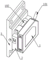
FIG. 1 is a schematic structural view of the present invention;
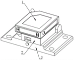
FIG. 2 is a schematic side view of the present invention;
FIG. 3 is a sectional view of the fixing base of the present invention;
fig. 4 is a sectional view of the mounting base of the present invention;
FIG. 5 is an enlarged view of A in FIG. 3 according to the present invention;
fig. 6 is an enlarged view of B in fig. 4 according to the present invention.
In the figure: 1. a laser displacement sensor; 101. a connecting wire; 102. a rotating seat; 2. a connecting seat; 3. a mounting seat; 4. a fixed seat; 401. a connecting rod; 402. a limiting sleeve; 403. a spring; 404. a limit gear; 5. a screw rod; 501. a movable seat; 502. a support rod.
Detailed Description
The technical solutions in the embodiments of the present invention will be described clearly and completely with reference to the accompanying drawings in the embodiments of the present invention, and it is obvious that the described embodiments are only some embodiments of the present invention, not all embodiments. Based on the embodiments in the present invention, all other embodiments obtained by a person skilled in the art without creative work belong to the protection scope of the present invention.
The embodiment of the utility model discloses novel laser displacement sensor.
According to the attached drawings 1 and 2, the laser displacement sensor comprises a laser displacement sensor 1, a connecting seat 2 and a mounting seat 3, wherein a rotating seat 102 is arranged on the outer surface of the laser displacement sensor 1, the connecting seat 2 is connected with the laser displacement sensor 1, the mounting seat 3 is rotatably connected with the connecting seat 2, a connecting wire 101 is arranged on the outer surface of the laser displacement sensor 1, and a light source is arranged on the lower surface of the laser displacement sensor 1;
when the laser displacement sensor 1 is required to be used for measuring data of an object, firstly, a light source on the laser displacement sensor 1 is required to be opposite to a measuring surface of the object, and at the moment, the laser displacement sensor 1 is adjusted according to the measuring surface of the object to be measured;
firstly, under the action of a limiting assembly, the rotating seat 102 rotates along the connecting seat 2 to drive the laser displacement sensor 1 to rotate at a proper angle, and the rotating seat 102 is fixed under the action of the limiting assembly, so that the position of the laser displacement sensor 1 is fixed;
under supporting component's effect for when connecting seat 2 removed suitable position, thereby laser displacement sensor 1 also removes and is in suitable position, under the different situation of being convenient for, to the measurement of object different positions, makes the suitability stronger, need not additionally increase laser displacement sensor 1.
According to fig. 3 and 5, a limiting assembly is arranged between the laser displacement sensor 1 and the connecting seat 2, the limiting assembly comprises two fixing seats 4, a limiting sleeve 402 and a limiting gear 404, and the two fixing seats 4 are arranged on the upper surface of the connecting seat 2;
the rotating seat 102 is rotatably connected between the two fixed seats 4, the laser displacement sensor 1 is rotatably connected with the connecting seat 2 through the rotating seat 102, one end of the rotating seat 102 is connected with a limiting gear 404, the limiting gear 404 is positioned inside one of the fixed seats 4, and the outer surface of the limiting gear 404 is meshed with the limiting sleeve 402;
the limiting sleeve 402 is connected to the inner wall of the fixed seat 4 in a sliding manner, one end of the limiting sleeve 402 is connected with the connecting rod 401 and the spring 403, the other end of the spring 403 is connected with the inner wall of the fixed seat 4, and the connecting rod 401 is connected to the inner wall of the fixed seat 4 in a sliding manner;
firstly, the connecting rod 401 is pulled, so that the limiting sleeve 402 slides on the inner walls of the fixed seats 4, at the same time, the spring 403 is compressed under the movement of the limiting sleeve 402, at the same time, the limiting sleeve 402 is separated from the limiting gear 404, and at the same time, the laser displacement sensor 1 can be rotated to drive the rotating seat 102 to rotate on the inner walls of the two fixed seats 4;
make laser displacement sensor 1 be in suitable angle, loosen connecting rod 401 this moment, under the bounce-back of spring 403 for spacing sleeve 402 is reverse slip on the inner wall of fixing base 4, makes spacing sleeve 402 and limiting gear 404 mesh mutually, thereby fixes limiting gear 404, and then fixes rotating seat 102, makes laser displacement sensor 1's position fixed.
According to fig. 4 and fig. 6, the connecting seat 2 and the mounting seat 3 are provided with a supporting assembly, the supporting assembly comprises a screw rod 5, a moving seat 501 and a supporting rod 502, and the screw rod 5 is rotatably connected to the inner wall of the mounting seat 3;
the movable base 501 is in threaded connection with the outer surface of the screw rod 5, the support rod 502 is rotatably connected to the inner wall of the movable base 501, and the other end of the support rod 502 is rotatably connected to the inner wall of the connecting base 2;
at this time, the screw rod 5 is rotated, so that the moving seat 501 moves, and the supporting rod 502 is driven to move and rotate, so that the supporting rod 502 pushes the connecting seat 2 to rotate, and the connecting seat 2 rotates along the outer surface of the mounting seat 3;
make connecting seat 2 remove suitable position to make laser displacement sensor 1 also remove and be in suitable position, under the different situation of being convenient for, to the measurement of object different positions, make the suitability stronger, need not additionally increase laser displacement sensor 1.
The working principle is as follows: when the laser displacement sensor 1 is required to be used for measuring data of an object, firstly, a light source on the laser displacement sensor 1 is required to be opposite to a measuring surface of the object, and then the laser displacement sensor 1 is adjusted according to the measuring surface of the object required to be measured;
firstly, the connecting rod 401 is pulled to enable the limiting sleeve 402 fixedly connected with the connecting rod 401 to slide on the inner wall of the fixed seat 4, at the moment, the spring 403 fixedly connected with the limiting sleeve 402 is compressed under the movement of the limiting sleeve 402, and meanwhile, the limiting sleeve 402 is separated from the limiting gear 404 under the movement of the limiting sleeve 402;
because the limiting gear 404 is fixedly sleeved on the outer surface of the rotating seat 102, and the rotating seat 102 is rotatably connected on the outer surfaces of the two fixed seats 4, at this time, the rotating seat 102 fixedly connected with the laser displacement sensor 1 can be driven to rotate on the inner walls of the two fixed seats 4 by rotating the laser displacement sensor 1, so that the laser displacement sensor 1 is in a proper angle;
at this time, the connecting rod 401 is loosened, and under the rebounding of the spring 403, the limiting sleeve 402 reversely slides on the inner wall of the fixed seat 4, so that the limiting sleeve 402 is meshed with the limiting gear 404, the limiting gear 404 is fixed, the rotating seat 102 is further fixed, and the position of the laser displacement sensor 1 is fixed;
at this time, the screw rod 5 is rotated, and the movable seat 501 in threaded connection with the outer surface of the screw rod 5 is moved under the rotation of the screw rod 5, so that the movable seat 501 slides on the inner wall of the mounting seat 3, and the support rod 502 is rotationally connected to the movable seat 501 and the inner wall of the connecting seat 2;
meanwhile, the connecting seat 2 is rotatably connected to the outer surface of the mounting seat 3, and at the moment, the moving seat 501 moves to drive the supporting rod 502 to move and rotate, so that the supporting rod 502 pushes the connecting seat 2 to rotate, and the connecting seat 2 rotates along the outer surface of the mounting seat 3;
because connecting seat 2 and laser displacement sensor 1 rigidity this moment to when connecting seat 2 removed suitable position, make laser displacement sensor 1 also remove and be in suitable position, under the different situation of being convenient for, to the measurement of object different positions, make the suitability stronger, need not additionally increase laser displacement sensor 1.
Furthermore, it should be understood that although the present description refers to embodiments, not every embodiment may contain only a single embodiment, and such description is for clarity only, and those skilled in the art should integrate the description, and the embodiments may be combined as appropriate to form other embodiments understood by those skilled in the art.
Claims (6)
1. A novel laser displacement sensor, comprising:
the device comprises a laser displacement sensor (1), wherein a rotating seat (102) is arranged on the outer surface of the laser displacement sensor (1);
the connecting seat (2), the said connecting seat (2) links with laser displacement sensor (1);
the mounting seat (3), the mounting seat (3) is rotatably connected with the connecting seat (2);
the method is characterized in that: a limiting assembly is arranged between the laser displacement sensor (1) and the connecting seat (2), the limiting assembly comprises two fixing seats (4), a limiting sleeve (402) and a limiting gear (404), and the two fixing seats (4) are arranged on the upper surface of the connecting seat (2);
the connecting seat (2) and the mounting seat (3) are provided with a supporting assembly, the supporting assembly comprises a screw rod (5), a moving seat (501) and a supporting rod (502), and the screw rod (5) is rotatably connected to the inner wall of the mounting seat (3).
2. The novel laser displacement sensor according to claim 1, characterized in that: the outer surface of the laser displacement sensor (1) is provided with a connecting line (101), and the lower surface of the laser displacement sensor (1) is provided with a light source.
3. The novel laser displacement sensor according to claim 1, characterized in that: the laser displacement sensor is characterized in that the rotating seat (102) is rotatably connected between the two fixing seats (4), the laser displacement sensor (1) is rotatably connected with the connecting seat (2) through the rotating seat (102), and one end of the rotating seat (102) is connected with a limiting gear (404).
4. The novel laser displacement sensor according to claim 3, characterized in that: the limiting gear (404) is arranged in one of the fixing seats (4), the outer surface of the limiting gear (404) is meshed with the limiting sleeve (402), and the limiting sleeve (402) is connected to the inner wall of the fixing seat (4) in a sliding mode.
5. The novel laser displacement sensor according to claim 1, characterized in that: one end of the limiting sleeve (402) is connected with a connecting rod (401) and a spring (403), the other end of the spring (403) is connected with the inner wall of the fixing seat (4), and the connecting rod (401) is connected to the inner wall of the fixing seat (4) in a sliding mode.
6. The novel laser displacement sensor according to claim 1, characterized in that: remove seat (501) threaded connection at the surface of lead screw (5), bracing piece (502) rotate to be connected on the inner wall of removing seat (501), the other end of bracing piece (502) rotates to be connected on the inner wall of connecting seat (2).
Priority Applications (1)
| Application Number | Priority Date | Filing Date | Title |
|---|---|---|---|
| CN202222169058.1U CN218349409U (en) | 2022-08-17 | 2022-08-17 | Novel laser displacement sensor |
Applications Claiming Priority (1)
| Application Number | Priority Date | Filing Date | Title |
|---|---|---|---|
| CN202222169058.1U CN218349409U (en) | 2022-08-17 | 2022-08-17 | Novel laser displacement sensor |
Publications (1)
| Publication Number | Publication Date |
|---|---|
| CN218349409U true CN218349409U (en) | 2023-01-20 |
Family
ID=84917141
Family Applications (1)
| Application Number | Title | Priority Date | Filing Date |
|---|---|---|---|
| CN202222169058.1U Active CN218349409U (en) | 2022-08-17 | 2022-08-17 | Novel laser displacement sensor |
Country Status (1)
| Country | Link |
|---|---|
| CN (1) | CN218349409U (en) |
-
2022
- 2022-08-17 CN CN202222169058.1U patent/CN218349409U/en active Active
Similar Documents
| Publication | Publication Date | Title |
|---|---|---|
| CN204964408U (en) | Mar detects machine | |
| CN213180043U (en) | Ceiling keel perpendicularity detection device | |
| CN114102550B (en) | Laser three-dimensional remote control dust removal mapping device of crawler robot | |
| CN218349409U (en) | Novel laser displacement sensor | |
| CN219284290U (en) | Photoelectric measuring instrument with lens self-cleaning function | |
| CN210570397U (en) | Diameter measuring device is used in processing of accurate type gear | |
| CN210346698U (en) | Special measuring platform of multi-use architecture design | |
| CN218329701U (en) | Automobile wheel hub bearing measuring device | |
| CN218297111U (en) | Roughness meter for testing metal products | |
| CN114250757A (en) | Quality detection device and method for building engineering construction | |
| CN115290434A (en) | Wind-force blade detection device | |
| CN209840920U (en) | Diameter detection device is contained to pipe for building engineering | |
| CN207407839U (en) | A kind of three-coordinates measuring machine convenient for detection | |
| CN214010247U (en) | Stage mechanical motion position detection device | |
| CN219869499U (en) | Bearing machining precision detection device | |
| CN219503329U (en) | High-precision measuring instrument convenient to clean | |
| CN118209064B (en) | House building wall surface construction flatness measuring device and using method | |
| CN221223728U (en) | Automobile instrument panel bracket checking fixture | |
| CN219532072U (en) | Site measurement device used in construction | |
| CN221018973U (en) | High-precision hob group for gear hobbing machine | |
| CN216594814U (en) | Detection device for tool clamp | |
| CN218719990U (en) | Engine speed sensor support structure | |
| CN215573109U (en) | Building engineering environment monitoring device | |
| CN218212321U (en) | Detection device for processing glass cover plate | |
| CN218211275U (en) | Improved roughness measuring instrument |
Legal Events
| Date | Code | Title | Description |
|---|---|---|---|
| GR01 | Patent grant | ||
| GR01 | Patent grant |