CN218316632U - Assembled equipment room type car washer - Google Patents
Assembled equipment room type car washer Download PDFInfo
- Publication number
- CN218316632U CN218316632U CN202222879526.4U CN202222879526U CN218316632U CN 218316632 U CN218316632 U CN 218316632U CN 202222879526 U CN202222879526 U CN 202222879526U CN 218316632 U CN218316632 U CN 218316632U
- Authority
- CN
- China
- Prior art keywords
- liquid
- tank
- water
- car wash
- water tank
- Prior art date
- Legal status (The legal status is an assumption and is not a legal conclusion. Google has not performed a legal analysis and makes no representation as to the accuracy of the status listed.)
- Expired - Fee Related
Links
Images

Landscapes
- Vehicle Cleaning, Maintenance, Repair, Refitting, And Outriggers (AREA)
Abstract
本实用新型公一种组装设备间式洗车机,包括箱体,箱体内设置有清水箱、稀释洗车液水箱、洗车液原液罐、空气压缩机以及用于输出高压清水的柱塞泵组,稀释洗车液水箱的出液端第一增压泵,第一增压泵的出口经过分水器与多个车位支管连接,每个车位支管上连接一个常闭电磁阀,该电磁阀下游通过一个三通接头接来自空气压缩机的高压气源以及一个工位的泡沫支管,实现将气液混合的泡沫液经连接的泡沫支管送出;稀释洗车液水箱的进液端通过进液管路连接至洗车液原液罐。本实用新型使用组装式设备间收纳洗车机全部部件,使多个工位的洗车机统一安装在一个组装式设备间中,降低了原单工位自助洗车机外壳的生产制造成本。

The utility model discloses a car washing machine between assembly equipment, which includes a box body, which is provided with a clean water tank, a diluted car wash liquid water tank, a car wash liquid raw liquid tank, an air compressor, and a plunger pump group for outputting high-pressure clean water. The first booster pump at the liquid outlet of the car wash liquid tank, the outlet of the first booster pump is connected to multiple parking branch pipes through the water distributor, and each parking branch pipe is connected to a normally closed solenoid valve, and the downstream of the solenoid valve passes through a three-way valve. Connect the high-pressure air source from the air compressor and the foam branch pipe of a station to realize the foam liquid mixed with gas and liquid to be sent out through the connected foam branch pipe; the liquid inlet end of the diluted car wash liquid tank is connected to the car wash through the liquid inlet pipeline Liquid stock solution tank. The utility model uses the assembled equipment room to store all the parts of the car washing machine, so that the car washing machines with multiple stations are uniformly installed in one assembled equipment room, which reduces the manufacturing cost of the shell of the original single-station self-service car washing machine.
Description
技术领域technical field
本实用新型涉及自助洗车设备技术领域,特别是涉及一种组装设备间式洗车机。The utility model relates to the technical field of self-service car washing equipment, in particular to a car washing machine between assembly equipment.
背景技术Background technique
汽车的清洗要么就是在家里利用简易的清洗工具进行清洗,要么就送入到专门的洗车门面中进行清洗。然上述两种方式均存在各自的缺点。自己在家里用简易的清洗工具清洗,清洗不够彻底,清洗不干净,且无法对汽车内部空间进行清洗;在洗车门面中清洗费用较高,且受到洗车门面的地址限制,在偏远地区洗车门面少,因此无法清。因此,人们发明了自助洗车机,方便车主使用清洗汽车,如201510428468.5公开自助洗车机,包括机柜,机柜包括柜体和柜门,投币装置、刷卡装置和控制系统安装于柜门上,清水桶固定于柜体内,主水泵设置于清水供出管道上,清水供出管道的一端与清水桶的出水口连通,清水供出管道与机柜外部的清洗枪连接;泡沫剂桶固定于机柜内,泡沫剂桶的注水口与清水添加管道连通,泡沫桶的出口与泡沫供出管道的一端连通,泡沫供出管道另一端与清水供出管道连通。然而现有技术的自助洗车机为单工位洗车机,对于大型停车场等需要多个工位洗车机时,则需要安装多台自助洗车机。当自助洗车场地需要多台洗车机时,需要购买、安装多台洗车机,会使洗车机生产、安装、维护成本较高。The cleaning of the car is either done at home with simple cleaning tools, or sent to a special car wash facade for cleaning. However, the above two methods have their own shortcomings. I use simple cleaning tools to clean at home, the cleaning is not thorough enough, the cleaning is not clean, and the interior space of the car cannot be cleaned; the cleaning cost is high in the car wash facade, and the address of the car wash facade is limited, and there are few car wash facades in remote areas , so it cannot be cleared. Therefore, people have invented a self-service car washing machine, which is convenient for car owners to use to clean the car. As 201510428468.5 discloses a self-service car washing machine, including a cabinet, the cabinet includes a cabinet body and a cabinet door, a coin device, a card swiping device and a control system are installed on the cabinet door. Fixed in the cabinet, the main water pump is set on the clean water supply pipeline, one end of the clean water supply pipeline is connected to the water outlet of the clean water bucket, and the clean water supply pipeline is connected to the cleaning gun outside the cabinet; the foam agent bucket is fixed in the cabinet, and the foam agent bucket The water injection port is communicated with the clear water adding pipeline, the outlet of the foam tank is communicated with one end of the foam supply pipeline, and the other end of the foam supply pipeline is communicated with the clean water supply pipeline. Yet the self-service car washing machine of prior art is single-station car washing machine, when needing multiple station car washing machines for large-scale parking lot etc., then need install multiple self-service car washing machines. When the self-service car washing site needs multiple car washing machines, it is necessary to purchase and install multiple car washing machines, which will make the production, installation and maintenance costs of the car washing machines higher.
实用新型内容Utility model content
本实用新型的目的是针对现有技术中存在的技术缺陷,而提供一种成本低的方便使用的组装设备间式洗车机。The purpose of the utility model is to provide a low-cost and conveniently used assembly room type car washing machine aiming at the technical defects existing in the prior art.
为实现本实用新型的目的所采用的技术方案是:The technical scheme adopted for realizing the purpose of this utility model is:
一种组装设备间式洗车机,包括矩形状框架结构的箱体,所述箱体内设置有清水箱、稀释洗车液水箱、洗车液原液罐、空气压缩机以及用于输出高压清水的由多个柱塞泵构成的柱塞泵组,所述清水箱位于所述箱体内一侧,所述稀释洗车液水箱通过支架支撑位于所述清水箱的相对侧,所述洗车液原液罐位于所述支架一侧并近所述清水箱布置,所述支架与所述箱体的侧板之间布置有,所述稀释洗车液水箱的出液端第一增压泵,所述第一增压泵的出口经过分水器与多个车位支管连接,每个车位支管上连接一个常闭电磁阀,该电磁阀下游通过一个三通接头接来自所述空气压缩机的高压气源以及一个工位的泡沫支管,实现将气液混合的泡沫液经连接的泡沫支管送出;所述稀释洗车液水箱的进液端通过进液管路连接至洗车液原液罐。A car washing machine in an assembly room, comprising a box with a rectangular frame structure, the box is provided with a clean water tank, a diluted car wash liquid water tank, a car wash liquid stock solution tank, an air compressor, and multiple devices for outputting high-pressure clean water. A plunger pump set composed of a plunger pump, the clean water tank is located on one side of the box, the diluted car wash liquid tank is supported by a bracket on the opposite side of the clean water tank, and the car wash liquid stock tank is located on the support One side is arranged close to the clean water tank, and a first booster pump at the outlet end of the diluted car wash liquid tank is arranged between the bracket and the side plate of the box body, and the first booster pump of the first booster pump The outlet is connected to multiple parking branch pipes through the water separator, and each parking branch pipe is connected to a normally closed solenoid valve. The downstream of the solenoid valve is connected to the high-pressure air source from the air compressor and the foam of a station through a three-way joint. The branch pipe realizes sending out the foam liquid mixed with gas and liquid through the connected foam branch pipe; the liquid inlet end of the diluted car wash liquid tank is connected to the car wash liquid raw liquid tank through the liquid inlet pipeline.
其中,所述清水箱上设置水位传感器,所述水位传感器包括高水位传感器、低水位传感器,所述高水位传感为两个,互为备用;向所述清水箱供水的进水管上设有常开电磁阀,出水端设置有浮球阀。Wherein, a water level sensor is set on the clean water tank, and the water level sensor includes a high water level sensor and a low water level sensor, and there are two high water level sensors, each serving as backup; The solenoid valve is normally open, and the water outlet is provided with a float valve.
其中,所述稀释洗车液水箱的供液管路上自供水端至出液端依次设置有常闭电磁阀、第二增压泵、液体分配机,所述液体分配体与增压泵的出口、洗车液原液罐的出口以及述稀释洗车液水箱的入口通过管路相连接。Wherein, on the liquid supply pipeline of the diluted car wash liquid water tank, a normally closed electromagnetic valve, a second booster pump, and a liquid distributor are sequentially arranged from the water supply end to the liquid outlet, and the outlet of the liquid distributor and the booster pump, The outlet of the car wash liquid stock solution tank and the inlet of the diluted car wash liquid water tank are connected through pipelines.
其中,所述稀释洗车液水箱上设有水位传感器,包括高水位传感器、低水位传感器;所述高水位传感为两个,互为备用。Wherein, the diluted car wash liquid water tank is provided with a water level sensor, including a high water level sensor and a low water level sensor; there are two high water level sensors, each serving as backup.
其中,所述空气压缩机的出气口接气体分流板,所述气体分流板的出口按工位数安装常闭电磁阀,所述的常闭电磁阀接至所述三通接头。Wherein, the air outlet of the air compressor is connected to the gas distribution plate, and the outlet of the gas distribution plate is installed with a normally closed solenoid valve according to the number of stations, and the normally closed solenoid valve is connected to the three-way joint.
本实用新型使用组装式设备间收纳洗车机全部部件,使多个工位的洗车机统一安装在一个组装式设备间中,降低了原单工位自助洗车机外壳的生产制造成本。The utility model uses the assembled equipment room to store all the parts of the car washing machine, so that the car washing machines with multiple stations are uniformly installed in one assembled equipment room, which reduces the manufacturing cost of the shell of the original single-station self-service car washing machine.
附图说明Description of drawings
图1是本实用新型的组装设备间式洗车机的内部结构示意图。Fig. 1 is a schematic diagram of the internal structure of the assembled equipment room type car washing machine of the present invention.
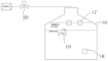
图2是本实用新型的组装设备间式洗车机的清水箱的供水原理的示意图。Fig. 2 is a schematic diagram of the water supply principle of the fresh water tank of the assembled equipment room car washing machine of the present invention.
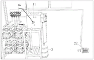
图3本实用新型的组装设备间式洗车机的内部局部结构示意图。Fig. 3 is a schematic diagram of the internal partial structure of the assembly room type car washer of the utility model.
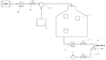
图4是本 实用新型的组装设备间式洗车机的洗液稀释后送出的原理示意图。Fig. 4 is a schematic diagram of the principle of sending out after the washing liquid of the assembled equipment room type car washing machine of the utility model is diluted.
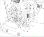
图5是本实用新型的组装设备间式洗车机的再一内部局部结构示意图。Fig. 5 is a schematic diagram of another internal partial structure of the car washer in the assembly room of the present invention.
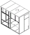
图6是本实用新型的组装设备间式洗车机的箱体的示意图。Fig. 6 is a schematic diagram of the cabinet of the assembled equipment room car washer of the present invention.
具体实施方式detailed description
以下结合附图和具体实施例对本实用新型作进一步详细说明。应当理解,此处所描述的具体实施例仅仅用以解释本实用新型,并不用于限定本实用新型。Below in conjunction with accompanying drawing and specific embodiment the utility model is described in further detail. It should be understood that the specific embodiments described here are only used to explain the utility model, and are not intended to limit the utility model.
如图1至图6所示,组装设备间式洗车机,包括矩形状框架结构的箱体100,所述箱体内设置有清水箱16、稀释洗车液水箱5、洗车液原液罐3、空气压缩机1以及用于输出高压清水的由多个柱塞泵2构成的柱塞泵组,所述清水箱位于所述箱体内一侧,所述稀释洗车液水箱通过支架7支撑位于所述清水箱的相对侧,所述洗车液原液罐位于所述支架7的一侧并近所述清水箱布置,所述支架与所述箱体的侧板之间布置柱塞泵组,所述稀释洗车液水箱的出液端第一增压泵4,所述第一增压泵的出口经过分水器27与多个车位支管连接,每个车位支管上连接一个常闭电磁阀9,该电磁阀下游通过一个三通接头23接来自所述空气压缩机1的高压气源以及一个工位的泡沫支管(未示出),泡沫支管通过管路再连接到水枪或是清洗枪(未示出),实现将气液混合的泡沫液经连接的泡沫支管并经水枪或清洗枪送出;所述稀释洗车液水箱5的进液端通过进液管路连接至洗车液原液罐3,该箱体100的一个侧板上开有多个孔,用于引出管路与箱体外的水枪或是清洗枪连接。As shown in Figures 1 to 6, the assembled equipment room type car washing machine includes a
在一个实施例下,所述清水箱16上设置水位传感器,所述水位传感器包括高水位传感器17、低水位传感器18,所述高水位传感为两个,互为备用;向所述清水箱供水的进水管上设有常开电磁阀20,出水端设置有浮球阀19,通过浮球阀及水位传感器配合实现对进水自动控制,实现了清水箱的自动补水控制。In one embodiment, a water level sensor is set on the
所述的清水箱自动补水,通过常开电磁阀、水位传感器两种组件配合,实现了与机械水位开关的协同作用,降低设备故障率,实现在机械水位开关失效时水箱水位满足要求时停止供水,水位低时补水的功能。The automatic replenishment of the clean water tank realizes the synergy with the mechanical water level switch through the cooperation of the two components of the normally open solenoid valve and the water level sensor, reduces the failure rate of the equipment, and realizes stopping the water supply when the water level of the water tank meets the requirements when the mechanical water level switch fails , The function of replenishing water when the water level is low.
其中,具体的是,在浮球阀水平位置之上安装两个高水位传感器。供水端为外部供水,外部供水通过管道连接常开电磁阀,最后连接浮球阀开关。正常情况下,补水至浮球阀开关时,供水由浮球阀切断,补水至正常水位线。浮球阀机械故障时,补水至高水位传感器时触发常开电磁阀供电开关,常开电磁阀关闭,供水停止;当清水箱内水位消耗至低于低水位传感器时,切断常开电磁阀电源,重新开始供水通过以上逻辑,解决了浮球开关故障时补水无法停止的缺陷,增强了设备稳定性。Wherein, specifically, two high water level sensors are installed above the horizontal position of the float valve. The water supply end is an external water supply, and the external water supply is connected to a normally open solenoid valve through a pipeline, and finally connected to a float valve switch. Under normal circumstances, when the water is supplied to the float valve switch, the water supply is cut off by the float valve, and the water is supplied to the normal water level. In case of mechanical failure of the float valve, when the water supply reaches the high water level sensor, the power supply switch of the normally open solenoid valve is triggered, the normally open solenoid valve is closed, and the water supply stops; The above logic is used to start water supply, which solves the defect that the water supply cannot be stopped when the float switch fails, and enhances the stability of the equipment.
其中,在一些实施例下,所述稀释洗车液水箱10的供液管路上自供水端至出液端依次设置有第二增压泵22、常闭电磁阀26、液体分配机10,所述液体分配体与第二增压泵22的出口、洗车液原液罐3的出口以及述稀释洗车液水箱5的入口通过管路相连接。所述第二增压泵22的入水口与清水箱的出水口相接,其中,所述稀释洗车液水箱10上设有水位传感器,包括高水位传感器11、低水位传感器12;所述高水位传感为两个,互为备用。Wherein, in some embodiments, a
通过稀释洗车液水箱上的水位传感器、第二增压泵、常闭电磁阀、液体分配机的组合,实现了洗车液原液自动稀释、稀释后洗车液自动补充的功能,降低了机器日常维护中洗车液的补充频次,从而降低了场地维护成本。Through the combination of the water level sensor on the water tank of the diluted car wash liquid, the second booster pump, the normally closed solenoid valve, and the liquid dispenser, the functions of automatic dilution of the original car wash liquid and automatic replenishment of the diluted car wash liquid are realized, reducing the daily maintenance of the machine. The frequency of replenishment of car wash liquid reduces the cost of site maintenance.
具体的,外部供水通过管道依次衔接第二增压泵、常闭电磁阀、液体分配机,稀释洗车液水箱;其中液体分配机衔接洗车液原液容器。Specifically, the external water supply is sequentially connected to the second booster pump, the normally closed solenoid valve, and the liquid dispenser through pipelines to dilute the car wash liquid water tank; wherein the liquid dispenser is connected to the original car wash liquid container.
当水位低于低位传感器时,常闭电磁阀开启,外部供水经第二增压泵加压泵至液体分配机,液体分配机内形成水流,水流带动液体分配机吸取洗车液原液,清水与洗车液原液在液体分配机中按设置比例混合,加注至稀释洗车液水箱中;稀释洗车液补充至高水位时,常闭电磁阀断电关闭,供水停止。通过以上逻辑,实现了洗车液原液自动稀释并补充至稀释洗车液水箱的功能,降低了设备维护频次,从而降低了设备维护成本。When the water level is lower than the low level sensor, the normally closed solenoid valve is opened, and the external water is pumped to the liquid dispenser through the second booster pump, and a water flow is formed in the liquid dispenser, and the water flow drives the liquid dispenser to absorb the original car wash solution, clean water and car wash The stock solution is mixed in the liquid dispenser according to the set ratio, and filled into the diluted car wash liquid tank; when the diluted car wash liquid is replenished to a high water level, the normally closed solenoid valve is powered off and the water supply stops. Through the above logic, the function of automatically diluting the original car wash solution and replenishing it to the water tank of the diluted car wash solution is realized, which reduces the frequency of equipment maintenance and thus reduces the cost of equipment maintenance.
其中,所述的液体分配机是一种可以将两种液体混合的设备,可调节混合比例,为现有技术设备,不再赘述。Wherein, the liquid dispensing machine is a device capable of mixing two liquids, and the mixing ratio can be adjusted, which is a prior art device and will not be described in detail here.
其中,所述箱体的门板15的内表面设置有控制箱14以及配电箱13,所述配电箱用于为设备的用电设备供电,所述控制箱用于控制设备的启停操作,可以连接触摸屏或是其它方便操作的机构或是人机界面设备等,实现控制操作进行洗车作业,此为现有技术,不再赘述。Wherein, the inner surface of the
其中,所述空气压缩机1的出气口接气体分流板8,所述气体分流板8具有一个气流入口,多个工位气流出口,气体分流板的出口按工位数安装常闭电磁阀24,所述的常闭电磁阀24通过气路支路接至一个所述三通接头23,每个三通接头的出液端连接到出液枪,实现多工位的出液,每一路均能单独控制。经过空气混合的泡沫液能够更丰沛、绵密。用户使用时,通过控制泡沫管路电磁阀开闭,由于管路中有增压泵输出稀释泡沫液,空压机提供压缩空气,电磁阀开启时,即可实现泡沫液的输出。Wherein, the air outlet of the
由于柱塞泵空转会导致设备烧毁,在柱塞水泵的压力开关不灵敏时,可能卡住的情况下,因此,一个实施例下,在每个柱塞泵2的供水端增加了流速传感器25,另外,每个柱塞泵的出水口28设置有水压传感器6,其中,所述出水口28通过水管连接到外部的水枪或清洗枪,这样,当柱塞泵处于工作状态时,流速传感器会传回流速信号,如低于设定值,则关闭柱塞泵电源,实现了对柱塞泵水压、流速的同时检测、控制,防止水泵空转烧毁,提高了设备稳定性。Since the idling of the plunger pump will cause the equipment to burn out, when the pressure switch of the plunger water pump is insensitive, it may be stuck. Therefore, in one embodiment, a
其中,所述每个柱塞泵2与供水管21通过清水送出分水器相连接,清水送出分水器的入水口与供水管之设置有控制阀29,清水送出分水器的多个分支出水管连接流速传感器25以及常闭电磁阀,并连接到对应的柱塞泵。通过控制阀29的开关,能控制清水通过柱塞泵输出或是送入到稀释洗车液水箱中的控制。Wherein, each of the
一些实施例下,通过设备间内按洗车工位数量配置的多个柱塞泵(水泵),通过水管连接外部的水枪或是清洗枪后,在清洗时,通过控制水泵的供水端常闭电磁阀的开启,即可接通供水,水泵开启,水泵出水,实现通过水枪采用高压清水洗车的功能。In some embodiments, through the multiple plunger pumps (water pumps) configured according to the number of car washing stations in the equipment room, after connecting the external water gun or cleaning gun through the water pipe, during cleaning, by controlling the water supply end of the water pump to normally close the solenoid When the valve is opened, the water supply can be connected, the water pump is turned on, and the water is discharged from the water pump, realizing the function of washing the car with high-pressure clean water through the water gun.
其中,在一些实施例下,所述的组装式设备间可以是由龙骨、地板、立柱、立板、屋顶龙骨、屋顶构成,具有开启的门体,可以全部采用标准化后的金属零件组装形成,可根据工位数量进行设备间面积、形状的调整。Wherein, in some embodiments, the assembled equipment room may be composed of keels, floors, columns, vertical plates, roof keels, and roofs, and has an open door, which may be assembled and formed by standardized metal parts. The area and shape of the equipment room can be adjusted according to the number of stations.
以上显示和描述了本实用新型的基本原理和主要特征和本实用新型的优点,对于本领域技术人员而言,显然本实用新型不限于上述示范性实施例的细节,而且在不背离本实用新型的精神或基本特征的情况下,能够以其他的具体形式实现本实用新型;The basic principles and main features of the utility model and the advantages of the utility model have been shown and described above. For those skilled in the art, it is obvious that the utility model is not limited to the details of the above-mentioned exemplary embodiments, and without departing from the utility model In the case of the spirit or basic features, the utility model can be realized in other specific forms;
因此,无论从哪一点来看,均应将实施例看作是示范性的,而且是非限制性的,本实用新型的范围由所附权利要求而不是上述说明限定,因此旨在将落在权利要求的等同要件的含义和范围内的所有变化囊括在本实用新型内。Therefore, no matter from all points of view, the embodiments should be regarded as exemplary and non-restrictive, and the scope of the present invention is defined by the appended claims rather than the above description, so it is intended to be included in the claims All changes within the meaning and range of equivalents of the required elements are included in the present invention.
此外,应当理解,虽然本说明书按照实施方式加以描述,但并非每个实施方式仅包含一个独立的技术方案,说明书的这种叙述方式仅仅是为清楚起见,本领域技术人员应当将说明书作为一个整体,各实施例中的技术方案也可以经适当组合,形成本领域技术人员可以理解的其他实施方式。In addition, it should be understood that although this specification is described according to implementation modes, not each implementation mode only contains an independent technical solution, and this description in the specification is only for clarity, and those skilled in the art should take the specification as a whole , the technical solutions in the various embodiments can also be properly combined to form other implementations that can be understood by those skilled in the art.
Claims (5)
Priority Applications (1)
| Application Number | Priority Date | Filing Date | Title |
|---|---|---|---|
| CN202222879526.4U CN218316632U (en) | 2022-10-31 | 2022-10-31 | Assembled equipment room type car washer |
Applications Claiming Priority (1)
| Application Number | Priority Date | Filing Date | Title |
|---|---|---|---|
| CN202222879526.4U CN218316632U (en) | 2022-10-31 | 2022-10-31 | Assembled equipment room type car washer |
Publications (1)
| Publication Number | Publication Date |
|---|---|
| CN218316632U true CN218316632U (en) | 2023-01-17 |
Family
ID=84827183
Family Applications (1)
| Application Number | Title | Priority Date | Filing Date |
|---|---|---|---|
| CN202222879526.4U Expired - Fee Related CN218316632U (en) | 2022-10-31 | 2022-10-31 | Assembled equipment room type car washer |
Country Status (1)
| Country | Link |
|---|---|
| CN (1) | CN218316632U (en) |
-
2022
- 2022-10-31 CN CN202222879526.4U patent/CN218316632U/en not_active Expired - Fee Related
Similar Documents
| Publication | Publication Date | Title |
|---|---|---|
| CN218316632U (en) | Assembled equipment room type car washer | |
| CN205344848U (en) | Possesses self -service car washer of internet intelligence that fills electric pile function | |
| CN103925831A (en) | Externally-connected cleaning device for air conditioner heat exchanger | |
| CN201002081Y (en) | Air water pulse cleaning equipment | |
| WO2024037538A1 (en) | Flushing system and toilet device | |
| CN105392367A (en) | Device for dispensing yeast in a bakery and system for dispensing yeast in a bakery | |
| CN209274591U (en) | A kind of pneumatic control water system for the vehicles | |
| CN203781826U (en) | Railway vacuum sewage discharging system | |
| CN105857261B (en) | A self-service car washing machine | |
| JP3244077U (en) | Compressor offline cleaning system | |
| CN209366108U (en) | Self-help car washer foam generating system and Self-help car washer | |
| CN203893742U (en) | On-line condenser cleaning device | |
| CN211844372U (en) | Emptying device of self-service car washer and novel self-service car washer | |
| CN216805383U (en) | A distributed self-service washing station | |
| CN201321634Y (en) | Energy-saving water supply device | |
| CN211120157U (en) | Automatic timing blowing liquid return device for unit shutdown | |
| CN105667458B (en) | For more people intelligent self-service car washer used at the same time | |
| CN207466671U (en) | High speed motor car toilet drainage cleaning device | |
| CN111152760A (en) | Emptying device of self-service car washer and novel self-service car washer | |
| CN219283688U (en) | Buffer water tank integrated module for heat pump | |
| CN217523931U (en) | Cigarette making machine equipment and glue supply device thereof | |
| CN222474456U (en) | Function indicating device of aircraft sanitation system | |
| CN216916230U (en) | Marine high-pressure window washing system | |
| CN216572202U (en) | A high pressure water mist dust removal system | |
| CN218805727U (en) | A multifunctional car washing machine |
Legal Events
| Date | Code | Title | Description |
|---|---|---|---|
| GR01 | Patent grant | ||
| GR01 | Patent grant | ||
| CF01 | Termination of patent right due to non-payment of annual fee | ||
| CF01 | Termination of patent right due to non-payment of annual fee |
Granted publication date: 20230117 |