CN218312537U - Equipment for rough grinding of surface of saw blade - Google Patents
Equipment for rough grinding of surface of saw blade Download PDFInfo
- Publication number
- CN218312537U CN218312537U CN202222613175.2U CN202222613175U CN218312537U CN 218312537 U CN218312537 U CN 218312537U CN 202222613175 U CN202222613175 U CN 202222613175U CN 218312537 U CN218312537 U CN 218312537U
- Authority
- CN
- China
- Prior art keywords
- base
- motor
- cylinder
- workstation
- saw bit
- Prior art date
- Legal status (The legal status is an assumption and is not a legal conclusion. Google has not performed a legal analysis and makes no representation as to the accuracy of the status listed.)
- Active
Links
Images


Abstract
The utility model discloses an equipment for saw bit surface corase grind processing, including base and control box, one side of base surface is fixed with the lift post, the cooperation of the lift post outside has the crane, there is elevating system at the top of lift post, the crane tip of keeping away from the lift post is equipped with positioning mechanism, the base of positioning mechanism below is equipped with the workstation, the center on workstation surface is equipped with hexagonal cooperation piece, the base surface in the workstation outside is equipped with first cylinder fixing base, first cylinder fixing base fit in has first cylinder, the top surface of first cylinder fixing base is equipped with the slide rail, the middle part spout fit in of slide rail has the slip strip, the tip cooperation of slip strip has the mill, this equipment passes through positioning mechanism and elevating system's combined action and fixes the saw bit on the workstation steadily, avoid saw bit vibrations and saw bit offset to influence the shaping effect of recess or sawtooth on the saw bit, thereby guarantee the corase grind processing effect on saw bit surface.
Description
Technical Field
The utility model relates to a saw bit production technical field specifically is an equipment that is used for saw bit surface corase grind processing.
Background
The saw blade can involve the processing of the positions such as grooves, saw teeth and the like in the production process, and some sharp barbs can appear on the end surface of the saw blade where the positions are located, and the barbs are easy to cause harm to people and influence the aesthetic property of the saw blade; in this regard, some devices for rough grinding are designed to handle barbs on both sides of the saw blade.
The rough grinding machine is accomplished through saw bit surface and the wheel contact of polishing to the both sides surface coarse grinding processing of saw bit, in the coarse grinding course of working, if there is the defect in the rigidity effect of saw bit, can produce vibrations easily when saw bit and the roller contact of polishing, the condition that causes saw bit offset appears, saw bit or recess isotructure of saw bit border department contact with the roller of polishing easily when vibrations to cause the condition that the saw bit collapses to be bad or groove deformation to appear.
Along with the continuous improvement of saw bit coarse grinding processing requirement, the mill size that saw bit coarse grinding processing adopted can cause certain influence to saw bit coarse grinding processing's efficiency, and mill mounted position on the rough grinding machine need reserve sufficient space and carry out the mill installation of different size specifications.
Therefore, it is necessary to design an apparatus for rough grinding of the surface of the saw blade.
SUMMERY OF THE UTILITY MODEL
The utility model discloses to above-mentioned technique is not enough, provides one kind through positioning mechanism and elevating system's combined action with the saw bit fix on the workstation steadily, avoid saw bit vibrations and saw bit offset to influence the shaping effect of saw bit upper groove or sawtooth to guarantee the equipment of the corase grind processing effect on saw bit surface.
In order to achieve the above purpose, the utility model discloses a following technical scheme realizes:
the utility model provides an equipment for saw bit surface corase grind processing, includes base and control box, one side on base surface is fixed with the lift post, the cooperation of the lift post outside has the crane, there is elevating system at the top of lift post, keeps away from the crane tip of lift post is equipped with positioning mechanism, the base of positioning mechanism below is equipped with the workstation, the center on workstation surface is equipped with hexagonal cooperation piece, the base surface in the workstation outside is equipped with first cylinder fixing base, first cylinder fixing base fit in has first cylinder, the top surface of first cylinder fixing base is equipped with the slide rail, the middle part spout fit in of slide rail has the slip, the tip cooperation of slip has the mill, the drive end of first cylinder has the connecting plate through the articulate, the top of connecting plate is fixed in the slip bottom.
Further, elevating system includes first motor and lead screw, the top and the bottom of lift post are equipped with first backup pad and second backup pad respectively, first backup pad surface is equipped with first motor, the drive end of first motor is equipped with the lead screw, the lead screw runs through first backup pad and second backup pad, the screw-nut and the crane lateral wall of lead screw are connected.
Further, positioning mechanism includes second motor, main shaft head, main shaft and location end, one side of crane tip is connected with second motor fixing base, the cooperation of second motor is in second motor fixing base, the main shaft head cooperation is in the first mating holes of crane tip, the main shaft passes through the bearing cooperation in the main shaft head and both ends all extend to outside the main shaft head from top to bottom, the drive end of second motor and the upper end of main shaft all are equipped with the belt pulley, two the belt pulley between connect through the drive belt, the location end passes through the bottom of screw-thread fit's mode cooperation at the main shaft, the bottom of location end is equipped with the second mating holes that the shape is the same with hexagonal cooperation lump shape form.
Further, the bottom of workstation is equipped with rotary device, be equipped with second cylinder fixing base in the base of rotary device below, second cylinder fixing base is equipped with the second cylinder, the second cylinder runs through the top surface of base and is connected with rotary device's stiff end.
Further, the sliding strip is equipped with that a plurality of is the inline and the same screw hole in interval, mill and connecting plate are all fixed in the sliding strip bottom through the cooperation of screw and screw hole.
The utility model has the advantages that:
the device stably fixes the saw blade on the workbench through the combined action of the positioning mechanism and the lifting mechanism, so that the vibration of the saw blade and the position deviation of the saw blade are prevented from influencing the forming effect of grooves or saw teeth on the saw blade, and the rough grinding processing effect of the surface of the saw blade is ensured; when the grinding disc with different specifications is required to be replaced, the space can be vacated for the installation of the grinding disc with larger size by adjusting the fixed position of the connecting plate, so that the requirements of coarse grinding and processing of different saw blades are met.
Drawings
Fig. 1 is a schematic structural view of the apparatus.
Fig. 2 is a partially enlarged view of a portion a in fig. 1.
Fig. 3 is a schematic structural view of the lifting mechanism.
Fig. 4 is a schematic structural view of the positioning mechanism.
FIG. 5 is a schematic view of the positioning tip.
Fig. 6 is a schematic structural view of the table.
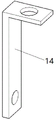
FIG. 7 is a schematic view of the connection plate
In the figure, 1, a base; 2. a control box; 3. a lifting column; 4. a lifting frame; 5. a lifting mechanism; 6. a positioning mechanism; 7. a work table; 8. a hexagonal mating block; 9. a first cylinder fixing seat; 10. a first cylinder; 11. a slide rail; 12. a slide bar; 13. a grinding disc; 14. a connecting plate; 15. a first motor; 16. a screw rod; 17. a first support plate; 18. a second support plate; 19. a feed screw nut; 20. a second motor; 21. a spindle head; 22. a main shaft; 23. positioning an end head; 24. a second motor fixing seat; 25. a belt pulley; 26. a transmission belt; 27. a mating hole; 28. a rotating device; 29. a second cylinder fixing seat; 30. a second cylinder; 31. a screw hole; 32. a second mating hole.
Detailed Description
As shown in fig. 1 to 7, an apparatus for rough grinding of the surface of a saw blade includes a base 1 and a control box 2, a lifting column 3 is fixed on one side of the surface of the base 1, a lifting frame 4 is matched with the outer side of the lifting column 3, a lifting mechanism 5 is arranged at the top of the lifting column 3, a positioning mechanism 6 is arranged at the end of the lifting frame 4 far away from the lifting column 3, a workbench 7 is arranged on the base 1 below the positioning mechanism 6, a hexagonal matching block 8 is arranged at the center of the surface of the workbench 7, a first cylinder fixing seat 9 is arranged on the surface of the base 1 outside the workbench 7, a first cylinder 10 is matched with the first cylinder fixing seat 9, a slide rail 11 is arranged on the top surface of the first cylinder fixing seat 9, a slide bar 12 is matched with the slide rail 11 in a sliding groove in the middle part, a grinding disc 13 is matched with the end of the slide bar 12, a driving end of the first cylinder 10 is connected with a connecting plate 14 through a joint, and the top end of the connecting plate 14 is fixed at the bottom end of the slide bar 12.
The lifting mechanism 5 comprises a first motor 15 and a screw rod 16, a first supporting plate 17 and a second supporting plate 18 are respectively arranged at the top end and the bottom end of the lifting column 3, the first motor 15 is arranged on the surface of the first supporting plate 17, the screw rod 16 is arranged at the driving end of the first motor 15, the screw rod 16 penetrates through the first supporting plate 17 and the second supporting plate 18, and a screw rod nut 19 of the screw rod 16 is connected with the side wall of the lifting frame 4.
The bottom of workstation 7 is equipped with rotary device 28, be equipped with second cylinder fixing base 29 in the base 1 of rotary device 28 below, second cylinder fixing base 29 is equipped with second cylinder 30, second cylinder 30 runs through the top surface of base 1 and is connected with rotary device 28's stiff end.
The control box 2 is used for controlling electric components on the equipment to work, and the saw blade is placed on the surface of the workbench 7 along the matching direction of the saw blade center hole and the hexagonal matching block 8; the first motor drives the screw rod 16 to rotate, and the screw rod nut 19 drives the lifting frame 4 to move up and down on the lifting column 3, so as to drive the positioning mechanism 6 to move up and down; under the driving of the lifting mechanism 5, the positioning end 23 moves to the position above the saw blade, along with the further descending of the positioning end 23, the hexagonal matching block 8 is gradually matched into the second matching hole 32 for positioning, when the bottom surface of the positioning end 23 is abutted to the surface of the saw blade, the positioning end 23 is tightly pressed on the surface of the saw blade, so that the saw blade is fixed on the surface of the workbench 7, the influence of the vibration and the position deviation of the saw blade on the forming effect of the groove or the saw blade on the saw blade is avoided, and the rough grinding processing effect of the surface of the saw blade is ensured; the second motor 20 drives the main shaft 22 to rotate, the workbench 7 and the saw blade also rotate along with the main shaft, then the grinding disc 13 is driven by the first air cylinder 10 to move to the position above the saw blade, after the grinding disc 13 moves to the position above the saw blade, the position of the workbench 7 is adjusted by the first motor and the second air cylinder 30 together, so that the effect of adjusting the height of the saw blade is achieved, the requirements of rough grinding and machining of the saw blade with different thicknesses are met, the saw blade is in surface contact with the grinding disc 13 to perform rough grinding and machining on the surface, and barbs on the two side surfaces of the saw blade are ground flat by the grinding disc 13; when the grinding disc 13 with different specifications and sizes is required to be replaced, the adjusting connecting plate 14 is fixed at the position of the screw hole 31 at the bottom of the sliding strip 12, so that a space is reserved for the grinding disc 13 with the larger installation size, and the requirement of rough grinding of saw blades with different diameters and sizes is met.
Furthermore, it should be understood that although the present description refers to embodiments, not every embodiment may contain only a single embodiment, and such description is for clarity only, and those skilled in the art should integrate the description, and the embodiments may be combined as appropriate to form other embodiments understood by those skilled in the art.
Claims (5)
1. The utility model provides an equipment for saw bit surface corase grind processing, includes base and control box, its characterized in that, one side on base surface is fixed with the lift post, the cooperation of the lift post outside has the crane, there is elevating system at the top of lift post, keeps away from the crane tip of lift post is equipped with positioning mechanism, the base of positioning mechanism below is equipped with the workstation, the center on workstation surface is equipped with hexagonal cooperation piece, the base surface in the workstation outside is equipped with first cylinder fixing base, first cylinder fixing base fit has first cylinder, the top surface of first cylinder fixing base is equipped with the slide rail, the middle part spout fit in of slide rail has the slip strip, the tip cooperation of slip strip has the mill, the drive end of first cylinder has the connecting plate through articulate, the top of connecting plate is fixed in the slip strip bottom.
2. The device as claimed in claim 1, wherein the lifting mechanism comprises a first motor and a lead screw, the top and bottom ends of the lifting column are respectively provided with a first support plate and a second support plate, the surface of the first support plate is provided with the first motor, the driving end of the first motor is provided with the lead screw, the lead screw penetrates through the first support plate and the second support plate, and a lead screw nut of the lead screw is connected with the side wall of the lifting frame.
3. The device for rough grinding of the surface of the saw blade according to claim 1, wherein the positioning mechanism comprises a second motor, a spindle head, a spindle and a positioning end head, one side of the end part of the lifting frame is connected with a second motor fixing seat, the second motor is matched in the second motor fixing seat, the spindle head is matched in a first matching hole in the end part of the lifting frame, the spindle is matched in the spindle head through a bearing, the upper end and the lower end of the spindle head both extend out of the spindle head, belt pulleys are arranged at the driving end of the second motor and the upper end of the spindle, the two belt pulleys are connected through a transmission belt, the positioning end head is matched at the bottom end of the spindle in a threaded matching manner, and a second matching hole with the same shape as a hexagonal matching block is arranged at the bottom end of the positioning end head.
4. The device for roughly grinding the surface of the saw blade as claimed in claim 1, wherein the bottom end of the worktable is provided with a rotating device, a second cylinder fixing seat is arranged in the base below the rotating device, the second cylinder fixing seat is provided with a second cylinder, and the second cylinder penetrates through the top surface of the base and is connected with the fixing end of the rotating device.
5. The device as claimed in claim 1, wherein the slide bar has a plurality of screw holes arranged in a straight line and spaced at the same intervals, and the grinding disc and the connecting plate are fixed to the bottom end of the slide bar by the screws and the screw holes.
Priority Applications (1)
| Application Number | Priority Date | Filing Date | Title |
|---|---|---|---|
| CN202222613175.2U CN218312537U (en) | 2022-09-30 | 2022-09-30 | Equipment for rough grinding of surface of saw blade |
Applications Claiming Priority (1)
| Application Number | Priority Date | Filing Date | Title |
|---|---|---|---|
| CN202222613175.2U CN218312537U (en) | 2022-09-30 | 2022-09-30 | Equipment for rough grinding of surface of saw blade |
Publications (1)
| Publication Number | Publication Date |
|---|---|
| CN218312537U true CN218312537U (en) | 2023-01-17 |
Family
ID=84820799
Family Applications (1)
| Application Number | Title | Priority Date | Filing Date |
|---|---|---|---|
| CN202222613175.2U Active CN218312537U (en) | 2022-09-30 | 2022-09-30 | Equipment for rough grinding of surface of saw blade |
Country Status (1)
| Country | Link |
|---|---|
| CN (1) | CN218312537U (en) |
-
2022
- 2022-09-30 CN CN202222613175.2U patent/CN218312537U/en active Active
Similar Documents
| Publication | Publication Date | Title |
|---|---|---|
| CN110732919A (en) | Hole repairing device for stamping parts | |
| CN105382659A (en) | Automatic grinding machine | |
| CN201960139U (en) | Centerless lathe adopting electric spindle and realizing automatic centering of cylindrical rod and pipe material | |
| CN205166610U (en) | Automatic grinding machine | |
| CN107790823A (en) | A kind of cutting machine for metal materials of good fixing effect | |
| CN104786379A (en) | Angle adjusting device of multi-wire cutting machine workpiece installing table | |
| CN114769740A (en) | Gear machining machine tool with burr removing structure | |
| CN218312537U (en) | Equipment for rough grinding of surface of saw blade | |
| CN202070828U (en) | Sawtooth radial clearance angle grinding device | |
| CN214351401U (en) | Aluminium alloy cutting fracture processing apparatus | |
| CN112453901B (en) | Gear edge grinding, polishing and marking all-in-one machine and using method thereof | |
| CN211163364U (en) | Multifunctional automatic grinding machine | |
| CN113752124A (en) | Grinding die and optical lens grinder | |
| CN109015172B (en) | Long-shaft workpiece deburring equipment for automobile | |
| CN206999168U (en) | Moveable wood craft machines binder feed device | |
| CN2199008Y (en) | Lapping machine for arc stone material | |
| CN215903280U (en) | Metal word shell wire drawing equipment of polishing | |
| CN107756233B (en) | Grinding device for quartz crystal oscillator wafer production and processing | |
| CN216913280U (en) | Lower moving type abrasive belt grinding machine | |
| CN214923014U (en) | Supporting structure of glass cup blank grinding device | |
| CN219945760U (en) | Roll grinder pinch roll bracket device | |
| CN219617358U (en) | Deburring device for bearing pedestal forging | |
| CN209902804U (en) | High-efficient milling cutter sharpedge grinding machine | |
| CN211388014U (en) | Device for reducing or eliminating grinding vibration marks | |
| CN219542540U (en) | Cooling dust removal chamfering machine |
Legal Events
| Date | Code | Title | Description |
|---|---|---|---|
| GR01 | Patent grant | ||
| GR01 | Patent grant |