CN218274854U - Bottom protection plate, box body, battery and electric equipment - Google Patents
Bottom protection plate, box body, battery and electric equipment Download PDFInfo
- Publication number
- CN218274854U CN218274854U CN202222640319.3U CN202222640319U CN218274854U CN 218274854 U CN218274854 U CN 218274854U CN 202222640319 U CN202222640319 U CN 202222640319U CN 218274854 U CN218274854 U CN 218274854U
- Authority
- CN
- China
- Prior art keywords
- layer
- battery
- surface layer
- buffer layer
- vertical direction
- Prior art date
- Legal status (The legal status is an assumption and is not a legal conclusion. Google has not performed a legal analysis and makes no representation as to the accuracy of the status listed.)
- Active
Links
Images


Classifications
-
- Y—GENERAL TAGGING OF NEW TECHNOLOGICAL DEVELOPMENTS; GENERAL TAGGING OF CROSS-SECTIONAL TECHNOLOGIES SPANNING OVER SEVERAL SECTIONS OF THE IPC; TECHNICAL SUBJECTS COVERED BY FORMER USPC CROSS-REFERENCE ART COLLECTIONS [XRACs] AND DIGESTS
- Y02—TECHNOLOGIES OR APPLICATIONS FOR MITIGATION OR ADAPTATION AGAINST CLIMATE CHANGE
- Y02E—REDUCTION OF GREENHOUSE GAS [GHG] EMISSIONS, RELATED TO ENERGY GENERATION, TRANSMISSION OR DISTRIBUTION
- Y02E60/00—Enabling technologies; Technologies with a potential or indirect contribution to GHG emissions mitigation
- Y02E60/10—Energy storage using batteries
Abstract
The application relates to the technical field of batteries, in particular to a bottom protection plate, a box body, a battery and electric equipment. The utility model provides a bottom protective plate is used for constituting the box of battery, and bottom protective plate includes the buffer layer, and the buffer layer is equipped with a plurality of trompils that extend along first direction, and wherein, first direction is crossing with vertical direction. According to the end backplate of this application, through setting up the buffer layer, can reduce the deformation that external shock caused the backplate at the bottom effectively, thereby reduce or avoid causing the damage of the interior cooling plate of battery box or the deformation of electric core, and simultaneously, further set up the trompil that extends along the first direction in the buffer layer, and the extending direction of trompil intersects with the first direction, when the backplate receives the impact at the bottom, radial compression through the trompil is out of shape and can further reduce the deformation that strikes and cause the backplate at the bottom, thereby reduce or avoid causing the damage of the interior cooling plate of battery box or the deformation of electric core, guarantee the security and the reliability that the battery used, guarantee driving safety.
Description
Technical Field
The application relates to the technical field of batteries, in particular to a bottom protection plate, a box body, a battery and electric equipment.
Background
In recent years, with economic development, battery technology has been widely used in various fields, particularly in the field of new energy vehicles. At present, new energy vehicles have caused great impact on conventional fuel vehicles. The battery is used as a core component of a new energy vehicle and plays a vital role in the development process of the new energy vehicle.
The existing new energy automobile battery is mostly arranged at the bottom of an automobile frame, so that the bottom of the battery is very close to the ground, but the following problems exist in the later driving process: the power battery protection structure is lacked in current new energy automobile bottom or protection structure performance is not enough, can't resist the vehicle and strike through great or high-speed stone that bad road conditions produced, and then leads the cooling plate damage or the electric core deformation of power battery bottom to influence driving safety.
SUMMERY OF THE UTILITY MODEL
In view of the defects existing in the prior art, the present application aims to provide a bottom protection plate, a box body, a battery and an electric device, which can effectively solve the problem of damage of a cooling plate at the bottom of a power battery or deformation of a battery cell.
A first aspect of the present application discloses a floor sheathing for constituting a case of a battery, the floor sheathing including:
the buffer layer, the buffer layer is equipped with a plurality of trompils that extend along first direction, wherein, first direction is crossing with vertical direction.
According to the end backplate of this application, through setting up the buffer layer, can reduce the deformation that external shock caused the backplate at the bottom effectively, thereby reduce or avoid causing the damage of the interior cooling plate of battery box or the deformation of electric core, and simultaneously, further set up the trompil that extends along the first direction in the buffer layer, and the extending direction of trompil intersects with the first direction, when the backplate receives the impact at the bottom, radial compression through the trompil is out of shape and can further reduce the deformation that strikes and cause the backplate at the bottom, thereby reduce or avoid causing the damage of the interior cooling plate of battery box or the deformation of electric core, guarantee the security and the reliability that the battery used, guarantee driving safety.
In some embodiments of the present invention, the bottom guard plate further includes a first surface layer and a second surface layer, and the first surface layer, the buffer layer and the second surface layer are sequentially attached to each other along a vertical direction. Through setting up first superficial layer and second superficial layer to the both sides of buffer layer are located along vertical direction respectively to first superficial layer and second superficial layer, can play supporting role and guard action to the buffer, prevent buffer layer and other part contact or friction, avoid the buffer layer to take place to damage.
In some embodiments of the present invention, the first surface layer is an insulating material layer and is disposed toward the battery cell in the case. The first surface layer is arranged to be an insulating material layer and arranged towards the battery core in the box body, so that the conductive connection between the battery core and the first surface layer can be effectively isolated, and the conductive phenomenon between the battery core and the first surface layer is prevented.
In some embodiments of the invention, the second surface layer is a rigid material layer and is intended to be arranged towards the outside of the box. Set up the second superficial layer into the rigidity material layer to the outside setting towards the box, the second superficial layer receives external impact at first, and can absorb most impact energy, then the buffer layer cushions remaining energy dispersion, whole absorption even, thereby reduces or avoids causing the damage of cooling plate or the deformation of electricity core in the box.
In some embodiments of the present invention, the ratio of the thickness of the first surface layer, the buffer layer, and the second surface layer in the vertical direction is in the range of 1:1:1 to 1:8:4, in the above range. Through setting up first superficial layer, buffer layer and second superficial layer according to above-mentioned thickness ratio, can guarantee the impact-resistant effect of second superficial layer effectively to and the effect of the absorption impact of buffer layer.
In some embodiments of the invention, the first direction is a horizontal direction. The holes are arranged along the horizontal direction, so that the holes can be extruded and deformed to the maximum extent along the radial direction, and the impact absorption capacity of the buffer layer is improved.
In some embodiments of the present invention, the buffer layer is an elastic material layer. The elastic material layer has good deformability, so that the impact of the bottom protection plate is absorbed, and meanwhile, the elastic material layer has good deformation recovery capability and can recover to the original state after losing the impact effect, so that the elastic material layer is used for absorbing the impact of the bottom protection plate again.
In some embodiments of the present invention, the elastic material layer is at least one of a silicone rubber layer or a polyurethane layer, and the two side surfaces of the elastic material layer along the vertical direction are respectively bonded to the first surface layer and the second surface layer. The elastic material layer is set to be at least one of a silicon rubber layer or a polyurethane layer, the silicon rubber or the polyurethane can be directly adhered to one of the first surface layer and the second surface layer due to the fact that the silicon rubber or the polyurethane has viscosity, then the other one of the first surface layer and the second surface layer is adhered to the other side of the elastic material layer, the first surface layer and the second surface layer are extruded to form a buffer layer, and finally the bottom protection plate is formed.
In some embodiments of the present invention, the elastic material layer is a rubber layer, one side of the rubber layer in the vertical direction is bonded to the first surface layer through the first adhesive layer, and the other side of the rubber layer in the vertical direction is bonded to the second surface layer through the second adhesive layer. The elastic material layer is arranged as a rubber layer, and the laminated structure formed by the rubber can be respectively bonded with the first surface layer and the second surface layer through bonding layers, so that the bottom guard plate is formed.
In some embodiments of the present invention, the first adhesive layer has a thermal conductivity greater than or equal to a thermal conductivity of the second adhesive layer. Because first tie coat is used for connecting first superficial layer and elastic material layer, and first superficial layer sets up towards the electric core in the box, the battery is at the during operation, can produce a large amount of heats in the box, in order to facilitate the inside to the box dispel the heat, the coefficient of heat conductivity that is greater than or equal to the second tie coat with first tie coat sets up, thereby the inside heat of the box of being convenient for dispels the heat through first superficial layer and first tie coat, the coefficient of heat conductivity that the coefficient of heat conductivity is less than or equal to first tie coat sets up simultaneously, can prevent that outside high temperature from passing through the inside of second tie coat conduction to the box, guarantee the normal work of electric core in the box.
In some embodiments of the present invention, the opening is a through hole that penetrates the buffer layer; and/or the opening is a blind hole extending into the buffer layer. The open hole can be arranged to be a through hole and/or a blind hole, and the through hole and the blind hole can be effectively compressed and deformed along the radial direction, so that the deformation of the bottom guard plate caused by external impact is reduced.
In some embodiments of the present invention, the range of porosity of the plurality of openings on the buffer layer is greater than 0 and less than 40%. The range value of the porosity is set to be 0 to 40%, and the contractible deformation and recoverable characteristics of the buffer layer can be effectively exerted.
A second aspect of the present invention provides a case for constituting a battery, the case having the bottom guard plate of any one of the above.
In some embodiments of the present invention, the bottom guard is disposed outside the box, and the first surface layer of the bottom guard is connected to the bottom plate of the box. The bottom plate of first superficial layer and box links to each other to locate the outside of box with end backplate, can cross and cushion the bottom plate effectively through end backplate, guarantee simultaneously that the trompil on the backplate locates the outside of box, thereby can extrude the outside of box, the compression deformation of the trompil of being convenient for with the gas in the trompil when the trompil warp.
In some embodiments of the present invention, the bottom plate is a bottom plate of the box, the first surface layer of the bottom plate is connected to a side plate of the box, and the opening is communicated with the outside of the box. The backplate is the bottom plate of box at the bottom to link to each other the first superficial layer of backplate at the bottom with the curb plate of box, be about to buffer layer and second superficial layer locate the outside of box, thereby make the outside of trompil and box be linked together, thereby can extrude the outside to the box with the gas in the trompil when the trompil warp, the compressive deformation of the trompil of being convenient for.
A third aspect of the present invention provides a battery having the box of any one of the above.
The fourth aspect of the present invention provides an electric device, wherein the electric device has the above battery.
The above description is only an overview of the technical solutions of the present application, and the present application may be implemented in accordance with the content of the description so as to make the technical means of the present application more clearly understood, and the detailed description of the present application will be given below in order to make the above and other objects, features, and advantages of the present application more clearly understood.
Drawings
Various other advantages and benefits will become apparent to those of ordinary skill in the art upon reading the following detailed description of the preferred embodiments. The drawings are only for purposes of illustrating the preferred embodiments and are not to be construed as limiting the application. Also, like reference numerals are used to refer to like parts throughout the drawings. In the drawings:
FIG. 1 is a schematic structural diagram of a vehicle provided in an embodiment of the present application;
fig. 2 is an exploded schematic view of a battery according to an embodiment of the present disclosure;
fig. 3 is a schematic structural view of a battery module according to an embodiment of the present disclosure;
fig. 4 is an exploded structural schematic diagram of a battery cell provided in an embodiment of the present application;
FIG. 5 is a schematic structural view of a bottom shield according to an embodiment of the present disclosure;
FIG. 6 is an exploded view of the bottom shield according to one embodiment of the present disclosure;
FIG. 7 is an enlarged view of the portion A of the bottom cover plate according to an embodiment of the present disclosure;
FIG. 8 is a schematic view of a cross-sectional view B-B of a bottom shield according to an embodiment of the present disclosure;
FIG. 9 is a schematic view of a cross-sectional view taken along line C-C of a bottom shield according to an embodiment of the present disclosure.
The reference numbers in the detailed description are as follows:
1: a vehicle;
10: battery, 11: controller, 12: a motor;
20: battery module, 21: battery cell, 211: end cap, 212: a housing, 213: electrode assembly, 214: an electrode terminal;
30: case, 31: first portion, 32: second portion, 321: bottom plate, 322: a side plate;
40: bottom guard plate, 41: buffer layer, 411: opening a hole, 42: first surface layer, 43: a second surface layer.
Detailed Description
Embodiments of the present invention will be described in detail below with reference to the accompanying drawings. The following embodiments are merely used to more clearly illustrate the technical solutions of the present application, and therefore, the following embodiments are only used as examples, and the scope of the present application is not limited thereby.
It should be noted that technical terms or scientific terms used in the embodiments of the present application should be given ordinary meanings as understood by those skilled in the art to which the embodiments of the present application belong, unless otherwise specified.
In the description of the embodiments of the present application, the terms "center", "longitudinal", "lateral", "length", "width", "thickness", "upper", "lower", "front", "rear", "left", "right", "vertical", "horizontal", "top", "bottom", "inner", "outer", "clockwise", "counterclockwise", "axial", "radial", "circumferential", and the like indicate orientations or positional relationships that are based on the orientations or positional relationships shown in the drawings, and are used only for convenience in describing the embodiments of the present application and for simplicity in description, but do not indicate or imply that the device or element being referred to must have a particular orientation, be constructed and operated in a particular orientation, and thus, should not be construed as limiting the embodiments of the present application.
Furthermore, the technical terms "first", "second", etc. are used for descriptive purposes only and are not to be construed as indicating or implying relative importance or implicitly indicating the number of technical features indicated. In the description of the embodiments of the present application, "a plurality" means two or more unless specifically defined otherwise.
In the description of the embodiments of the present application, unless otherwise explicitly specified or limited, the terms "mounted," "connected," "fixed," and the like are to be construed broadly, e.g., as meaning fixedly connected, detachably connected, or integrally formed; mechanical connection or electrical connection is also possible; either directly or indirectly through intervening media, either internally or in any other relationship. The specific meanings of the above terms in the embodiments of the present application can be understood by those of ordinary skill in the art according to specific situations.
In the description of the embodiments of the present application, unless otherwise explicitly specified or limited, a first feature "on" or "under" a second feature may be directly contacting the first and second features or indirectly contacting the first and second features through an intermediate. Also, a first feature "on," "over," and "above" a second feature may be directly or diagonally above the second feature, or may simply indicate that the first feature is at a higher level than the second feature. A first feature being "under," "below," and "beneath" a second feature may be directly under or obliquely under the first feature, or may simply mean that the first feature is at a lesser elevation than the second feature.
At present, the application of the power battery is more and more extensive from the development of market situation. The power battery is not only applied to energy storage power supply systems such as hydraulic power, firepower, wind power and solar power stations, but also widely applied to electric vehicles such as electric bicycles, electric motorcycles, electric automobiles and the like, and a plurality of fields such as military equipment and aerospace. Lithium ion batteries have been widely used in mobile and portable electrical appliances due to their advantages of high energy density, high average open circuit voltage, and long cycle life.
The inventor notices that the existing new energy automobile battery is mostly arranged at the bottom of an automobile frame, so that the bottom of the battery is very close to the ground, but the following problems exist in the later driving process: the bottom of the existing new energy automobile is lack of a power battery protection structure or the performance of the protection structure is insufficient, and the impact of a large or high-speed stone generated when the automobile passes through a severe road condition cannot be resisted, so that the cooling plate at the bottom of the power battery is damaged or an electric core is deformed, and the driving safety is influenced.
For solving the problem that the cooling plate of power battery bottom damages or electric core warp, the inventor research of this application discovers, sets up the buffer layer on the backplate at the bottom that constitutes the box to set up on the buffer layer along the trompil crossing with vertical direction, can reduce the deformation that external shock caused the backplate at the bottom effectively through buffer layer and trompil, thereby reduce or avoid causing the damage of cooling plate or the deformation of electric core in the battery box, guarantee the security and the reliability that the battery used, guarantee driving safety.
In view of the above, the inventors of the present application have conducted extensive studies to design a floor sheathing for constituting a case of a battery, and a cushioning layer provided with a plurality of openings extending in a first direction, wherein the first direction intersects with a vertical direction. According to the end backplate of this application, through setting up the buffer layer, can reduce the deformation that external shock caused the backplate at the bottom effectively, thereby reduce or avoid causing the damage of the interior cooling plate of battery box or the deformation of electric core, and simultaneously, further set up the trompil that extends along the first direction in the buffer layer, and the extending direction of trompil intersects with the first direction, when the backplate receives the impact at the bottom, radial compression through the trompil is out of shape and can further reduce the deformation that strikes and cause the backplate at the bottom, thereby reduce or avoid causing the damage of the interior cooling plate of battery box or the deformation of electric core, guarantee the security and the reliability that the battery used, guarantee driving safety.
The application provides a bottom guard plate, a box body comprising the bottom guard plate, a battery and electric equipment using the battery. The battery formed by the bottom guard plate and the box body can be suitable for various electric equipment using the battery, such as mobile phones, portable equipment, notebook computers, battery cars, electric toys, electric tools, electric vehicles, ships, spacecrafts and the like, for example, the spacecrafts comprise airplanes, rockets, space shuttles, spacecrafts and the like; the battery is used for providing electric energy for the electric equipment.
It should be understood that the technical solutions described in the embodiments of the present application are not limited to be applied to the above-described battery and electric equipment, but may be applied to all batteries including a box and electric equipment using the battery.
Fig. 1 is a schematic structural diagram of a vehicle 1 according to some embodiments of the present application. Fig. 2 is an exploded schematic view of a battery according to an embodiment of the present disclosure. Fig. 3 is a schematic structural view of a battery module 20 according to an embodiment of the present disclosure. Referring to fig. 1 to 3, the vehicle 1 may be a fuel-oil vehicle, a gas vehicle, or a new energy vehicle, and the new energy vehicle may be a pure electric vehicle, a hybrid electric vehicle, or a range-extended vehicle. The interior of the vehicle 1 is provided with a battery 10, and the battery 10 may be provided at the bottom or the head or the tail of the vehicle 1. The battery 10 may be used for power supply of the vehicle 1, and for example, the battery 10 may serve as an operation power source of the vehicle 1. The vehicle 1 may further include a controller 11 and a motor 12, the controller 11 being configured to control the battery 10 to power the motor 12, for example, for start-up, navigation, and operational power requirements while the vehicle 1 is traveling.
In some embodiments of the present application, the battery 10 may be used not only as an operation power source of the vehicle 1, but also as a driving power source of the vehicle 1, instead of or in part of fuel or natural gas, to provide driving power for the vehicle 1.
In order to meet different power requirements, the battery 10 may include a plurality of battery cells 21, and the battery cells 21 refer to the smallest unit constituting the battery module 20 or the battery pack. A plurality of the battery cells 21 may be connected in series and/or in parallel via electrode terminals to be applied to various applications. The battery 10 referred to in this application is a battery pack. The plurality of battery cells 21 may be connected in series, in parallel, or in series-parallel, where the series-parallel refers to a mixture of series connection and parallel connection. In the embodiment of the present application, the battery pack may be directly formed by a plurality of battery cells 21, or the battery module 20 may be formed first, and then the battery pack is formed by the battery module 20. A cooling plate (not shown in the figure) is disposed between two surfaces of the two battery cells 21 that are disposed opposite to each other in the vertical direction, specifically, a cooling plate may be disposed between two large surfaces or between two side surfaces, so as to cool the battery cells 21.
As shown in fig. 2 and 3 in conjunction, the battery 10 may include a plurality of battery modules 20 and a case 30, and the plurality of battery modules 20 are received inside the case 30. The case 30 is used to accommodate the battery cells 21 or the battery module 20 to prevent liquid or other foreign matter from affecting the charging or discharging of the battery cells 21. The box body 30 may be a simple three-dimensional structure such as a single rectangular parallelepiped, a single cylinder, or a single sphere, or may be a complex three-dimensional structure formed by combining simple three-dimensional structures such as a rectangular parallelepiped, a single cylinder, or a single sphere, which is not limited in the embodiments of the present invention. The material of the box 30 may be an alloy material such as an aluminum alloy and an iron alloy, a polymer material such as polycarbonate and polyisocyanurate foam, or a composite material of glass fiber and epoxy resin, which is not limited in the embodiment of the present invention.
In some embodiments, the case 30 may include a first portion 31 and a second portion 32, where the first portion 31 and the second portion 32 cover each other, and the first portion 31 and the second portion 32 jointly define a space for accommodating the battery cells 21. The second portion 32 may be a hollow structure with an open end, the first portion 31 may be a plate-shaped structure, and the first portion 31 covers the open end of the second portion 32, so that the first portion 31 and the second portion 32 jointly define a space for accommodating the battery cell 21; the first portion 31 and the second portion 32 may be both hollow structures with one side open, and the open side of the first portion 31 may cover the open side of the second portion 32.
The battery module 20 may include a plurality of battery cells 21, the plurality of battery cells 21 may be connected in series or in parallel or in series-parallel to form the battery module 20, and the plurality of battery modules 20 may be connected in series or in parallel or in series-parallel to form the battery 10. The battery cell 21 may be a cylinder, a flat body, a rectangular parallelepiped, or another shape, which is not limited in the embodiments of the present application. The cells 21 are generally divided into three types in an encapsulated manner: cylindricality electric core, square electric core of square body and soft-packaged electric core, this application embodiment is also not limited to this. However, for the sake of simplicity, the following embodiments are described by taking a square lithium ion battery cell 21 as an example.
Fig. 4 is an exploded structural schematic diagram of a battery cell 21 according to an embodiment of the present disclosure. The cell 21 refers to the smallest unit constituting the battery 10. As shown in fig. 4, the battery cell 21 includes an end cap 211, a case 212, and an electrode assembly 213.
The end cap 211 is a component that covers an opening of the housing 212 to isolate the internal environment of the battery cell 21 from the external environment. Without limitation, the shape of end cap 211 may be adapted to the shape of housing 212 to fit housing 212. Optionally, the end cap 211 may be made of a material (e.g., an aluminum alloy) with certain hardness and strength, so that the end cap 211 is not easily deformed when being extruded and collided, and the battery cell 21 may have higher structural strength and improved safety performance. The end cap 211 may be provided thereon with functional components such as the electrode terminal 214. The electrode terminal 214 may be used to electrically connect with the electrode assembly 213 for outputting or inputting electric energy of the battery cell 21. In some embodiments, the end cap 211 may further have a pressure relief mechanism disposed thereon for relieving the internal pressure when the internal pressure or temperature of the battery cell 21 reaches a threshold value. In some embodiments, insulation may also be provided on the inside of end cap 211, which may be used to isolate electrically connected components within housing 212 from end cap 211 to reduce the risk of short circuits. Illustratively, the insulator may be plastic, rubber, or the like.
The case 212 is an assembly for mating with the end cap 211 to form an internal environment of the cell 21, wherein the formed internal environment may be used to house the electrode assembly 213, an electrolyte (not shown in the figures), and other components. The housing 212 and the end cap 211 may be separate components, and an opening may be provided on the housing 212, and the opening may be covered by the end cap 211 to form an internal environment of the battery cell 21. Without limitation, the end cap 211 and the housing 212 may be integrated, and specifically, the end cap 211 and the housing 212 may form a common connecting surface before other components are inserted into the housing, and when it is required to enclose the inside of the housing 212, the end cap 211 covers the housing 212. The housing 212 may be a variety of shapes and sizes, such as rectangular parallelepiped, cylindrical, hexagonal prism, etc. Specifically, the shape of the case 212 may be determined according to the specific shape and size of the electrode assembly 213. The material of the housing 212 may be various materials, such as copper, iron, aluminum, stainless steel, aluminum alloy, plastic, etc., which is not limited in the embodiments of the present invention.
The electrode assembly 213 is a component in the battery cell 21 where electrochemical reactions occur. One or more electrode assemblies 213 may be contained within the housing 212. The electrode assembly 213 is mainly formed by winding or stacking a positive electrode sheet and a negative electrode sheet, and a separator is generally disposed between the positive electrode sheet and the negative electrode sheet. The portions of the positive and negative electrode tabs having the active material constitute the body portion of the electrode assembly 213, and the portions of the positive and negative electrode tabs having no active material each constitute a tab (not shown in the drawings). The positive electrode tab and the negative electrode tab may be located at one end of the main body portion together or at both ends of the main body portion, respectively. During the charge and discharge of the battery, the positive and negative active materials react with the electrolyte, and the tabs are connected to the electrode terminals 214 to form a current loop.
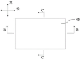
Fig. 5 is a schematic structural view of a bottom protection plate 40 according to an embodiment of the present disclosure. Fig. 6 is an exploded view of the bottom protection plate 40 according to an embodiment of the present disclosure. Fig. 7 is an enlarged schematic view of a portion a of the bottom cover 40 according to an embodiment of the present disclosure. As shown in fig. 2, 5, 6 and 7, in some embodiments of the present application, a bottom cover 40 is used to form a case 30 of the battery 10, the bottom cover 40 includes a buffer layer 41, and the buffer layer 41 is provided with a plurality of openings 411 extending along a first direction, wherein the first direction intersects with the vertical direction.
Specifically, the buffer layer 41 refers to a layered structure having a certain deformation capability, and absorbing external impact by its own deformation, thereby achieving a buffering effect.
The opening 411 is a hole structure provided on the surface of the buffer layer 41 and extending a certain length toward the inside of the buffer layer 41, for communicating the inside and the outside of the buffer layer 41, so that when the buffer layer 41 is deformed by compression, the opening 411 is deformed by compression to absorb the impact, and the gas compressed in the opening 411 is discharged to the outside of the buffer layer 41. The specific cross-sectional shape of the opening 411 is not limited, and may be a circular hole, a square hole, or a hole structure with other shapes.
The intersection of first direction and vertical direction means that the first direction can not set up along vertical direction, and trompil 411 can not set up along vertical direction promptly to guarantee that the impact along vertical direction has the contained angle with the radial direction of trompil 411, the impact can act on trompil 411 along radial direction, thereby makes trompil 411 take place to warp along radial direction, utilizes the space in the trompil 411 to cushion the impact effectively.
According to the backplate 40 at the bottom of this application, through setting up buffer layer 41, can reduce the deformation that external impact caused backplate 40 at the bottom effectively, thereby reduce or avoid causing the damage of the cooling plate in box 30 or the deformation of electric core 21, simultaneously, further set up the trompil 411 that extends along the first direction in buffer layer 41, and the extending direction of trompil 411 is crossing with the first direction, when backplate 40 receives the impact at the bottom, can further reduce the deformation that the impact caused backplate 40 at the bottom through the radial compression deformation of trompil 411, thereby reduce or avoid causing the damage of the cooling plate in box 30 or the deformation of electric core 21, guarantee security and the reliability that battery 10 used, guarantee driving safety.
In some embodiments of the present invention, as shown in fig. 2, 5, 6 and 7, the first direction is a horizontal direction.
Specifically, the opening 411 may be provided along the length direction of the floor panel 40, or along the width direction of the floor panel 40, or along an arbitrary angle direction within the horizontal direction. The length direction and the width direction of the bottom guard plate 40 are both in the horizontal direction, and the thickness direction of the bottom guard plate 40 is in the vertical direction and is perpendicular to the radial direction of the opening 411.
The openings 411 are arranged in the horizontal direction, so that when the bottom protection plate 40 is impacted in the vertical direction, the openings 411 can be maximally extruded and deformed in the radial direction, and the impact absorption capacity of the buffer layer 41 is improved.
Fig. 8 is a schematic sectional view B-B of the bottom protection plate 40 according to an embodiment of the present disclosure. Fig. 9 is a schematic view of a cross-sectional view of a bottom protective plate 40 according to an embodiment of the present disclosure. As shown in fig. 5 to 9, in some embodiments of the present invention, the bottom protective plate 40 further includes a first surface layer 42 and a second surface layer 43, and the first surface layer 42, the buffer layer 41 and the second surface layer 43 are sequentially disposed along a vertical direction.
Specifically, the first surface layer 42 and the second surface layer 43 are respectively disposed on both sides of the cushion layer 41 in the vertical direction, thereby forming the outer surface of the bottom protective plate 40 for supporting and protecting the cushion layer 41 in the middle, preventing the cushion layer 41 from contacting or rubbing against other components, and preventing the cushion layer 41 from being damaged.
As shown in fig. 2 and 5 to 9, in some embodiments of the present invention, the first surface layer 42 is an insulating material layer and is disposed toward the battery cells 21 in the box 30.
Specifically, the first surface layer 42 is configured to be disposed toward the battery cell 21 in the box 30, that is, the first surface layer 42, the buffer layer 41, and the second surface layer 43 are sequentially disposed from top to bottom along the vertical direction, so that the first surface layer 42 is disposed close to the battery cell 21, and the second surface layer 43 is disposed far from the battery cell 21. Since the battery cell 21 may discharge during operation, in order to prevent the occurrence of electric conduction between the battery cell 21 and the first surface layer 42, the first surface layer 42 is disposed as an insulating material layer and is disposed toward the battery cell 21 in the case 30.
The first surface layer 42 may be a layered structure made of a non-metal material, and may specifically be an insulating material such as a composite material, plastic, or ceramic.
Referring again to fig. 2 and 5-9, in some embodiments of the present invention, second surface layer 43 is a rigid material layer and is disposed toward the exterior of box 30.
Specifically, the second surface layer 43 is configured to be disposed toward the outside of the box body 30, that is, the first surface layer 42, the buffer layer 41, and the second surface layer 43 are sequentially disposed from top to bottom along the vertical direction, and the first surface layer 42 is disposed close to the battery cell 21, and the second surface layer 43 is disposed away from the battery cell 21. Since the second surface layer 43 is disposed toward the outside of the box body 30, and the second surface layer 43 is disposed as a rigid material layer, the second surface layer 43 first receives external impact and can absorb most of the impact energy, and then the remaining energy is dispersed and buffered by the buffer layer 41, or even absorbed completely, so as to reduce or avoid damage to the cooling plate in the box body 30 or deformation of the battery cell 21.
The second surface layer 43 may be made of steel plate or aluminum plate, or other plate-like structures with impact resistance.
As shown in fig. 2 and 5 to 9, in some embodiments of the present invention, the ratio of the thicknesses of the first surface layer 42, the buffer layer 41, and the second surface layer 43 in the vertical direction is in the range of 1:1:1 to 1:8:4, in the above range.
Specifically, the minimum thickness ratio of the first superficial layer 42 to the buffer layer 41 and the minimum thickness ratio of the second superficial layer 43 is 1:1:1, the ratio of the maximum thickness of the first superficial layer 42 to the buffer layer 41 to the maximum thickness of the second superficial layer 43 is 1:8:4. within this range, the impact resistance of the second surface layer 43 and the impact absorption of the cushion layer 41 can be effectively ensured.
Referring to fig. 5 to 9, in some embodiments of the present invention, the buffer layer 41 is an elastic material layer.
The elastic material layer has good deformability, so that the impact received by the bottom protection plate 40 is absorbed, and meanwhile, the elastic material layer has good deformation recovery capability and can recover to the original state after losing the impact effect, so that the elastic material layer is used for absorbing the impact received by the bottom protection plate 40 again.
Referring to fig. 2 and 5 to 9, in some embodiments of the present invention, the elastic material layer is at least one of a silicone rubber layer or a polyurethane layer, and two side surfaces of the elastic material layer along the vertical direction are respectively bonded to the first surface layer 42 and the second surface layer 43.
Specifically, the elastic material layer may be a silicone rubber layer, or the elastic material layer may be a polyurethane layer, or the elastic material layer may be a composite layer composed of a silicone rubber layer and a polyurethane layer. Since the silicone rubber or polyurethane has its own viscosity, before the rubber or polyurethane is not formed into a laminated structure, the silicone rubber or polyurethane may be directly adhered to one of the first surface layer 42 and the second surface layer 43, and then the other of the first surface layer 42 and the second surface layer 43 may be adhered to the other side of the elastic material layer, the silicone rubber or polyurethane may be formed into the cushion layer 41 by pressing the first surface layer 42 and the second surface layer 43, and then the cushion layer 41 after molding may be perforated, or a tubular structure may be embedded into the cushion layer 41 before molding, and after the cushion layer 41 is molded, the tubular structure may be drawn out, so as to form the opening 411, and finally the floor sheathing panel 40 may be formed.
Referring to fig. 2 and 5 to 9, in some embodiments of the present invention, the elastic material layer is a rubber layer, one side of the rubber layer in the vertical direction is bonded to the first surface layer 42 through a first bonding layer, and the other side of the rubber layer in the vertical direction is bonded to the second surface layer 43 through a second bonding layer.
Specifically, the rubber layer has sufficient deformation ability and ability to recover deformation, and may be provided with the opening 411 before being bonded to the first surface layer 42 and the second surface layer 43. The elastic material layer is provided as a rubber layer, and the top surface of the rubber layer in the vertical direction is bonded to the first surface layer 42 through a first adhesive layer, and the bottom surface of the rubber layer in the vertical direction is bonded to the second surface layer 43 through a second adhesive layer, thereby obtaining the floor sheathing 40.
Referring to fig. 2 and 5 to 9, in some embodiments of the present invention, the thermal conductivity of the first adhesive layer is greater than or equal to the thermal conductivity of the second adhesive layer.
Specifically, the thermal conductivity represents the thermal conductivity of a material, and means the heat passing through a certain thickness and a certain area within a certain time and a certain temperature difference.
Because first tie coat is used for connecting first surface layer 42 and buffer layer 41, and first surface layer 42 sets up towards electric core 21 in the box 30, and the battery can produce a large amount of heats in the during operation, in order to dispel the heat to the inside of box 30, sets up the coefficient of heat conductivity that the coefficient of heat conductivity is greater than or equal to the second tie coat of first tie coat to the heat of the inside of box 30 of being convenient for dispels the heat through first surface layer 42 and first tie coat. Meanwhile, the heat conductivity coefficient of the second bonding layer is smaller than or equal to that of the first bonding layer, so that external high temperature can be prevented from being conducted to the inside of the box body 30 through the second bonding layer, and normal work of the battery cell 21 in the box body 30 is guaranteed.
Referring to fig. 5 to 9, in some embodiments of the present invention, the opening 411 is a through hole penetrating the buffer layer 41; and/or, opening 411 is a blind via extending into buffer layer 41.
Specifically, the opening 411 may be provided as a through hole and/or a blind hole, both of which are capable of being effectively compressively deformed in the radial direction, thereby reducing deformation of the backplate 40 caused by external impact.
Referring again to fig. 5-9, in some embodiments of the present invention, the porosity of the plurality of openings 411 on the buffer layer 41 ranges from greater than 0 to less than 40%.
Specifically, the porosity is a percentage of a pore volume in the bulk material to a total volume of the material in a natural state, that is, a volume ratio of the open hole 411 when the backplate 40 is not subjected to an impact and is not deformed in the radial direction.
When the porosity of the plurality of openings 411 on the buffer layer 41 has a range value of 0, the buffer layer 41 can reduce the impact only by the deformation of its material, and the inside thereof has no further compression space, thereby affecting the buffering effect of the buffer layer 41, and therefore, the porosity is set to be greater than 0. When the range of the porosity of the plurality of openings 411 on the buffer layer 41 is greater than 40%, the restorability of the buffer layer 41 is reduced due to an excessively high porosity, so that the buffer layer 41 cannot be restored to its original shape, and the subsequent buffering effect of the buffer layer 41 is affected.
Setting the porosity to be more than 0 and less than 40% ensures sufficient compression space within the buffer layer 41, so that the contractible deformation and recoverable characteristics of the buffer layer 41 can be effectively exerted.
Referring to fig. 2 and 5 to 9, a second aspect of the present invention provides a case 30 for constituting a battery, the case 30 having a bottom cover 40 of any one of the above.
Since the box body 30 in the present application has the bottom protection plate 40 in any of the above embodiments, and has the same technical features as the bottom protection plate 40, the same technical effects can be achieved, and details are not repeated herein.
Referring again to fig. 2 and 5-9, in some embodiments of the present invention, the bottom guard plate 40 is disposed outside the box 30, and the first surface layer 42 of the bottom guard plate 40 is connected to the bottom plate 321 of the box 30.
Specifically, the case 30 may include a first portion 31 and a second portion 32, wherein the first portion 31 is disposed above the second portion 32 in a vertical direction, and wherein the second portion 32 includes a bottom plate 321 and side plates 322. The bottom cover 40 is attached to the bottom of the bottom plate 321 outside the box body 30 by bonding, welding, or the like.
Connecting first surface layer 42 with bottom plate 321 of box 30 to locate bottom protection plate 40 outside box 30, can cross through bottom protection plate 40 and cushion bottom plate 321 effectively, guarantee that the trompil 411 on bottom protection plate 40 locates the outside of box 30 simultaneously, thereby can extrude the gas in the trompil 411 to the outside of box 30 when trompil 411 warp, be convenient for the compression deformation of trompil 411.
By arranging the bottom protection plate 40 outside the box body 30 and connecting the bottom protection plate 40 with the bottom surface of the bottom plate 321, the application range of the bottom protection plate 40 can be increased, the difficulty in production of the box body 30 can be reduced, and the bottom protection plate 40 only needs to be connected with the bottom surface of the bottom plate 321 in a later period.
Referring to fig. 2 and 5 to 9, in some embodiments of the present invention, the bottom protection plate 40 is a bottom plate 321 of the box body 30, the first surface layer 42 of the bottom protection plate 40 is connected to a side plate 322 of the box body 30, and the opening 411 is communicated with the outside of the box body 30.
Specifically, the box body 30 may include a first portion 31 and a second portion 32, wherein the first portion 31 is disposed above the second portion 32 in a vertical direction, the second portion 32 includes a bottom plate 321 and a side plate 322, the bottom plate 321 is the bottom guard 40 in this application, and the first surface layer 42 of the bottom guard 40 is connected to the side plate 322 of the box body 30.
The bottom guard plate 40 is used as the bottom plate 321 of the box body 30, and the first surface layer 42 of the bottom guard plate 40 is connected with the side plate 322 of the box body 30, that is, the buffer layer 41 and the second surface layer 43 are arranged outside the box body 30, so that the opening 411 is communicated with the outside of the box body 30, and therefore when the opening 411 is deformed, the gas in the opening 411 can be extruded to the outside of the box body 30, and the compression deformation of the opening 411 is facilitated.
Referring to fig. 1 to 9, a third aspect of the present invention provides a battery 10, where the battery 10 has a case 30 of any one of the above.
With reference to fig. 1 to 9, a fourth aspect of the present invention provides an electric device, which has the battery 10, and the electric device may be any one of the electric devices described above.
The foregoing description is only an overview of the technical solutions of the present application, and the present application can be implemented according to the content of the description in order to make the technical means of the present application more clearly understood, and the following detailed description of the present application is given in order to make the above and other objects, features, and advantages of the present application more clearly understandable.
As shown in fig. 2 and 5 to 9, in some embodiments of the present invention, the bottom protection plate 40 is used to form the box 30 of the battery 10, and includes a first surface layer 42, a buffer layer 41, and a second surface layer 43, the first surface layer 42, the buffer layer 41, and the second surface layer 43 are sequentially attached to each other along a vertical direction, and the buffer layer 41 is provided with a plurality of openings 411 extending along a horizontal direction. The first surface layer 42 is an insulating material layer, and is provided toward the battery cells 21 inside the case 30. The second surface layer 43 is a rigid material layer and is provided to face the outside of the case 30. The ratio range of the thicknesses of the first surface layer 42, the buffer layer 41, and the second surface layer 43 in the vertical direction is 1:1:1~1:8:4. the buffer layer 41 is an elastic material layer. The elastic material layer is a silicone rubber layer, and the top surface and the bottom surface of the elastic material layer in the vertical direction are respectively bonded with the first surface layer 42 and the second surface layer 43. The openings 411 are through holes penetrating the buffer layer 41, and the range of the porosity of the openings 411 on the buffer layer 41 is greater than 0 and less than 40%.
Finally, it should be noted that: the above embodiments are only used for illustrating the technical solutions of the present application, and are not limited thereto; although the present application has been described in detail with reference to the foregoing embodiments, it should be understood by those skilled in the art that: the technical solutions described in the foregoing embodiments may be modified, or some or all of the technical features may be equivalently replaced; these modifications and substitutions do not cause the corresponding technical solutions to depart from the scope of the technical solutions of the embodiments of the present application, and are intended to be covered by the claims and the specification of the present application. In particular, the features mentioned in the embodiments can be combined in any manner as long as there is no structural conflict. This application is not intended to be limited to the particular embodiments disclosed herein but is to cover all embodiments that may fall within the scope of the appended claims.
Claims (17)
1. The utility model provides a backplate for constitute the box of battery, its characterized in that includes:
the buffer layer, the buffer layer is equipped with a plurality of trompils that extend along first direction, wherein, first direction is crossing with vertical direction.
2. The floor panel of claim 1, further comprising a first surface layer and a second surface layer, wherein the first surface layer, the buffer layer, and the second surface layer are sequentially attached to each other in a vertical direction.
3. The floor covering of claim 2, wherein said first surface layer is a layer of insulating material and is configured to be disposed toward the cells within the enclosure.
4. A backplate in accordance with claim 3 in which the second surface layer is a layer of rigid material and is adapted to be located towards the exterior of the tank.
5. The floorboard of claim 4, wherein a ratio of thicknesses of the first surface layer, the buffer layer, and the second surface layer in a vertical direction is in a range of 1:1:1 to 1:8:4, in the above range.
6. The floorguard of any one of claims 1 to 5, wherein the first direction is a horizontal direction.
7. Backplate according to any of claims 3 to 5, in which the cushioning layer is a layer of elastomeric material.
8. The floor sheathing according to claim 7, wherein the elastic material layer is at least one of a silicone rubber layer or a polyurethane layer, and both side surfaces of the elastic material layer in the vertical direction are bonded to the first surface layer and the second surface layer, respectively.
9. The floor sheathing according to claim 7, wherein the elastic material layer is a rubber layer, one side surface of the rubber layer in the vertical direction is bonded to the first surface layer by a first bonding layer, and the other side surface of the rubber layer in the vertical direction is bonded to the second surface layer by a second bonding layer.
10. The floor sheathing according to claim 9, wherein the first adhesive layer has a thermal conductivity greater than or equal to the thermal conductivity of the second adhesive layer.
11. The floor sheathing according to any one of claims 1 to 5, wherein the opening is a through hole penetrating the cushioning layer; or, the opening is a blind hole extending to the interior of the buffer layer.
12. The floor sheathing according to any one of claims 1 to 5, wherein a porosity of the plurality of openings on the buffer layer ranges from a value greater than 0 to less than 40%.
13. A case for constituting a battery, characterized in that it has a floor panel according to any one of claims 1 to 12.
14. The cabinet as claimed in claim 13, wherein the bottom cover is provided on an outside of the cabinet, and the first surface layer of the bottom cover is connected to a bottom plate of the cabinet.
15. The cabinet as claimed in claim 13, wherein the bottom panel is a bottom panel of the cabinet, the first surface layer of the bottom panel is connected to a side panel of the cabinet, and the opening communicates with an outside of the cabinet.
16. A battery having a case according to any one of claims 13 to 15.
17. An electrical device, characterized by a battery according to claim 16.
Priority Applications (1)
| Application Number | Priority Date | Filing Date | Title |
|---|---|---|---|
| CN202222640319.3U CN218274854U (en) | 2022-10-09 | 2022-10-09 | Bottom protection plate, box body, battery and electric equipment |
Applications Claiming Priority (1)
| Application Number | Priority Date | Filing Date | Title |
|---|---|---|---|
| CN202222640319.3U CN218274854U (en) | 2022-10-09 | 2022-10-09 | Bottom protection plate, box body, battery and electric equipment |
Publications (1)
| Publication Number | Publication Date |
|---|---|
| CN218274854U true CN218274854U (en) | 2023-01-10 |
Family
ID=84750586
Family Applications (1)
| Application Number | Title | Priority Date | Filing Date |
|---|---|---|---|
| CN202222640319.3U Active CN218274854U (en) | 2022-10-09 | 2022-10-09 | Bottom protection plate, box body, battery and electric equipment |
Country Status (1)
| Country | Link |
|---|---|
| CN (1) | CN218274854U (en) |
-
2022
- 2022-10-09 CN CN202222640319.3U patent/CN218274854U/en active Active
Similar Documents
| Publication | Publication Date | Title |
|---|---|---|
| CN113906615B (en) | Power supply device, electric vehicle provided with same, and power storage device | |
| CN218414916U (en) | Separator, battery, and power consumption device | |
| CN217562780U (en) | Top cap subassembly, battery monomer, battery and consumer | |
| CN216120659U (en) | Current collector, electrode plate, electrode assembly, single battery, battery and electric device | |
| KR101381098B1 (en) | A battery which is improved damageability and repairability about low-speed impact for the electric vehicle | |
| CN216354448U (en) | Insulating part, electric core, battery and power consumption device | |
| CN219696617U (en) | Battery and electricity utilization device | |
| CN218274854U (en) | Bottom protection plate, box body, battery and electric equipment | |
| CN219180683U (en) | Battery and electricity utilization device | |
| CN115842205B (en) | Buffer assembly, battery monomer, battery and power utilization device | |
| CN115084771B (en) | High-performance battery box protection structure and automobile | |
| CN216850059U (en) | Temperature adjusting assembly, single battery, battery and power utilization device | |
| CN115084782A (en) | Electrode assembly, battery cell, battery and power consumption device | |
| CN115968515A (en) | Battery, electric equipment, method and equipment for preparing battery | |
| CN217788569U (en) | Battery cell, battery and power consumption device | |
| CN217589219U (en) | Battery and power consumption device | |
| CN220138398U (en) | Power battery pack and vehicle | |
| CN218274970U (en) | Electricity core subassembly, battery and power consumption device | |
| CN218769817U (en) | Battery monomer, battery and consumer | |
| CN115799656B (en) | Electrode assembly, battery cell, battery, device and manufacturing method related to electrode assembly | |
| CN220692169U (en) | Battery and electric equipment | |
| CN220753604U (en) | Battery and electric equipment | |
| WO2024077622A1 (en) | Battery and electric device | |
| CN220895667U (en) | Battery and electric equipment | |
| CN220692170U (en) | Battery and electric equipment |
Legal Events
| Date | Code | Title | Description |
|---|---|---|---|
| GR01 | Patent grant | ||
| GR01 | Patent grant |