CN218262955U - Weft clamping device for loom - Google Patents
Weft clamping device for loom Download PDFInfo
- Publication number
- CN218262955U CN218262955U CN202222333927.XU CN202222333927U CN218262955U CN 218262955 U CN218262955 U CN 218262955U CN 202222333927 U CN202222333927 U CN 202222333927U CN 218262955 U CN218262955 U CN 218262955U
- Authority
- CN
- China
- Prior art keywords
- weft
- elastic pressing
- pressing strip
- fixing plate
- weaving machine
- Prior art date
- Legal status (The legal status is an assumption and is not a legal conclusion. Google has not performed a legal analysis and makes no representation as to the accuracy of the status listed.)
- Active
Links
Images


Landscapes
- Looms (AREA)
Abstract
The utility model provides a weft clamping device used on a weaving machine, which is arranged on a breast beam of the weaving machine and comprises an upper clamping component and a lower clamping component positioned below the upper clamping component; the upper clamping assembly comprises an elastic pressing strip; the lower clamping assembly comprises a fixing plate; the elastic pressing strip is close to the upper surface of the fixing plate. The utility model discloses a set up elastic pressing strip and fixed plate, in the course of weaving, the wefting insertion sword drives the woof and passes the shed that upper warp and lower floor's warp formed, the reed promotes the woof and removes the contact jaw to elastic pressing strip and fixed plate, the woof gets into the tip of elastic pressing strip and fixed plate contact earlier, rethread thrust force moves to the gap between elastic pressing strip and the fixed plate, it is in by the interlock state to ensure woof after the weft insertion, and after next weft insertion, can release the gap between elastic pressing strip and the fixed plate with the woof of last introduction, prevent that the phenomenon is piled up in the lockstitching a border region to the weft shrinkage phenomenon or woof emergence.
Description
Technical Field
The utility model relates to a weaving equipment technical field especially relates to a weft clamping device for on loom.
Background
Besides the characteristics of high speed, high automation degree and high production efficiency, the rapier loom has strong variety adaptability in an active weft insertion mode, can adapt to weft insertion of various yarns, and is the most widely applied shuttleless loom at present. Meanwhile, the rapier loom has obvious advantages in the aspect of multi-color weft weaving, and can produce yarn dyed products with 16-color weft yarns.
The edges of the cloth woven by the rapier loom are rough edges, and the cloth is required to be subjected to a seaming process before being sold. If weft yarns are piled up in the serging area in the cloth production process, the serging operation is affected, and particularly, the weft yarns are easy to pile up in the cloth production process due to the ultrahigh weft density of the high-thickness special fiber fabric. In addition, if the weft shrinkage phenomenon occurs in the cloth production process, the quality of the cloth is seriously influenced. Therefore, in the cloth production process, the end parts of the weft yarns need to be finished after weft insertion is finished so as to prevent weft yarns from being accumulated in a serging area or weft shrinkage caused by uneven stress in the cloth production process.
The existing common method is that a drafting nozzle is arranged at the position where the weft insertion of the weaving machine is finished, the drafting nozzle provides an air source by an independent air bag, and a drafting force is applied to flying weft yarn by using larger air pressure to ensure that the weft yarn can be straightened smoothly and prevent the weft shrinkage. In order to overcome the drawback of above-mentioned method, the patent of application number CN202123000459.6 discloses a terminal clamping device of loom weft, including power unit and fixture, fixture locates on same vertical plane with power unit, power unit includes a drive shaft and a mounting plate, be equipped with a cam disc in the drive shaft, it is equipped with two first mounting brackets, two sets of to control side by side on the first mounting plate erect a first pivot between the first mounting bracket, both ends are rotated and are connected on two first mounting brackets, two about the first pivot between the first mounting bracket are equipped with a initiative swing arm and a driven swing arm. The device utilizes a driving shaft to be connected with a weaving machine to rotate, drives a cam disc to drive a driving swing arm, and then drives a connecting rod group to push a swing plate to swing, so that weft threads are clamped. The device has a complex structure and is difficult to be connected with a weaving machine; at the same time, the device completely depends on the power source provided by the weaving machine.
In view of the above, there is a need for an improved weft yarn gripping device for a loom that solves the above problems.
SUMMERY OF THE UTILITY MODEL
An object of the utility model is to provide a weft clamping device for on loom, through setting up elastic pressing strip and fixed plate, in the textile process, the wefting sword drives the woof and passes the shed that upper warp and lower floor's warp formed, when the woof passes the shed, the reed promotes the woof and removes the contact jaw to elastic pressing strip and fixed plate, the woof gets into the tip of elastic pressing strip and fixed plate contact earlier, rethread thrust force removes to the gap between elastic pressing strip and the fixed plate, it is in by the interlock state to ensure to insert the woof after the weft, and after next weft insertion, can release the gap between elastic pressing strip and the fixed plate with the woof of last introduction, prevent that the phenomenon is piled up in the lockage region to the weft shrinkage or woof emergence of phenomenon.
In order to achieve the purpose, the utility model provides a weft yarn clamping device used on a weaving machine, which is arranged on a breast beam of the weaving machine and comprises an upper clamping component and a lower clamping component positioned below the upper clamping component; the upper clamping assembly comprises an elastic pressing strip; the lower clamping assembly comprises a fixing plate; the elastic pressing strip is close to the upper surface of the fixing plate; in the weaving process, the weft feeding sword drives weft yarns to penetrate through a shed formed by upper-layer warp yarns and lower-layer warp yarns, and when the weft yarns penetrate through the shed, the reed sends the weft yarns into gaps between the elastic pressing strips and the fixing plate from contact ends of the elastic pressing strips and the fixing plate so as to clamp the weft yarns.
As a further improvement of the utility model, the upper surface of the fixing plate is provided with a groove, and the elastic pressing strip is positioned in the groove; the elastic pressing strips and two ends of the groove in contact with each other are tilted, a certain angle is formed between each elastic pressing strip and the corresponding groove, and accordingly the weft yarns can enter the space between the spring steel wire and the fixing plate conveniently.
As a further improvement of the utility model, the elastic pressing strip is a spring steel wire, and the spring steel wire is positioned in the groove; the diameter of the spring steel wire is 1-3mm.
As a further improvement of the utility model, the fixing plate is 100-120mm long, 8-10mm wide and 1-3mm thick.
As a further improvement of the utility model, the upper clamping component further comprises an upper fixing block, and the elastic pressing strip is fixed on the side wall of the upper fixing block; the lower clamping assembly further comprises a lower fixing block, and the fixing plate is fixed on the side wall of the lower fixing block; the elastic pressing strip and the fixing plate are located on the same side.
As a further improvement of the present invention, a weft holding device for use in a loom further comprises a base of an L-shape, wherein a vertical surface of the base L-shape is used for fixing the upper holding assembly and the lower holding assembly, and a horizontal plane is used for fixing the upper holding assembly and the lower holding assembly on a breast beam of the loom.
As a further improvement of the utility model, the upper fixed block and the lower fixed block have the same size, the length is 20-40mm, the width is 10-30mm, and the thickness is 6-10mm.
As a further improvement of the utility model, the weft yarn clamping device used on the weaving machine further comprises an auxiliary mechanism used for controlling the up-and-down movement of the elastic pressing strip; when the reed drives the weft yarn to move to the weft yarn clamping device on the weaving machine, the auxiliary mechanism drives the elastic pressing strip to lift upwards and then presses downwards to clamp the weft yarn between the elastic pressing strip and the fixing plate.
As a further improvement of the present invention, the auxiliary mechanism includes one of a cylinder, a motor, or a connecting rod.
As a further improvement of the utility model, a screw hole is arranged on the base, and the screw passes through the screw hole is fixed on the breast beam of the loom.
The utility model has the advantages that:
(1) The utility model provides a pair of weft clamping device for on loom, through setting up elastic pressing strip and fixed plate, and press close to the upper surface of fixed plate with the elastic pressing strip, in the weaving process, the wefting sword drives the woof and passes the shed that upper warp and lower floor's warp formed, when the woof passes the shed, the reed promotes the woof and removes the contact jaw to elastic pressing strip and fixed plate, the woof gets into the tip of elastic pressing strip and fixed plate contact earlier, rethread thrust is removed to the gap between elastic pressing strip and the fixed plate, by the centre gripping between elastic pressing strip and fixed plate. Firstly, after each weft insertion, the weft yarn is clamped by the elastic pressing strip and the fixing plate, so that the weft yarn is in an occluded state after the weft insertion, the weft yarn of the last weft insertion is prevented from being drawn back due to the fact that a single side has no tension or no clamping in the next weft insertion process, and the weft shrinkage phenomenon is prevented; secondly, after the next weft insertion, the weft inserted at the last time can push the weft inserted at the last time out of a gap between the elastic pressing strip and the fixing plate (namely, different wefts cannot be wound), so that the weft is prevented from being accumulated in a serging area, and the method is particularly suitable for weaving high-thickness multilayer special fiber cloth.
In addition, a groove is formed in the upper surface of the fixing plate, and two ends, contacting with the groove, of the spring steel wire are tilted, so that weft yarns can conveniently enter between the spring steel wire and the fixing plate; meanwhile, when the weft yarn is clamped between the elastic pressing strip and the fixing plate, the friction force between the weft yarn and the elastic pressing strip and between the weft yarn and the fixing plate can be increased, the weft yarn can be more favorably clamped, and the weft yarn clamp is particularly suitable for weft yarns with smooth surfaces, high strength (difficult to be clamped off) and high hardness.
(2) The utility model provides a pair of a weft clamping device for on loom, device simple structure, the installation is simple, and application scope is wide.
Drawings
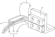
Fig. 1 is a schematic perspective view of a weft holding device used in a loom according to the present invention.
Fig. 2 is a schematic perspective view of the upper clamping assembly shown in fig. 1.
Fig. 3 is a schematic perspective view of the lower clamping assembly shown in fig. 1.
Fig. 4 is a schematic perspective view of the base in fig. 1.
Fig. 5 is a schematic view of the working principle of the weft holding device used in the loom of the present invention.
Fig. 6 is a process flow chart of weaving by using the weft holding device of the utility model.
Reference numerals
1-an upper clamping assembly; 2-a lower clamping assembly; 3-the weft yarn; 4-upper warp yarns; 5-lower layer warp yarns; 6-a base; 11-spring steel wire; 12-fixing the block; 21-fixing the plate; 22-a groove; and 23-lower fixing block.
Detailed Description
In order to make the objects, technical solutions and advantages of the present invention clearer, the present invention will be described in detail with reference to the accompanying drawings and specific embodiments.
It should be noted that, in order to avoid obscuring the present invention with unnecessary details, only the structures and/or processing steps closely related to the aspects of the present invention are shown in the drawings, and other details not relevant to the present invention are omitted.
In addition, it is also to be noted that the terms "comprises," "comprising," or any other variation thereof, are intended to cover a non-exclusive inclusion, such that a process, method, article, or apparatus that comprises a list of elements does not include only those elements but may include other elements not expressly listed or inherent to such process, method, article, or apparatus.
Referring to fig. 1 to 6, the present invention provides a weft yarn clamping device for a loom, which comprises an upper clamping assembly 1 and a lower clamping assembly 2 located below the upper clamping assembly 1. The upper clamping assembly 1 comprises an elastic pressing strip; the lower clamping assembly 2 comprises a fixing plate 21; the elastic pressing strip is close to the upper surface of the fixing plate 21. With such an arrangement, as shown in fig. 5 and 6, during the weaving process, the weft feeder rapier drives the weft yarn 3 to pass through the shed formed by the upper layer warp yarn 4 and the lower layer warp yarn 5 (i.e. the motion direction of the weft feeder rapier is from the left side to the right side of the fabric in fig. 5), when the weft yarn 3 passes through the shed, the reed feeds the weft yarn 3 into the gap formed by the elastic pressing strip and the fixing plate 21 from the contact end of the elastic pressing strip and the fixing plate 21, so as to realize the clamping of the weft yarn 3, specifically: the reed pushes the weft yarns 3 to move to a contact end of the elastic pressing strip and the fixing plate 21 (at the moment, the reed returns, the movement direction of the reed is from the front side to the rear side of the fabric in the graph 5, namely the movement direction of the reed is vertical to the movement direction of the weft feeding sword), the weft yarns 3 firstly enter the contact end of the elastic pressing strip and the fixing plate 21 and then move to a gap between the elastic pressing strip and the fixing plate 21 through a punching force (the weft yarns 3 have certain hardness, the weft yarns 3 with high impact force can push the elastic pressing strip away and then are clamped between the elastic pressing strip and the fixing plate 21); after each weft insertion, the weft yarns 3 are clamped by the elastic pressing strips and the fixing plate 21, so that the weft yarns 3 of the last weft insertion are prevented from being drawn back due to the fact that a single side has no tension or no clamping in the next weft insertion process, and the weft shrinkage phenomenon is prevented; meanwhile, after the next weft insertion, the weft 3 inserted last time pushes the weft 3 inserted last time out of the gap between the elastic pressing strip and the fixing plate 21 (i.e. winding between different weft 3 does not occur), so that the weft 3 is prevented from being stacked in the serging area.
Specifically, as shown in fig. 1 and fig. 2 (the elastic pressing strips are located on the same vertical plane), the upper clamping assembly 1 further includes an upper fixing block 12, the elastic pressing strips are fixed on the side walls of the upper fixing block 12, and preferably, the elastic pressing strips are welded on the side walls of the upper fixing block 12. In some embodiments, the elastic bead is a spring steel wire 11, the diameter of the spring steel wire 11 is 1-3mm, and the spring steel wire 11 is preferably a carbon steel spring steel wire with a diameter of 2mm.
As shown in fig. 1 and 3, the lower clamping assembly 2 further includes a lower fixing block 23, and the fixing plate 21 is fixed to a side wall of the lower fixing block 23, and preferably, the fixing plate 21 is welded to the side wall of the lower fixing block 23. The spring wire 11 and the fixing plate 21 are located on the same side. The upper surface of the fixing plate 21 is provided with a groove 22, the spring steel wire 11 is positioned in the groove 22, and both ends of the spring steel wire 11 contacting with the groove 22 are tilted so as to form a certain angle with the groove 22. According to the arrangement, firstly, in the weaving process, the weft feeding sword drives the weft yarns 3 to penetrate through a shed formed by upper-layer warp yarns 4 and lower-layer warp yarns 5, when the weft yarns 3 penetrate through the shed, the reed pushes the weft yarns 3 to move to the contact end of the spring steel wire 11 and the fixed plate, the weft yarns 3 firstly enter the angle formed by the spring steel wire 11 and the fixed plate 21 (namely, the position A in the figure 1), then the weft yarns 3 move to the gap formed by the spring steel wire 11 and the fixed plate 21, and finally the weft yarns are clamped in the gap between the spring steel wire 11 and the fixed plate 21, namely, two ends of the spring steel wire 11, which are in contact with the grooves 22, are tilted, so that the weft yarns can conveniently enter between the spring steel wire 11 and the fixed plate 21. Secondly, when the weft yarn 3 is clamped between the spring steel wire 11 and the fixing plate 21, the design of the groove 22 can increase the friction force between the weft yarn 3 and the spring steel wire 11 and the fixing plate 21, which is more beneficial to clamping the weft yarn 3, and is particularly suitable for weft yarns 3 with smooth surface, high strength (not easy to be clamped off) and high hardness, such as yarns composed of glass fibers, carbon fibers and the like.
Specifically, the fixing plate 21 has a length of 100-120mm, a width of 8-10mm, and a thickness of 1-3mm, preferably a length of 110mm, a width of 9mm, and a thickness of 2mm. The upper fixing block 12 and the lower fixing block 23 have the same size, the length is 20-40mm, the width is 10-30mm, and the thickness is 6-10mm. Preferably 30mm long, 20mm wide and 8mm thick.
In some embodiments, the weft gripping device for weaving machines also comprises a base 6 (not shown in fig. 5) of the L-shape. With the arrangement, on one hand, the weft clamping device for the weaving machine can be fixed on a breast beam of the weaving machine through the base 6; on the other hand, the height of the weft yarn clamping device used on the weaving machine can be adjusted by changing the thickness of the base 6, and then the heights of the spring steel wire 11 and the fixing plate 21 are adjusted, so that the gap formed between the spring steel wire 11 and the fixing plate 21 and the weft yarn 3 are positioned at the same height as far as possible, and the weft yarn 3 can conveniently pass through. As shown in fig. 4, specifically, the L-shaped vertical surface and the horizontal surface of the base 6 are both provided with screw holes, and the screw holes of the vertical surface are used for being fixed with the upper fixing block 12 and the lower fixing block 23 respectively through screws (the upper fixing block 12 and the lower fixing block 23 are provided with corresponding screw holes); the screw holes on the horizontal plane are used for being fixed with the breast beam of the weaving machine through screws (when the base 6 is not arranged, the device can be arranged on the breast beam of the weaving machine through a connecting bracket, or the upper fixing block 12 and the lower fixing block 23 are directly and respectively fixed on the breast beam of the weaving machine).
In other embodiments, the weft holding device for weaving machines further comprises an auxiliary mechanism (not shown) for controlling the up-and-down movement of the spring wire 11. When the reed drives the weft yarn 3 to move to the weft yarn clamping device used on the weaving machine, the auxiliary mechanism drives the spring steel wire 11 to lift up so that the weft yarn 3 can penetrate between the spring steel wire and the spring steel wire 11, and then the auxiliary mechanism moves the spring steel wire 11 downwards so that the spring steel wire 11 is pressed down to clamp the weft yarn 3 between the spring steel wire 11 and the fixing plate 21 more firmly. The auxiliary mechanism comprises one of a cylinder, a motor or a connecting rod.
The working principle of the weft yarn clamping device used on the weaving machine is as follows: the weft thread clamping device for the weaving machine is first fixed on the breast beam of the weaving machine (at the end of the weft insertion) by means of a base 6 and the angle of the base 6 is adjusted so that the device and the weft thread 3 are as far as possible on the same horizontal plane. Then, the weaving operation is started, during the weaving process, the weft feeder drives the weft yarn 3 to pass through a shed formed by the upper layer warp yarn 4 and the lower layer warp yarn 5, when the weft yarn 3 passes through the shed, the reed pushes the weft yarn 3 to move to an angle formed by the spring steel wire 11 and the fixing plate 21 (namely, at a position A in the figure 1, the reed is retracted at the moment), the auxiliary mechanism drives the spring steel wire 11 to lift upwards firstly, when the weft yarn 3 passes between the spring steel wire 11 and the fixing plate 21, the auxiliary mechanism further moves the spring steel wire 11 downwards to press the spring steel wire 11 downwards, so that the weft yarn 3 is clamped between the spring steel wire 11 and the fixing plate 21 more firmly (when the auxiliary mechanism is not arranged, when the weft yarn 3 passes through the shed, the reed pushes the weft yarn 3 to move to a contact end of the spring steel wire 11 and the fixing plate 21, the weft yarn 3 firstly enters the angle formed by the spring steel wire 11 and the fixing plate 21 (namely, at a position A in the figure 1), and then the weft yarn 3 moves to a gap formed by the spring steel wire 11 and the fixing plate 21 finally clamped in the gap between the spring steel wire 11 and the fixing plate 21. Next weft insertion is performed, and after next weft insertion, the weft yarn 3 of the weft insertion pushes the weft yarn 3 of the previous weft insertion out of the gap between the spring steel wire 11 and the fixed plate 21.
To sum up, the utility model provides a weft clamping device for on loom, through setting up elastic pressing strip and fixed plate, and press close to the upper surface of fixed plate with the elastic pressing strip, at the textile process, the weft feeding sword drives the woof and passes the shed that upper warp and lower floor's warp formed, then the reed promotes the woof and removes the contact jaw to spring wire and fixed plate, the woof gets into the tip of elastic pressing strip and fixed plate contact earlier, rethread thrust moves to the gap between elastic pressing strip and the fixed plate in to by the centre gripping between elastic pressing strip and fixed plate. Firstly, after each weft insertion, the weft yarn is clamped by the elastic pressing strip and the fixing plate, so that the weft yarn is in an occluded state after the weft insertion, the weft yarn of the last weft insertion is prevented from being drawn back due to the fact that a single side has no tension or no clamping in the next weft insertion process, and the weft shrinkage phenomenon is prevented; secondly, after the next weft insertion, the weft inserted at the last time can push the weft inserted at the last time out of a gap between the elastic pressing strip and the fixing plate (namely, different wefts cannot be wound), so that the weft is prevented from being accumulated in a serging area, and the method is particularly suitable for weaving high-thickness multilayer special fiber cloth; the device has simple structure and wide application range.
Although the present invention has been described in detail with reference to the preferred embodiments, those skilled in the art will appreciate that various modifications and equivalent arrangements can be made without departing from the spirit and scope of the present invention.
Claims (10)
1. A weft holding device for a weaving machine, which is mounted on a breast beam of the weaving machine, characterized in that: comprises an upper clamping assembly and a lower clamping assembly positioned below the upper clamping assembly; the upper clamping assembly comprises an elastic pressing strip; the lower clamping assembly comprises a fixing plate; the elastic pressing strip is close to the upper surface of the fixing plate; in the weaving process, the weft feeding sword drives weft yarns to penetrate through a shed formed by upper-layer warp yarns and lower-layer warp yarns, and when the weft yarns penetrate through the shed, the reed sends the weft yarns into gaps between the elastic pressing strips and the fixing plate from contact ends of the elastic pressing strips and the fixing plate so as to clamp the weft yarns.
2. A weft holding device for a weaving machine according to claim 1, characterized in that: the upper surface of the fixing plate is provided with a groove, and the elastic pressing strip is positioned in the groove; the elastic pressing strip and two ends of the groove in contact are tilted, a certain angle is formed between the elastic pressing strip and the groove, and the weft yarns can enter the space between the elastic pressing strip and the fixing plate conveniently.
3. A weft holding device for a loom according to claim 2, characterized in that: the elastic pressing strip is a spring steel wire which is positioned in the groove; the diameter of the spring steel wire is 1-3mm.
4. A weft holding device for a weaving machine according to claim 1, characterized in that: the fixing plate is 100-120mm long, 8-10mm wide and 1-3mm thick.
5. A weft holding device for use in a weaving machine according to claim 1, characterized in that: the upper clamping assembly further comprises an upper fixing block, and the elastic pressing strip is fixed on the side wall of the upper fixing block; the lower clamping assembly further comprises a lower fixing block, and the fixing plate is fixed on the side wall of the lower fixing block; the elastic pressing strip and the fixing plate are located on the same side.
6. A weft holding device for use in a weaving machine according to claim 1, characterized in that: the weft clamping device for the loom further comprises an L-shaped base, wherein the vertical surface of the L-shaped base is used for fixing the upper clamping assembly and the lower clamping assembly, and the horizontal surface is used for being fixed on a breast beam of the loom.
7. A weft holding device for a weaving machine according to claim 5, characterized in that: the upper fixing block and the lower fixing block are the same in size, 20-40mm long, 10-30mm wide and 6-10mm thick.
8. A weft holding device for a weaving machine according to claim 1, characterized in that: the weft clamping device used on the weaving machine further comprises an auxiliary mechanism used for controlling the elastic pressing strip to move up and down; when the reed drives the weft yarn to move to the weft yarn clamping device on the weaving machine, the auxiliary mechanism drives the elastic pressing strip to lift upwards and then presses downwards to clamp the weft yarn between the elastic pressing strip and the fixing plate.
9. A weft holding device for a weaving machine according to claim 8, characterized in that: the auxiliary mechanism comprises one of a cylinder, a motor or a connecting rod.
10. A weft holding device for a weaving machine according to claim 6, characterized in that: the base is provided with a screw hole, and the screw fixes the base on a breast beam of the loom through the screw hole.
Priority Applications (1)
| Application Number | Priority Date | Filing Date | Title |
|---|---|---|---|
| CN202222333927.XU CN218262955U (en) | 2022-09-02 | 2022-09-02 | Weft clamping device for loom |
Applications Claiming Priority (1)
| Application Number | Priority Date | Filing Date | Title |
|---|---|---|---|
| CN202222333927.XU CN218262955U (en) | 2022-09-02 | 2022-09-02 | Weft clamping device for loom |
Publications (1)
| Publication Number | Publication Date |
|---|---|
| CN218262955U true CN218262955U (en) | 2023-01-10 |
Family
ID=84711195
Family Applications (1)
| Application Number | Title | Priority Date | Filing Date |
|---|---|---|---|
| CN202222333927.XU Active CN218262955U (en) | 2022-09-02 | 2022-09-02 | Weft clamping device for loom |
Country Status (1)
| Country | Link |
|---|---|
| CN (1) | CN218262955U (en) |
-
2022
- 2022-09-02 CN CN202222333927.XU patent/CN218262955U/en active Active
Similar Documents
| Publication | Publication Date | Title |
|---|---|---|
| US6058980A (en) | Method for cutting a selvedge of a weft insertion side of a rapier loom | |
| JP2941798B2 (en) | Controllable weft yarn gripping device and device for minimizing weft waste when weaving on looms, especially gripper looms | |
| CN218262955U (en) | Weft clamping device for loom | |
| CN210914731U (en) | Electronic precision bobbin winder | |
| CN111235724B (en) | Rapier weaving machine shuttle unilateral grabbing device | |
| CN113122999A (en) | Automatic position-finding variable-width weft insertion device and working method thereof | |
| JP4376896B2 (en) | Method for weaving fabrics with plain and twill weaves and looms for carrying out the method | |
| CN201224800Y (en) | Three-dimensional pattern weaving apparatus | |
| CN100351446C (en) | Magnetic suspension shuttle weaving with magnetic drawing apparatus | |
| CN218436098U (en) | Loom weft end clamping device | |
| CN2786165Y (en) | Inner temple for tubular woven fabric | |
| CN117248318B (en) | Weft finding mechanism of loom | |
| CN216193070U (en) | High-precision warp plain velvet weaving machine | |
| CN211665255U (en) | Yarn guide plate for air-jet loom | |
| CN216919593U (en) | Selvedge clamping mechanism of air jet loom | |
| CN214655555U (en) | Weft yarn pulling-back device of weaving machine | |
| CN220685381U (en) | Warp let-off device for circular loom | |
| CN216237508U (en) | Guide assembly based on circular weaving machine for gauze processing | |
| CN214736433U (en) | Loom warp stop frame trailing arm | |
| CN212834320U (en) | Weft releasing device for weaving glass fiber cloth | |
| CN220433232U (en) | Knitted fabric pressing device | |
| CN215328572U (en) | Warping machine for warp yarn | |
| CN210529158U (en) | Multi-shuttle plastic circular weaving machine | |
| CN212865145U (en) | Warp tension adjusting mechanism of three-dimensional weaving machine | |
| CN219385520U (en) | Cut plush equipment collection device |
Legal Events
| Date | Code | Title | Description |
|---|---|---|---|
| GR01 | Patent grant | ||
| GR01 | Patent grant |