CN218237199U - LED illuminating lamp for classroom - Google Patents
LED illuminating lamp for classroom Download PDFInfo
- Publication number
- CN218237199U CN218237199U CN202222460230.9U CN202222460230U CN218237199U CN 218237199 U CN218237199 U CN 218237199U CN 202222460230 U CN202222460230 U CN 202222460230U CN 218237199 U CN218237199 U CN 218237199U
- Authority
- CN
- China
- Prior art keywords
- lamp
- fixedly connected
- bolt
- classroom
- groove
- Prior art date
- Legal status (The legal status is an assumption and is not a legal conclusion. Google has not performed a legal analysis and makes no representation as to the accuracy of the status listed.)
- Active
Links
Images


Abstract
The utility model relates to the technical field of illuminating lamps, and discloses a LED illuminating lamp for classrooms, which comprises a lamp shell, wherein a first through groove is formed in the middle of the side surface of the lamp shell, a first bolt is fixedly connected with the inner side thread of the first through groove through the thread of a bolt rod, a second through groove is formed in the middle of the bottom end of the side surface of the lamp shell, a second bolt is fixedly connected with the inner side thread of the second through groove through the thread of the bolt rod, a third through groove is formed in the top end of the side surface of the lamp shell, and a vent pipe is fixedly connected to the inner side of the third through groove; the LED illuminating lamp for the classroom has the eye protection function, so that students and teachers can study under the illumination condition of the LED illuminating lamp for the classroom for a long time, the eye fatigue can not occur, the eyesight of eyes and the study condition can not be influenced, the problems of stroboflash and glare can be effectively avoided, the comfort level of the LED illuminating lamp for the classroom is increased, and the safety of the LED illuminating lamp for the classroom is improved.
Description
Technical Field
The utility model relates to a light technical field, more specifically relate to a LED light for classroom.
Background
The LED illuminating lamp for classrooms is a tool for illumination, the LED is made of a semiconductor light emitting diode, the working principle is that radiation recombination generates electroluminescence, and the semiconductor light emitting device is the same as a traditional light source and can ensure that the surroundings are bright under the condition that the surrounding environment is dark, so that the using personnel can observe the surroundings conveniently and avoid visual blind areas;
however, students often suffer from eye fatigue in learning under the illumination condition of the common LED illuminating lamp for a long time, thereby affecting the eyesight of eyes and the learning condition, in addition, the common LED illuminating lamp is usually illuminated by a plurality of LED lamp tubes, if the conditions such as lamp tube explosion occur, lamp tube fragments easily fall down to hurt people, and generate heat to cause fog to be attached to the lamp tubes, thereby affecting illumination and having certain electric conduction and electric shock risks.
It is therefore highly desirable to provide an LED lighting lamp for classroom use.
SUMMERY OF THE UTILITY MODEL
In order to overcome the above-mentioned defect of prior art, the utility model provides a LED light is used in classroom to solve the problem that exists among the above-mentioned background art.
The utility model provides a following technical scheme: the utility model provides a LED light for classroom, includes the lamp body, first logical groove has been seted up at the middle part of the side of lamp body, the first logical inslot side of seting up of the side of lamp body is equipped with the screw thread, the outside that first logical groove was equipped with first bolt, the shank of bolt of first bolt is equipped with the screw thread, first bolt carries out fixed connection through the screw thread of shank of bolt and the inboard screw thread that first logical groove, the second logical groove has been seted up at the side bottom middle part of lamp body, the second logical inslot side of seting up at the side bottom middle part of lamp body is equipped with the screw thread, the outside that the second logical groove is equipped with the second bolt, the shank of bolt of second bolt is equipped with the screw thread, the screw thread that the second bolt passes through the shank of bolt carries out fixed connection with the inboard screw thread that the second leads to the groove, the third logical groove has been seted up on the top of lamp body side, third logical inslot side fixedly connected with ventilation pipe.
Furthermore, a first through hole is formed in the middle of the side face of the temperature equalizing plate, threads are arranged on the inner side of the first through hole, the side face of the temperature equalizing plate is fixedly connected to the inner wall of the lamp housing through the bolt rod threads of the first bolt and the inner side threads of the first through hole, the inner wall of the temperature equalizing plate is fixedly connected with a lamp tube on two sides of the first through hole, the inner wall of the lamp tube is fixedly connected with a lamp post, one side of the lamp post is fixedly connected to the temperature equalizing plate, one side of the lamp post, far away from the temperature equalizing plate, is fixedly connected with dustproof glass, the outer side of the dustproof glass is fixedly connected with a dustproof ring, the outer side of the dustproof ring is movably connected to the inner wall of the lamp tube, one side of the dustproof glass, far away from the lamp post, is fixedly connected with a reflector, the middle of an inner cavity of the reflector, far away from the dustproof glass, is movably connected with a radiator, the inner side of the radiator is fixedly connected with a lampshade, and the surface of the lampshade on one side, close to the reflector, is movably connected with the lampshade.
Further, a second bolt is arranged in the middle of the side face of the diffusion plate, threads are arranged on the inner side of the second bolt, and the side face of the diffusion plate is fixedly connected to the inner wall of the lamp housing through the bolt rod threads of the second bolt and the inner threads of the second through hole).
Furthermore, an air outlet fan is fixedly connected to the air outlet of the ventilation pipe, blades of the air outlet fan are arranged on one side close to the third through groove, an air inlet fan is fixedly connected to the air inlet of the ventilation pipe, and blades of the air inlet fan are arranged on one side far away from the third through groove.
Furthermore, the top fixedly connected with fixed support post of lamp body, fixed support post uses the top middle part of lamp body as the axis, fixed support post's outside fixedly connected with locking cap, the inner wall fixed connection of locking cap is at fixed support post's top.
Furthermore, the bottom end of the ventilation pipe is fixedly connected with a temperature-equalizing plate, one surface of the temperature-equalizing plate, which is close to the lamp tube, is provided with a wave-shaped structure, and the bottom end of the temperature-equalizing plate is fixedly connected with a diffusion plate.
Further, the inner wall of the temperature equalizing plate is coated with an antireflection film.
The utility model discloses a technological effect and advantage:
1. the utility model discloses a be equipped with the diffuser plate, be favorable to letting the classroom have the eyeshield function with the LED light, make student and mr study under this kind of classroom is with LED light illumination condition for a long time, eye fatigue can not appear, can not influence eyes eyesight and study condition yet, avoided the problem of stroboflash and glare effectively, increased the comfort level of classroom with the LED light.
2. The utility model discloses a be equipped with the anti-reflection coating of reflector and fluorescent tube inner wall, be favorable to increasing LED light-emitting component printing opacity, reduce or eliminate the stray light of system, make the luminous efficiency of LED light for the classroom higher, the fluorescent tube can be well in the circumstances such as appearance explosion fluorescent tube moreover, avoids the fluorescent tube piece to drop the problem of stabbing people, has increased the security of LED light for the classroom.
3. The utility model discloses a be equipped with ventilation pipe and temperature-uniforming plate, be favorable to finally dispelling the heat to the ventilation pipe with the dual heat dissipation of the heat that LED light-emitting component produced in the course of the work through temperature-uniforming plate and radiator, form the heat and give off the return circuit because of air outlet fan and air intake fan, make the radiating efficiency of LED light-emitting component during operation higher, prolong the life of LED light for the classroom, avoid LED light-emitting component to generate heat too many can not in time discharge the damage of the LED light-emitting unit who causes, avoided generating heat to cause fog to adhere to and influence the illumination and have the dangerous problem of certain electrically conductive electric shock on the fluorescent tube, the stability and the durability of LED light for the classroom have been increased.
Drawings
Fig. 1 is a schematic view of the overall structure of the present invention.
Fig. 2 is a schematic cross-sectional view of the overall structure of the present invention.
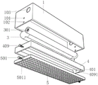
Fig. 3 is an explosion diagram of the overall structure of the present invention.
Fig. 4 is a schematic view of the structure of the heat dissipation pipe of the present invention.
Fig. 5 is a schematic view of the structure of the vapor chamber of the present invention.
Fig. 6 is the utility model discloses a LED lamp split structure schematic diagram.
The reference signs are: 1. a lamp housing; 101. a first through groove; 102. a second through groove; 103. a third through groove; 2. fixing a strut; 201. a fixing cap; 3. a vent pipe; 301. an air outlet fan; 302. an air inlet fan; 4. a temperature equalizing plate; 401. a lamp tube; 402. a lamp post; 403. a dust ring; 404. dustproof glass; 405. a reflector; 406. an LED light emitting element; 407. a heat sink; 408. a lamp shade; 409. a first bolt; 4091. a first through hole; 5. a diffuser plate; 501. a second bolt; 5011. a second via.
Detailed Description
The technical solution of the present invention will be described clearly and completely with reference to the accompanying drawings in the present invention, and the forms of the structures described in the following embodiments are merely examples, and the present invention is not limited to the structures described in the following embodiments, and all other embodiments obtained by a person of ordinary skill in the art without creative work belong to the scope of the present invention.
Referring to fig. 1-5, the utility model provides a LED light is used in classroom, including lamp body 1, first logical groove 101 has been seted up at the middle part of the side of lamp body 1, the first logical groove 101 inboard of seting up in the side of lamp body 1 is equipped with the screw thread, the outside that first logical groove 101 was equipped with first bolt 409, the shank of bolt of first bolt 409 is equipped with the screw thread, first bolt 409 carries out fixed connection through the screw thread of shank of bolt and the inboard screw thread of first logical groove 101, second logical groove 102 has been seted up at the side bottom middle part of lamp body 1, the logical groove 102 inboard of second that the side bottom middle part of lamp body 1 was seted up is equipped with the screw thread, the outside that the logical groove 102 of second was equipped with second bolt 501, the shank of bolt 501 is equipped with the screw thread, second bolt 501 carries out fixed connection through the screw thread of shank of bolt and the inboard screw thread of second logical groove 102, third logical groove 103 has been seted up on the top of lamp body 1 side, the inboard fixedly connected with ventilation pipe 3 is LED to the logical groove 103 of third.
Referring to fig. 1-5, the utility model provides a LED light for classroom, including temperature-uniforming plate 4, first through-hole 4091 has been seted up at the side middle part of temperature-uniforming plate 4, first through-hole 4091 inboard is equipped with the screw thread, the side of temperature-uniforming plate 4 is through the shank of bolt screw of first bolt 409 and the inboard screw thread fixed connection of first through-hole 4091 at the inner wall of lamp body 1, the inner wall of temperature-uniforming plate 4 is at first through-hole 4091 both sides fixedly connected with fluorescent tube 401, the inner wall fixedly connected with lamp pole 402 of fluorescent tube 401, one side fixed connection of lamp pole 402 is at temperature-uniforming plate 4, one side fixedly connected with dustproof glass 404 of temperature-uniforming plate 4 is kept away from to lamp pole 402, dustproof glass 404's 404 outside fixedly connected with dust ring 403, the outside swing joint of dustproof ring 403 is at the inner wall of fluorescent tube 401, one side fixedly connected with reflector 402 is kept away from to dustproof glass 404, the inner chamber middle part fixedly connected with LED light emitting component 406 that dustproof glass 404 one side was kept away from to reflector 405, the lamp shade 405 is connected with lamp shade 405 and is connected with reflector 405 on one side of radiator 408 surface of lamp shade 408.
Referring to fig. 1-5, the utility model provides a LED light is used in classroom still includes diffuser plate 5, and second bolt 501 has been seted up at the side middle part of diffuser plate 5, and second bolt 501 inboard is equipped with the screw thread, and the side of diffuser plate 5 is through the shank of bolt screw thread of second bolt 501 and second through-hole 5011's inboard screw thread fixed connection at the inner wall of lamp body 1.
Referring to fig. 2 and 3, the utility model provides a LED light is used in classroom, including ventilation pipe 3, fixedly connected with air outlet fan 301 in ventilation pipe 3's the air outlet, air outlet fan 301's blade is in the one side that is close to third tee bend 103, fixedly connected with air intake fan 302 in ventilation pipe 3's the air inlet, and air intake fan 302's blade is in the one side of keeping away from third tee bend 103.
Referring to fig. 1, the utility model provides a LED light is used in classroom, including lamp body 1, the top fixedly connected with fixing support post 2 of lamp body 1, fixing support post 2 uses the top middle part of lamp body 1 as the axis, fixing support post 2's outside fixedly connected with locking cap 201, locking cap 201's inner wall fixed connection is at fixing support post 2's top.
Referring to fig. 1-5, the utility model provides a LED illuminating lamp for classroom, including ventilation pipe 3, the bottom fixedly connected with temperature-uniforming plate 4 of ventilation pipe 3, the one side that temperature-uniforming plate 4 is close to fluorescent tube 401 has the wave structure, the bottom fixedly connected with diffuser plate 5 of temperature-uniforming plate 4.
Referring to fig. 1-5, the utility model provides a classroom is with LED light, including the temperature equalization board 4, the inner wall of temperature equalization board 4 scribbles the antireflection coating.
The utility model discloses a theory of operation: when the LED lamp works, the LED light-emitting element 406 converts electric energy into visible light through direct current driving, so that classroom light is emitted and illuminated by the LED lamp, light emitted by the LED light-emitting element 406 is reflected to the lamp tube 401 through the reflector 405, stray light of the light is reduced by the antireflection film of the lamp tube 401, the light-emitting efficiency of the LED light-emitting element 406 is increased, the light reaches the diffusion plate 5, incident light is fully scattered by changing the light traveling route of the diffusion plate 5, a softer and uniform illumination effect is realized, the LED lamp for classrooms does not have the problems of stroboflash and glare, heat generated by the LED light-emitting element 406 in the continuous working process is dissipated by the heat dissipation body 407, the residual heat is absorbed by the temperature equalizing plate 4, at the moment, air is pushed to flow in the same direction as the axis by blades of the air outlet fan 301 and the air inlet fan 302 in the ventilation tube 3, heat dissipation is performed by means of forced thermal convection, heat exchange with ambient air by means of flow guiding effect to carry away the heat, thereby realizing the heat dissipation manner of forced convection, the residual heat is dissipated, the LED light-emitting element 406 is prevented from being damaged by the dust-proof ring 403, and the LED light-emitting element can be well connected with the dust-emitting ring 403, and the dust-emitting element can be prevented from being damaged.
The points to be finally explained are: first, in the description of the present application, it should be noted that, unless otherwise specified and limited, the terms "mounted," "connected," "connecting," and "connecting" should be understood broadly, and may be a mechanical connection or an electrical connection, or a communication between two elements, and may be directly connected, and "upper," "lower," "left," and "right" are only used to indicate relative positional relationships, and when the absolute position of the object to be described is changed, the relative positional relationships may be changed;
secondly, the method comprises the following steps: in the drawings of the disclosed embodiments of the present invention, only the structures related to the disclosed embodiments are referred to, and other structures can refer to common designs, and under the condition of no conflict, the same embodiment and different embodiments of the present invention can be combined with each other;
and finally: the above description is only for the preferred embodiment of the present invention and should not be taken as limiting the invention, and any modifications, equivalent replacements, improvements, etc. made within the spirit and principle of the present invention should be included in the protection scope of the present invention.
Claims (7)
1. The utility model provides a LED light for classroom, includes lamp body (1), its characterized in that: the improved lamp is characterized in that a first through groove (101) is formed in the middle of the side face of the lamp housing (1), threads are arranged on the inner side of the first through groove (101) formed in the side face of the lamp housing (1), a first bolt (409) is arranged on the outer side of the first through groove (101), a bolt rod of the first bolt (409) is provided with threads, the first bolt (409) is fixedly connected with the temperature equalizing plate (4), a second through groove (102) is formed in the middle of the bottom end of the side face of the lamp housing (1), threads are arranged on the inner side of the second through groove (102) formed in the middle of the bottom end of the side face of the lamp housing (1), a second bolt (501) is arranged on the outer side of the second through groove (102), threads are arranged on the bolt rod of the second bolt (501), the second bolt (501) is fixedly connected with the threads of the inner side of the second through groove (102), a diffusion plate (5) is fixedly connected to the bottom inside of the lamp housing (1), a third through groove (3) is fixedly connected with the inner side of the diffusion plate (103).
2. The LED lighting lamp for classroom as claimed in claim 1, wherein: a first through hole (4091) is formed in the middle of the side face of the temperature equalizing plate (4), threads are arranged on the inner side of the first through hole (4091), the side face of the temperature equalizing plate (4) is fixedly connected to the inner wall of the lamp housing (1) through the bolt rod threads of a first bolt (409) and the inner side threads of the first through hole (4091), the inner wall of the temperature equalizing plate (4) is fixedly connected with lamp tubes (401) on the two sides of the first through hole (4091), the inner wall of each lamp tube (401) is fixedly connected with a lamp post (402), one side of each lamp post (402) is fixedly connected to the temperature equalizing plate (4), and one side of each lamp post (402) far away from the temperature equalizing plate (4) is fixedly connected with dustproof glass (404), the utility model discloses a lamp, including lamp tube (401), dustproof glass's (404) outside fixedly connected with dust ring (403), the outside swing joint of dust ring (403) is at the inner wall of fluorescent tube (401), one side fixedly connected with reflector (405) of lamp pole (402) are kept away from in dustproof glass (404), the inner chamber middle part fixedly connected with LED light emitting component (406) of dustproof glass (404) one side is kept away from in reflector (405), the outside swing joint of the inner chamber of dustproof glass (404) one side is kept away from in reflector (405) has radiator (407), inboard fixedly connected with lamp shade (408) of radiator (407), lamp shade (408) are being close to the surface of reflector (405) one side and reflector (405) activity And (4) dynamic connection.
3. The LED lighting lamp for classroom as claimed in claim 1, wherein: second bolt (501) have been seted up at the side middle part of diffuser plate (5), second bolt (501) inboard is equipped with the screw thread, the side of diffuser plate (5) is through the inside screw thread fixed connection of the shank of bolt screw thread of second bolt (501) and second through-hole (5011) at the inner wall of lamp body (1).
4. The LED lighting lamp for classroom as claimed in claim 1, wherein: fixedly connected with air outlet fan (301) in the air outlet of ventilation pipe (3), the blade of air outlet fan (301) is in the one side that is close to third through slot (103), fixedly connected with air intake fan (302) in the air inlet of ventilation pipe (3), the blade of air intake fan (302) is in the one side of keeping away from third through slot (103).
5. The LED lighting lamp for classroom as claimed in claim 1, wherein: the top fixedly connected with fixed pillar (2) of lamp body (1), fixed pillar (2) use the top middle part of lamp body (1) as the axis, the outside fixedly connected with locking cap (201) of fixed pillar (2), the inner wall fixed connection of locking cap (201) is at the top of fixed pillar (2).
6. The LED lighting lamp for classroom as claimed in claim 1, wherein: the bottom end of the ventilation pipe (3) is fixedly connected with a temperature-uniforming plate (4), one surface, close to the lamp tube (401), of the temperature-uniforming plate (4) is of a wave-shaped structure, and the bottom end of the temperature-uniforming plate (4) is fixedly connected with a diffusion plate (5).
7. The LED lighting lamp for classroom as claimed in claim 1, wherein: the inner wall of the temperature equalizing plate (4) is coated with an antireflection film.
Priority Applications (1)
| Application Number | Priority Date | Filing Date | Title |
|---|---|---|---|
| CN202222460230.9U CN218237199U (en) | 2022-09-15 | 2022-09-15 | LED illuminating lamp for classroom |
Applications Claiming Priority (1)
| Application Number | Priority Date | Filing Date | Title |
|---|---|---|---|
| CN202222460230.9U CN218237199U (en) | 2022-09-15 | 2022-09-15 | LED illuminating lamp for classroom |
Publications (1)
| Publication Number | Publication Date |
|---|---|
| CN218237199U true CN218237199U (en) | 2023-01-06 |
Family
ID=84663638
Family Applications (1)
| Application Number | Title | Priority Date | Filing Date |
|---|---|---|---|
| CN202222460230.9U Active CN218237199U (en) | 2022-09-15 | 2022-09-15 | LED illuminating lamp for classroom |
Country Status (1)
| Country | Link |
|---|---|
| CN (1) | CN218237199U (en) |
-
2022
- 2022-09-15 CN CN202222460230.9U patent/CN218237199U/en active Active
Similar Documents
| Publication | Publication Date | Title |
|---|---|---|
| US9791111B1 (en) | LED lighting device having a prolonged life during high temperature operation | |
| US9995471B2 (en) | LED lighting device having a structural design that effectively increases the surface area of the circuit board for circuit layout | |
| US20090213588A1 (en) | Outdoor luminaire using light emitting diodes | |
| US8536807B2 (en) | LED bulb | |
| CN202165954U (en) | Effective heat radiating LED (Light-emitting Diode) eyeshield mining lamp | |
| CN201547610U (en) | Led tunnel lamp device | |
| CN204986520U (en) | Light -emitting diode (LED) energy -saving lamp | |
| JP2011014515A (en) | Lighting fixture excellent on illuminance and light-distribution nature | |
| CN218237199U (en) | LED illuminating lamp for classroom | |
| RU166928U1 (en) | LED LAMP | |
| CN101813276A (en) | Environment friendly high-power LED street lamp | |
| CN208886422U (en) | It can the truncated cone-shaped modularized limit emitting diode (LED) light bulb arbitrarily installed of upper and lower side | |
| CN207049729U (en) | A kind of LED area light source shot-light of easy heat radiation | |
| CN201827770U (en) | LED (light-emitting diode) ceiling lamp | |
| CN204943147U (en) | A kind of mouth lamp light source | |
| RU160784U1 (en) | LED PROJECT LAMP | |
| CN205504723U (en) | LED (Light emitting diode) ceiling lamp | |
| CN220930942U (en) | LED curved lens | |
| CN204806009U (en) | Convection's LED light | |
| CN108626682A (en) | A kind of vehicle laser headlamp | |
| CN208703763U (en) | A kind of down-ejection type anti-glazing LED Line lamp | |
| CN217737011U (en) | Multi-surface light-emitting landscape lighting lamp with anti-glare function | |
| CN211232575U (en) | LED street lamp capable of improving illumination definition | |
| CN214222890U (en) | Anti-dazzle eye protection device for classroom lamp | |
| CN206055279U (en) | The extraordinary LED illumination lamp of the shellproof, super brightness of one kind |
Legal Events
| Date | Code | Title | Description |
|---|---|---|---|
| GR01 | Patent grant | ||
| GR01 | Patent grant |