CN218174383U - Steel pipe hoisting device - Google Patents
Steel pipe hoisting device Download PDFInfo
- Publication number
- CN218174383U CN218174383U CN202222525429.5U CN202222525429U CN218174383U CN 218174383 U CN218174383 U CN 218174383U CN 202222525429 U CN202222525429 U CN 202222525429U CN 218174383 U CN218174383 U CN 218174383U
- Authority
- CN
- China
- Prior art keywords
- steel pipe
- connecting plate
- hanger
- plate
- lifting
- Prior art date
- Legal status (The legal status is an assumption and is not a legal conclusion. Google has not performed a legal analysis and makes no representation as to the accuracy of the status listed.)
- Active
Links
Images


Abstract
The utility model relates to a lifting device technical field especially relates to a steel pipe hoist device. The method comprises the following steps: a hanger and a lifting hook; two ends of the hanger are provided with connecting structures; the connecting structure comprises a connecting plate, and one end of the connecting plate is rotatably connected with the hanging bracket; the number of the lifting hooks is multiple; the lifting hooks are arranged from one end of the connecting plate to the other end; the lifting hook is connected with the connecting plate. In the prior art, bundled steel pipes can be hoisted. But during hoisting, only a single bundle of steel pipes can be hoisted at a time. Therefore, the hoisting efficiency is relatively low. Compared with the prior art, the utility model discloses a rotate the connecting plate, can make the lifting hook suit with the steel pipe of arranging side by side to at hoist and mount in-process, can not excessively extrude between the steel pipe, cause the steel pipe to warp or the bandage fracture. Therefore, the utility model discloses more be applicable to hoist and mount many bundles of steel pipes simultaneously to improve hoist and mount efficiency.
Description
Technical Field
The utility model relates to a lifting device technical field especially relates to a steel pipe hoist device.
Background
In the actual steel pipe production process, after the production of a single steel pipe is completed, a certain number of steel pipes are generally required to be integrated into one bundle in order to facilitate subsequent packaging and transportation. When transporting bundles of steel pipes, corresponding hoisting equipment is needed. The hoisting equipment is only provided with one single lifting hook, and when the steel pipes are hoisted, the hoisting equipment is easily influenced by external factors such as the length of the steel pipes, and the like, so that the problems that the steel pipes are inclined to touch the ground and the like are easily caused when the steel pipes are hoisted into bundles. Therefore, a corresponding hoisting device is needed to be matched with the hoisting equipment.
Chinese patent discloses a steel pipe hoist [ application number: CN201921015083.6, publication No.: CN210763903U includes: the lifting ring, the lifting frame, the hanging strip assembly and the hanging hook assembly; the hoisting ring is arranged in the middle of the hoisting frame; the lifting frame is of a truss structure, the lifting frame is provided with a hanging strip assembly and a hanging hook assembly at two ends, wherein the hanging strip assembly is located on the outer side of the hanging hook assembly, and the hanging strip assembly and the hanging hook assembly are of detachable structures. Although the technical scheme of this patent can play collocation hoisting equipment and carry out the effect of hoist and mount to the steel pipe of bundle, when practical application, the technical scheme of this patent can only hoist a bundle of steel pipe, and hoist and mount efficiency is lower relatively.
SUMMERY OF THE UTILITY MODEL
Technical problem to prior art, the utility model provides a steel pipe hoist device.
In order to solve the technical problem, the utility model provides a following technical scheme:
a steel pipe hoist device includes: a hanger and a hook; connecting structures are arranged at two ends of the hanging bracket; the connecting structure comprises a connecting plate, and one end of the connecting plate is rotatably connected with the hanging bracket; the number of the lifting hooks is multiple; the lifting hooks are distributed from one end of the connecting plate to the other end; the lifting hook is connected with the connecting plate.
For convenience of description, a direction perpendicular to a plane in which the hanger is located is defined as an a direction. In practical application, the hanging bracket is connected with the hoisting equipment. When a plurality of bundles of steel pipes need to be hoisted, a specified number of steel pipes are arranged side by side in advance. The connecting plate is rotated to adjust the included angle between the connecting plate and the hanging bracket, so that the lifting hook on the connecting plate moves to a state adaptive to the steel pipe. At the moment, the lifting hook is connected with the steel pipe, and the steel pipe can be lifted by utilizing the lifting equipment. As mentioned above, when bundles of steel pipes are arranged side by side, the steel pipes are spaced apart from the hanger in the a direction. Through rotating the connecting plate, the interval between lifting hook and the gallows on the multiplicable connecting plate in the A direction to suit with the steel pipe of arranging side by side, and then at the hoist and mount in-process, can not excessively extrude between the steel pipe of bundle, lead to the steel pipe to warp or lead to the bandage fracture that is used for binding the steel pipe. Therefore, the utility model discloses more be applicable to hoist and mount many bundles of steel pipes simultaneously.
Further, the hanging bracket is triangular; a plurality of reinforcing ribs are arranged in the hanging bracket.
Furthermore, a butt joint structure is arranged at one end of the hanging bracket, which is far away from the ground; the butt joint structure comprises a main butt joint ring and a side butt joint ring; the side butt joint rings are respectively arranged at two sides of the main butt joint ring; the side butt joint ring is sleeved on the hanging bracket; the side butt joint ring is sleeved on the main butt joint ring; the main butt joint ring is used for being connected with hoisting equipment.
Furthermore, the length of the lifting hook is increased progressively from one end of the connecting plate close to the hanging bracket to one end far away from the hanging bracket.
Furthermore, the connecting structure also comprises a positioning pin; the positioning pin penetrates through the end part of the hanger; one end of the connecting plate is rotatably connected with the end part of the hanger through a positioning pin.
Furthermore, the number of the connecting plates positioned at the same end of the hanging bracket is two; a rotating plate is arranged on the connecting plate and sleeved on the positioning pin; one of the connecting plates is provided with a position yielding plate; the yielding plate is connected with the connecting plate; the position plate is connected with the corresponding rotating plate.
Furthermore, the rotation directions of the two connecting plates at the same end of the hanger are opposite.
Compared with the prior art, the utility model has the advantages of it is following:
through the adjustable lifting hook motion of connecting plate to the position corresponding with the steel pipe to alleviate the extrusion between the steel pipe to a certain extent, can avoid the steel pipe to take place uncontrollable deformation because of the extrusion on the one hand, on the other hand can effectively prevent to be used for binding the bandage of steel pipe and take place the fracture. Therefore, the utility model discloses more be applicable to hoist and mount many bundles of steel pipes simultaneously, help improving hoist and mount efficiency.
Drawings
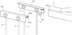
FIG. 1: the overall structure diagram.
FIG. 2: the structure diagram of the butt joint structure.
FIG. 3: and (4) connecting structure explosion diagram.
FIG. 4: connection structure chart.
FIG. 5: the connection structure is combined with the schematic diagram.
FIG. 6: the connecting structure is expanded and shown schematically.
In the figure: 1. a hanger; 11. a connecting structure; 12. reinforcing ribs; 13. a butt joint structure; 131. a primary docking ring; 132. a side docking ring; 111. a connecting plate; 112. positioning pins; 1111. a rotating plate; 1112. a position yielding plate; 2. and (4) a lifting hook.
Detailed Description
The following are specific embodiments of the present invention and the accompanying drawings are used to further describe the technical solution of the present invention, but the present invention is not limited to these embodiments.
A steel pipe hoist device includes: hanger 1, lifting hook 2. The hanger 1 is composed of a steel bar with a circular section and a rectangular hollow steel pipe. The two parts form a triangular structure together, so that the hanger 1 has strong structural stability. Be provided with a plurality of strengthening ribs 12 in circular reinforcing bar and the synthetic triangle-shaped region of rectangle hollow steel pipe enclosure for further strengthen the structural strength of gallows 1 self, take place uncontrollable deformation or fracture with the gallows 1 in order to avoid in the use.
The end of the hanger 1 far away from the ground is provided with a butt joint structure 13. The docking structure 13 includes a main docking ring 131 and a side docking ring 132. The number of side abutment rings 132 is two. The side docking rings 132 are respectively disposed at both sides of the main docking ring 131. The side docking collar 132 is fitted over the hanger 1 and adjusted to the main docking collar 131. Thus, the main docking ring 131 and the side docking ring 132 are triangularly arranged, thereby providing a certain degree of structural stability. The device can be connected with the hoisting equipment by penetrating the hook of the hoisting equipment through the main butt-joint ring 131.
Both ends of the hanger 1 are also provided with connecting structures 11. The connecting structure 11 includes a connecting plate 111 and a positioning pin 112. The positioning pin 112 is disposed in and penetrates the rectangular hollow steel pipe of the hanger 1. The connection plate 111 itself is approximately L-shaped. One end of the connection plate 111 is rotatably connected to the hanger 1 by a positioning pin 112. In particular, the number of connecting plates 111 located at the same end of the cradle 1 is two. One end of the connecting plate 111 is provided with a rotating plate 1111, and the rotating plate 1111 can be rotatably sleeved on the positioning pin 112. So that the connection plate 111 can rotate about the positioning pin 112. A position-giving plate 1112 is further arranged on one of the connecting plates 111. The abdicating plate 1112 is arc-shaped corresponding to the rotating plate 1111, so that the abdicating plate 1112 can be attached to the non-connected rotating plate 1111. The holding plate 1112 is connected to the connecting plate 111 and to the corresponding rotating plate 1111. The use of the abdicating plate 1112 enables the two rotating plates 1111 to be stacked on the positioning pin 112 from top to bottom, so that the two rotating plates 1111 do not interfere with each other when rotating. On the other hand, the link plates 111 at the same end of the hanger 1 are rotated in opposite directions, and when the link plates 111 are rotated to a state perpendicular to the plane of the hanger 1, the link plates 111 are rotated to a maximum angle. At this time, the two connection plates 111 interfere with the ends of the hanger 1, so that the connection plates 111 cannot rotate any further.
A plurality of bolts are arranged on the connecting plate 111, and the bolts are uniformly distributed to the other end from one end of the connecting plate 111. The lifting hooks 2 correspond to the bolts one by one. The lifting hook 2 is provided with a steel cable structure which can be sleeved on the bolt. Through install the nut additional on the bolt for the nut extrudees the steel cable structure, thereby makes the steel cable structure fully laminate with the lateral wall of connecting plate 111, and then makes steel cable structure and connecting plate 111 fully connected. Meanwhile, the length of the steel cable changes along with the position of the hook 2, and the length of the steel cable increases from the end of the connecting plate 111 close to the hanger 1 to the end far away from the hanger 1.
For convenience of description, a direction perpendicular to the plane of the hanger 1 will be defined as an a direction. When in actual application, will through butt-joint structure 13 the utility model discloses be connected with lifting device's couple. When the bundled steel pipes need to be hoisted, a plurality of bundles of steel pipes are placed below the hoisting frame 1 side by side. At this time, the steel pipe is spaced apart from the hanger 1 in the a direction. Toggle connecting plate 111 to make connecting plate 111 use locating pin 112 to swing for gallows 1 as the axle, thereby the contained angle between adjustment connecting plate 111 and the gallows 1, and then the interval between one end that adjustment connecting plate 111 kept away from gallows 1 and gallows 1 in the A direction. When the rotation angle is gradually increased from 0 ° to 90 °, the distance between one end of the connecting plate 111, which is far away from the hanger 1, and the hanger 1 in the direction a is gradually increased, and when the included angle between the connecting plate 111 and the hanger 1 is 90 °, the distance reaches the maximum value.
When the connecting plate 111 rotates, the lifting hook 2 is driven to move synchronously, and then the distance between the lifting hook 2 and the hanger 1 in the direction A is adjusted. Thereby, the position state of the hook 2 can be adapted to the position of the steel pipe. When the connecting plate 111 is rotated to a proper position, the hook 2 can be connected with the steel pipe. At this time, the steel pipe is hoisted by the hoisting equipment. After the steel pipe is lifted, an included angle exists between the steel cable on the lifting hook 2 and the vertical direction, and the pulling force applied to the steel pipe by the lifting hook 2 is along the direction of the steel cable, so that the included angle exists between the pulling force applied by the lifting hook 2 and the gravity direction. Therefore, the component force of the pulling force in the vertical direction is used to overcome the gravity of the steel pipe, so that the steel pipe is hoisted. The horizontal component of the pulling force will force the steel pipes to be squeezed together. The size of the included angle between the steel cable and the gravity direction can be effectively reduced through the process of adjusting the connecting plate 111, so that the component force of the pulling force applied to the steel pipe by the lifting hook 2 in the horizontal direction is reduced, the mutual extrusion between the steel pipes is further reduced, and the steel pipe deformation or the breakage of a binding belt for binding the steel pipe caused by excessive extrusion is avoided. Meanwhile, the length of the steel cable of the hook 2 at one end of the connecting plate 111 far away from the hanger 1 is the longest, the distance between the steel pipe at the outermost side and the hanger 1 in the direction a increases with the number of steel pipe bundles, and the connection between the hook 2 and the steel pipe is facilitated through the steel cable with the longer length.
Preferably, a damping structure is added to the positioning pin 112 to prevent the connecting plate 111 from swinging uncontrollably during the hoisting process.
The specific embodiments described herein are merely illustrative of the spirit of the invention. Various modifications, additions and substitutions for the specific embodiments described herein may be made by those skilled in the art without departing from the spirit of the invention or exceeding the scope of the invention as defined in the accompanying claims.
Claims (7)
1. The utility model provides a steel pipe hoist device which characterized in that: the method comprises the following steps: a hanger (1) and a lifting hook (2);
two ends of the hanger (1) are provided with connecting structures (11);
the connecting structure (11) comprises a connecting plate (111), and one end of the connecting plate (111) is rotatably connected with the hanging bracket (1);
the number of the lifting hooks (2) is multiple;
the lifting hooks (2) are arranged from one end of the connecting plate (111) to the other end;
the lifting hook (2) is connected with the connecting plate (111).
2. The steel pipe hoisting device according to claim 1, characterized in that: the hanging bracket (1) is triangular;
a plurality of reinforcing ribs (12) are arranged in the hanging bracket (1).
3. The steel pipe hoisting device according to claim 1, characterized in that: a butt joint structure (13) is arranged at one end of the hanger (1) far away from the ground;
the docking structure (13) comprises a main docking ring (131), a side docking ring (132);
the side docking rings (132) are respectively arranged at both sides of the main docking ring (131);
the side butt joint ring (132) is sleeved on the hanger (1);
the side butt joint ring (132) is sleeved on the main butt joint ring (131);
the main butt joint ring (131) is used for being connected with hoisting equipment.
4. The steel pipe hoisting device according to claim 1, characterized in that: the length of the lifting hook (2) is increased progressively from one end of the connecting plate (111) close to the hanging bracket (1) to one end far away from the hanging bracket (1).
5. The steel pipe hoisting device according to claim 1, characterized in that: the connecting structure (11) further comprises a positioning pin (112);
the positioning pin (112) penetrates through the end part of the hanger (1);
one end of the connecting plate (111) is rotatably connected with the end part of the hanging bracket (1) through the positioning pin (112).
6. The steel pipe hoisting device according to claim 5, characterized in that: the number of the connecting plates (111) at the same end of the hanger (1) is two;
a rotating plate (1111) is arranged on the connecting plate (111), and the rotating plate (1111) is sleeved on the positioning pin (112);
one of the connecting plates (111) is provided with a position-giving plate (1112);
the position-giving plate (1112) is connected with the connecting plate (111);
the position-giving plate (1112) is connected with the corresponding rotating plate (1111).
7. The steel pipe hoisting device according to claim 6, characterized in that: the rotation directions of the two connecting plates (111) at the same end of the hanger (1) are opposite.
Priority Applications (1)
| Application Number | Priority Date | Filing Date | Title |
|---|---|---|---|
| CN202222525429.5U CN218174383U (en) | 2022-09-23 | 2022-09-23 | Steel pipe hoisting device |
Applications Claiming Priority (1)
| Application Number | Priority Date | Filing Date | Title |
|---|---|---|---|
| CN202222525429.5U CN218174383U (en) | 2022-09-23 | 2022-09-23 | Steel pipe hoisting device |
Publications (1)
| Publication Number | Publication Date |
|---|---|
| CN218174383U true CN218174383U (en) | 2022-12-30 |
Family
ID=84625308
Family Applications (1)
| Application Number | Title | Priority Date | Filing Date |
|---|---|---|---|
| CN202222525429.5U Active CN218174383U (en) | 2022-09-23 | 2022-09-23 | Steel pipe hoisting device |
Country Status (1)
| Country | Link |
|---|---|
| CN (1) | CN218174383U (en) |
Cited By (1)
| Publication number | Priority date | Publication date | Assignee | Title |
|---|---|---|---|---|
| CN116281568A (en) * | 2023-05-25 | 2023-06-23 | 山东锐华氟业有限公司 | Hoisting device for hoisting sulfur tetrafluoride |
-
2022
- 2022-09-23 CN CN202222525429.5U patent/CN218174383U/en active Active
Cited By (2)
| Publication number | Priority date | Publication date | Assignee | Title |
|---|---|---|---|---|
| CN116281568A (en) * | 2023-05-25 | 2023-06-23 | 山东锐华氟业有限公司 | Hoisting device for hoisting sulfur tetrafluoride |
| CN116281568B (en) * | 2023-05-25 | 2023-07-28 | 山东锐华氟业有限公司 | Hoisting device for hoisting sulfur tetrafluoride |
Similar Documents
| Publication | Publication Date | Title |
|---|---|---|
| EP2639196B1 (en) | TOWER CRANE AND TIE ROD STRUCTURE of balance boom THEREOF, AND method for MOUNTING tie rod structure of balance boom | |
| CN218174383U (en) | Steel pipe hoisting device | |
| CN203247012U (en) | Composite insulator hoisting fixture | |
| CN107381329A (en) | Automatic hook block | |
| CN209024048U (en) | A kind of high stability tubing derrick crane | |
| CN206680061U (en) | A kind of gravity type board suspending frame | |
| CN213059833U (en) | Standard container hoist and mount auxiliary device | |
| CN109110634A (en) | A kind of high stability tubing derrick crane | |
| CN207192580U (en) | It is a kind of can automatic centering metering new steel plate suspension bracket | |
| CN109399470A (en) | A kind of folding-jib hanging device | |
| WO2021109532A1 (en) | Dual-arm robot for pipe processing, and pipe processing system | |
| CN113911904A (en) | Steel arch rib single-hook air turning-over device and using method thereof | |
| CN109050376B (en) | Building assembly transmission device | |
| JP2012189078A (en) | Method for detaching torque converter and starting motor from auxiliary compartment of gas turbine | |
| CN207390190U (en) | A kind of easy tubing transporter | |
| CN207117044U (en) | Electric aerial work servicing unit | |
| CN207713240U (en) | A kind of magnetic force boom hoisting suitable for different size steel plates | |
| CN206857955U (en) | Brake type sling upper rack and crane | |
| CN207566736U (en) | Transport device is fixed convenient for the building steel tube of assembling | |
| CN201850091U (en) | Tower crane and balance arm pull rod structure thereof | |
| CN206476710U (en) | Fork truck hoisting apparatus | |
| CN215828146U (en) | Coincide floor hoist | |
| CN215630138U (en) | Auxiliary pipe lifting device for steel shell immersed tube pouring pipeline | |
| CN220787860U (en) | Portal crane convenient to reinforcing bar processing | |
| CN110654990B (en) | Metal pipe fitting overhead hoist for engineering construction |
Legal Events
| Date | Code | Title | Description |
|---|---|---|---|
| GR01 | Patent grant | ||
| GR01 | Patent grant |