CN218161458U - Novel box-type 10kV transformer substation box body - Google Patents
Novel box-type 10kV transformer substation box body Download PDFInfo
- Publication number
- CN218161458U CN218161458U CN202221502127.XU CN202221502127U CN218161458U CN 218161458 U CN218161458 U CN 218161458U CN 202221502127 U CN202221502127 U CN 202221502127U CN 218161458 U CN218161458 U CN 218161458U
- Authority
- CN
- China
- Prior art keywords
- box
- layer board
- load layer
- support track
- support
- Prior art date
- Legal status (The legal status is an assumption and is not a legal conclusion. Google has not performed a legal analysis and makes no representation as to the accuracy of the status listed.)
- Active
Links
Images


Abstract
The utility model discloses a novel 10kV box-type substation box, the upper surface of base is provided with the box, fixedly connected with support track in the box, sliding connection has the load layer board on the support track, fixedly connected with distribution equipment on the load layer board, the spout has all been seted up to every support orbital upper surface, all rotates in the spout and is connected with the threaded rod, equal threaded connection has the drive block on the threaded rod, drive block sliding connection is in support orbital spout, the lower fixed surface of drive block and load layer board is connected, the utility model discloses a set up the load layer board, the hand rim plate of rotatory side can slide the load layer board and extend to the box outside, conveniently hoist distribution equipment on the load layer board, and it is internal to slide distribution equipment into along with the load layer board again, not only laborsaving and convenient operation to realize easy to assemble and the later maintenance's of being convenient for effect, it is more convenient to use.
Description
Technical Field
The utility model relates to a distributor technical field specifically is a novel box-type substation box of 10 kV.
Background
The box-type transformer substation, also called combined transformer substation, is a new type complete equipment capable of deep going into load centre and used for receiving and distributing power, and is characterized by that it integrates the primary electric equipment, such as high-voltage switch equipment, power transformer, low-voltage switch equipment, fan and heater, etc. and secondary electric equipment, such as reactive power compensator, watt-hour meter, temp. condensation controller and telecontrol communication device, and these equipments are mounted in a container whose exterior form is "box", and said equipment has no enclosure wall, house, cable and framework, and possesses the advantages of small floor area, short field mounting time, convenient movement and beautiful appearance.
Because the integration level of the internal control equipment of the transformer substation is high, the combination and installation are heavy, and the integration equipment is difficult to feed into the box body when the common box body is packaged, so that the installation is inconvenient and inconvenient, and a large amount of manpower is consumed.
SUMMERY OF THE UTILITY MODEL
An object of the utility model is to provide a novel box-type substation box of 10kV to solve the problem that proposes in the above-mentioned background art.
In order to realize the above-mentioned purpose, the utility model relates to a novel box-type substation of 10kV, the on-line screen storage device comprises a base, the upper surface of base is provided with the box, fixedly connected with support track in the box, sliding connection has the load layer board on the support track, every load layer board left and right sides is connected with two support tracks respectively, two support tracks respectively fixed connection on two sides in the box, fixedly connected with distribution equipment on the load layer board, the spout has all been seted up to every support track's upper surface, it is connected with the threaded rod all to rotate in the spout, equal threaded connection has the drive block on the threaded rod, drive block sliding connection is in support track's spout, the lower fixed surface of drive block and load layer board is connected.
The threaded rod can drive the load layer board to slide and extend to the outside of the box body, the distribution equipment is conveniently hoisted on the load layer board, and then the distribution equipment slides into the box body along with the load layer board, so that the labor is saved, the operation is convenient, the convenience in installation and the later maintenance are realized, and the use is more convenient.
Furthermore, the lower surface of the load supporting plate is fixedly connected with two supporting plates, and sliding extension plates are connected between the two supporting plates and the two supporting rails in a sliding mode.
Furthermore, the both sides of every slip extension board fixed mounting respectively have first T type piece and second T type piece, T type spout has all been seted up with every orbital opposite side of support to every backup pad, first T type piece sliding connection is in the orbital T type spout of support, second T type piece sliding connection is in the T type spout of backup pad.
The setting of backup pad and extension board is at the state that the load layer board stretches out, and the slip extension board supports the bottom of load layer board, improves the stability of load layer board, makes it adapt to more stable and safety.
Furthermore, the transmission assembly comprises a connecting rod, the connecting rod is rotatably connected in the box body, two first bevel gears are fixedly connected to two ends of the connecting rod respectively, the front ends of threaded rods in the sliding grooves of the two supporting tracks extend out of the supporting tracks, the front ends of the two threaded rods extending out of the supporting tracks are connected with second bevel gears, and the two second bevel gears are meshed with the two first bevel gears respectively.
Furthermore, one end of the connecting rod extends out of the outer side of the box body, and one end of the connecting rod extending out of the outer side of the box body is fixedly connected with a hand wheel disc.
Through setting up drive assembly, utilize the meshing transmission of first bevel gear and second bevel gear, make and rotate the hand wheel dish and can control the rotation of the support track internal threaded rod of both sides simultaneously, drive the steady spout of load layer board.
Further, the inside fixed mounting of box has a plurality of division boards, and a plurality of division boards set up along box direction of height linearity, and a plurality of cavities are separated into with the box to a plurality of division boards, all are connected with the load layer board in every cavity, and every load layer board all is connected with two support tracks, all is connected with threaded rod and transmission assembly on every support track, all is connected with the hand wheel on every transmission assembly's the connecting rod, all is connected with the backup pad on every load layer board, all is connected with the slip extension board between every backup pad and every support track.
Furthermore, the front surface of the box body is hinged with a box door.
Advantageous effects
The utility model discloses possess following beneficial effect:
1. the utility model has the advantages that by arranging the load supporting plate, the hand wheel disc on the rotating side can slide and extend the load supporting plate to the outside of the box body, so that the power distribution equipment can be conveniently hoisted on the load supporting plate, and then slide into the box body along with the load supporting plate, thereby saving labor and being convenient to operate, realizing the effects of convenient installation and later maintenance, and being more convenient to use;
2. the utility model discloses a set up drive assembly, utilize the meshing transmission of first bevel gear and second bevel gear, make the support track that rotates hand wheel dish can simultaneous control both sides, drive the steady spout of load layer board, through setting up the slip extension board, at the state that the load layer board stretches out, the slip extension board supports the bottom of load layer board, improves the stability of load layer board, makes it adapt to more stable and safety.
Drawings
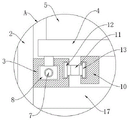
FIG. 1 is a schematic view of a front cross-sectional structure of the present invention;
FIG. 2 is an enlarged schematic view of the structure at A of FIG. 1 according to the present invention;
FIG. 3 is a schematic view of the top-down structure of the present invention;
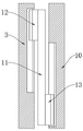
fig. 4 is a schematic top view of the sliding extension plate of the present invention.
In the figure: the automatic loading device comprises a base 1, a box body 2, a supporting track 3, a loading supporting plate 4, a power distribution device 5, a threaded rod 7, a driving block 8, a handwheel 9, a supporting plate 10, a sliding extension plate 11, a first T-shaped block 12, a second T-shaped block 13, a connecting rod 14, a first bevel gear 15, a second bevel gear 16, a partition plate 17 and a box door 18.
Detailed Description
Please refer to fig. 1-4, the utility model relates to a novel box-type substation box of 10kV, including base 1, base 1's upper surface is provided with box 2, fixedly connected with support track 3 in the box 2, sliding connection has load layer board 4 on the support track 3, the 4 left and right sides of every load layer board is connected with two support track 3 respectively, two support track 3 respectively fixed connection are on two sides in box 2, fixedly connected with distribution equipment 5 on the load layer board 4, the spout has all been seted up to every support track 3's upper surface, it is connected with threaded rod 7 all to rotate in the spout, equal threaded connection has drive block 8 on the threaded rod 7, 8 sliding connection of drive block is in support track 3's spout, drive block 8 is connected with the lower fixed surface of load layer board 4.
Rotating threaded rod 7 can drive load layer board 4 and slide and extend to 2 outsides of box, conveniently hoist and mount distribution equipment 5 on load layer board 4, slide distribution equipment 5 into box 2 along with load layer board 4 again, not only laborsaving but also convenient operation to realize easy to assemble and the later maintenance's of being convenient for effect, it is more convenient to use.
The lower surface of the load supporting plate 4 is fixedly connected with two supporting plates 10, and sliding extending plates 11 are connected between the two supporting plates 10 and the two supporting tracks 3 in a sliding manner.
The two sides of each sliding extension plate 11 are respectively and fixedly provided with a first T-shaped block 12 and a second T-shaped block 13, the opposite sides of each support plate 10 and each support rail 3 are respectively provided with a T-shaped sliding groove, the first T-shaped blocks 12 are slidably connected in the T-shaped sliding grooves of the support rails 3, and the second T-shaped blocks 13 are slidably connected in the T-shaped sliding grooves of the support plates 10.
Through setting up slip extension plate 11, at the state that load layer board 4 stretched out, slip extension plate 11 supports the bottom of load layer board 4, improves load layer board 4's stability, makes it adapt to more stably and safety.
Still including transmission assembly, transmission assembly is including connecting rod 14, and connecting rod 14 rotates to be connected in box 2, and two first bevel gear 15 of connecting rod 14 both ends difference fixedly connected with, the threaded rod 7 front end in two 3 spouts of support track all stretches out support track 3, and the front end that two threaded rod 7 stretch out support track 3 all is connected with second bevel gear 16, and two second bevel gear 16 mesh with two first bevel gear 15 respectively.
One end of the connecting rod 14 extends out of the outer side of the box body 2, and one end of the connecting rod 14 extending out of the outer side of the box body 2 is fixedly connected with a hand wheel disc 9.
Through setting up the transmission assembly, utilize the meshing transmission of first bevel gear 15 and second bevel gear 16, make the rotatory hand wheel dish 9 can control the rotation of the support track 3 internal thread pole 7 of both sides simultaneously, drive the steady spout of load layer board 4.
The inside fixed mounting of box 2 has a division board 17, and division board 17 separates into a plurality of cavities with box 2, all is connected with load layer board 4 in every cavity, and every load layer board 4 all is connected with two support tracks 3, all is connected with threaded rod 7 and transmission assembly on every support track 3, all is connected with the hand wheel on every transmission assembly's the connecting rod 14, all is connected with backup pad 10 on every load layer board 4, all is connected with slip extension board 11 between every backup pad 10 and every support track 3.
The front surface of the box body 2 is hinged with a box door 18.
The utility model discloses when using, lay box 2 in the place of use, manual rotation hand rim plate 9, through connecting rod 14, first bevel gear 15 and second bevel gear 16's transmission, it is rotatory to drive threaded rod 7, threaded rod 7 of both sides rotates in step, make two drive blocks 8 drive load layer board 4 extend the box 2 outside, then, slide extension plate 11 also follows the roll-off of load layer board 4 thereupon, and it is outside to extend box 2, support the enhancement to the lower surface of load layer board 4, lift by crane equipment with integrated distribution equipment 5 utilization, press and fix on load layer board 4, reverse rotation hand rim plate 9, make load layer board 4 slide into in box 2 with distribution equipment 5 together, then with load layer board 4 fixed connection in box 2, the same reason, during later maintenance, can stretch out box 2 with load layer board 4 and operate outward, the field of vision is wide, and convenient for the installer's equipment and dismantlement has been greatly made things convenient for this design, and convenience is provided for later maintenance simultaneously, and easy operation, be worth promoting.
Claims (7)
1. The utility model provides a novel box-type substation box of 10kV which characterized in that: including base (1), the upper surface of base (1) is provided with box (2), fixedly connected with support track (3) in box (2), sliding connection has load layer board (4) on support track (3), every load layer board (4) left and right sides is connected with two support track (3) respectively, two support track (3) are fixed connection on two sides in box (2) respectively, fixedly connected with distribution equipment (5) on load layer board (4), the spout has all been seted up to the upper surface of every support track (3), it is connected with threaded rod (7) all to rotate in the spout, equal threaded connection has drive block (8) on threaded rod (7), drive block (8) sliding connection is in the spout of support track (3), the lower fixed surface of drive block (8) and load layer board (4) is connected.
2. The novel box-type substation box of 10kV of claim 1, characterized in that: the lower surface of the load supporting plate (4) is fixedly connected with two supporting plates (10), and sliding extension plates (11) are connected between the two supporting plates (10) and the two supporting rails (3) in a sliding mode.
3. The novel box-type substation box of 10kV of claim 2, characterized in that: the two sides of each sliding extension plate (11) are respectively and fixedly provided with a first T-shaped block (12) and a second T-shaped block (13), the opposite sides of each support plate (10) and each support rail (3) are respectively provided with a T-shaped sliding groove, the first T-shaped blocks (12) are slidably connected in the T-shaped sliding grooves of the support rails (3), and the second T-shaped blocks (13) are slidably connected in the T-shaped sliding grooves of the support plates (10).
4. A novel 10kV box substation box according to any of claims 1-3, characterized in that: still including transmission assembly, transmission assembly is including connecting rod (14), connecting rod (14) rotate to be connected in box (2), two first bevel gears (15) of connecting rod (14) both ends difference fixedly connected with, threaded rod (7) front end in two support track (3) spouts all stretches out support track (3), the front end that two threaded rod (7) stretch out support track (3) all is connected with second bevel gear (16), two second bevel gear (16) mesh with two first bevel gear (15) respectively.
5. The novel box-type substation box of 10kV of claim 4, characterized in that: one end of the connecting rod (14) extends out of the outer side of the box body (2), and one end of the connecting rod (14) extending out of the outer side of the box body (2) is fixedly connected with a hand wheel disc (9).
6. The novel box-type substation box of 10kV of claim 5, characterized in that: the inside fixed mounting of box (2) has a plurality of division boards (17), box (2) direction of height linear setting is followed in a plurality of division boards (17), a plurality of cavities are separated into with box (2) in a plurality of division boards (17), all be connected with load layer board (4) in every cavity, every load layer board (4) all are connected with two support track (3), all be connected with threaded rod (7) and transmission assembly on every support track (3), all be connected with the hand wheel on connecting rod (14) of every transmission assembly, all be connected with backup pad (10) on every load layer board (4), all be connected with between every backup pad (10) and every support track (3) and slide extension board (11).
7. A new type of 10kV box substation box according to any of claims 1, 2, 3, 5 or 6, characterized in that: the front surface of the box body (2) is hinged with a box door (18).
Priority Applications (1)
| Application Number | Priority Date | Filing Date | Title |
|---|---|---|---|
| CN202221502127.XU CN218161458U (en) | 2022-06-16 | 2022-06-16 | Novel box-type 10kV transformer substation box body |
Applications Claiming Priority (1)
| Application Number | Priority Date | Filing Date | Title |
|---|---|---|---|
| CN202221502127.XU CN218161458U (en) | 2022-06-16 | 2022-06-16 | Novel box-type 10kV transformer substation box body |
Publications (1)
| Publication Number | Publication Date |
|---|---|
| CN218161458U true CN218161458U (en) | 2022-12-27 |
Family
ID=84574545
Family Applications (1)
| Application Number | Title | Priority Date | Filing Date |
|---|---|---|---|
| CN202221502127.XU Active CN218161458U (en) | 2022-06-16 | 2022-06-16 | Novel box-type 10kV transformer substation box body |
Country Status (1)
| Country | Link |
|---|---|
| CN (1) | CN218161458U (en) |
-
2022
- 2022-06-16 CN CN202221502127.XU patent/CN218161458U/en active Active
Similar Documents
| Publication | Publication Date | Title |
|---|---|---|
| CN111092390B (en) | Handcart-type is erection equipment for cubical switchboard | |
| CN206976873U (en) | A kind of fixed installation structure of high-tension switch cabinet | |
| CN201990442U (en) | Lifting transfer vehicle | |
| CN208914052U (en) | A kind of distribution box maintenance platform convenient for lifting | |
| CN214013592U (en) | High-low voltage power distribution cabinet hoisting device | |
| CN218161458U (en) | Novel box-type 10kV transformer substation box body | |
| CN207819195U (en) | A kind of electric power cabinet having a safety feature | |
| CN212935404U (en) | Power supply line cross arm suspension frame | |
| CN208874154U (en) | A kind of Multi-function overhaul platform | |
| CN208782350U (en) | A kind of box-type substation convenient for stablizing movement | |
| CN209823134U (en) | High-low voltage power distribution cabinet | |
| CN218058311U (en) | Assembly lifting equipment for electric locomotive driving unit | |
| CN215497831U (en) | Conveniently adjusted middle wire walking step control cabinet | |
| CN211930011U (en) | Supporting device convenient to maintain and used for box-type substation | |
| CN216289731U (en) | Multifunctional indoor high-voltage switch cabinet with high compatibility | |
| CN108631171B (en) | Switch cabinet with high-efficiency heat dissipation performance | |
| CN208189381U (en) | A kind of transformer fe core apparatus | |
| CN215730450U (en) | Insulating experimental apparatus of set formula shunt capacitance ware | |
| CN215868882U (en) | Box-type transformer fixing structure of wind driven generator | |
| CN217934759U (en) | Installation auxiliary device of cubical switchboard | |
| CN201966614U (en) | Novel rural power grids voltage quality regulation equipment | |
| CN205335686U (en) | Switching station base | |
| CN217848635U (en) | Instrument room structure of high-voltage switch cabinet | |
| CN214284244U (en) | Building electrical wiring design display device | |
| CN210723929U (en) | Handcart is transported to centrally installed switchgear in regulation formula |
Legal Events
| Date | Code | Title | Description |
|---|---|---|---|
| GR01 | Patent grant | ||
| GR01 | Patent grant |