CN218156916U - Rock and ore deposit detects with smashing sampler - Google Patents
Rock and ore deposit detects with smashing sampler Download PDFInfo
- Publication number
- CN218156916U CN218156916U CN202222097393.5U CN202222097393U CN218156916U CN 218156916 U CN218156916 U CN 218156916U CN 202222097393 U CN202222097393 U CN 202222097393U CN 218156916 U CN218156916 U CN 218156916U
- Authority
- CN
- China
- Prior art keywords
- fixed
- case
- convex block
- top end
- frame
- Prior art date
- Legal status (The legal status is an assumption and is not a legal conclusion. Google has not performed a legal analysis and makes no representation as to the accuracy of the status listed.)
- Active
Links
Images


Landscapes
- Crushing And Grinding (AREA)
Abstract
The utility model belongs to the technical field of smash the sample, especially, be a rock ore deposit detects uses crushing sampler, the load port has been seted up on the top of machine case, the inside of machine case is fixed with the frame, frame bottom four corners all is fixed with the supporting leg, the top of frame is fixed with fixed convex block, the top of fixed convex block is fixed with two first fixed blocks, two first fixed block symmetry laminatings are in the inner wall department of machine case, first recess has all been seted up to two first fixed blocks, first motor is installed on the top of fixed convex block, install first grinder between two first fixed blocks, put into the load port with the stone again, have in the pay-off process some rocks of unavoidable and drop on the top of sliding plate, at this moment reuse catch bar, impel the load port with the stone in, the stone after smashing can drop on a flitch, go out the flitch and be 45 installations, then can directly flow from the discharge gate.
Description
Technical Field
The utility model belongs to the technical field of smash the sample, concretely relates to rock ore deposit detects with smashing sampler.
Background
The ore is generally composed of ore minerals and gangue minerals. Ore minerals are metal or non-metal minerals that can be utilized in the ore, also known as valuable minerals. Such as chromite in chromium ore, chalcopyrite, bornite, chalcocite and malachite in copper ore, asbestos in asbestos ore, etc. Gangue minerals are those minerals associated with ore minerals that are temporarily unusable, also referred to as unusable minerals. Such as olivine and pyroxene in chromium ore, quartz, sericite and chlorite in copper ore, dolomite and calcite in asbestos ore, etc. Gangue minerals are mainly non-metal minerals, but also include some metal minerals, such as copper ore containing a very small amount of galena and sphalerite, and are also called gangue minerals because of no comprehensive utilization value. The weight ratio of the ore mineral and the gangue mineral contained in the ore varies with different metal ores.
According to the service conditions of difference, need smash the granule with equidimension with the ore, at the in-process of smashing the ore, utilize the high-speed relative motion between the crushing fluted disc, the material that is smashed receives comprehensive action such as impact, friction and material impact each other between the tooth space and obtains smashing, traditional smashing all is fixed kibbling, can't adjust kibbling size at will, can only carry out the crushing of single size particle diameter, and the function is single, can not satisfy present ore crushing demand.
SUMMERY OF THE UTILITY MODEL
For solving the above-mentioned problem that exists among the prior art, the utility model provides a rock ore deposit detects uses crushing sampler has the kibbling characteristics of regulation.
In order to achieve the above purpose, the utility model provides a following technical scheme: a crushing sampler for rock and ore detection comprises a case, wherein the top end of the case is provided with a feeding hole, a frame is fixed in the case, supporting legs are fixed at four corners of the bottom end of the frame, a fixed convex block is fixed at the top end of the frame, two first fixed blocks are fixed at the top ends of the fixed convex blocks, the two first fixed blocks are symmetrically attached to the inner wall of the case, the two first fixed blocks are both provided with a first groove, the top ends of the fixed convex blocks are provided with first motors, a first grinder is arranged between the two first fixed blocks, the output end of the first motor passes through the first grinder and the two first grooves to be attached to the inner wall of the case, the top end of the case is provided with a movable convex block, the convex part of the movable convex block is jointed with the inner wall of the frame, two second fixed blocks are fixed at the top end of the movable convex block and symmetrically attached to the inner wall of the case, the two second fixed blocks are provided with second grooves, the top ends of the movable convex blocks are provided with second motors, the output end of the second motor passes through the two second grooves and the second crusher to be attached to the inner wall of the case, a semicircular block is fixed at the top end of the frame, one side of the semicircular block is attached to the inner wall of the case, a shaft sleeve is fixed on one side of the movable convex block, a second round fixing plate is arranged on the inner wall of the shaft sleeve, one end of the second round fixing plate is fixed with a rotating rod, one end of the rotating rod passes through the frame and the semi-round block and is arranged on the outer side of the case, the one end in the rotary rod outside is fixed with first fixed plate, the dwang is installed to the one end of first fixed plate, the discharge gate has been seted up to one side bottom of machine case.
As the utility model discloses a preferred technical scheme, third recess and fourth recess have been seted up to one side of quick-witted case, the flitch is installed out to the inboard bottom of quick-witted case.
As the utility model discloses an optimized technical scheme, the inner wall symmetry of machine case is fixed with the rectangular block, the bottom of rectangular block and the top laminating of two first fixed blocks and two second fixed blocks.
As the utility model discloses a preferred technical scheme, the position that one side of quick-witted case is close to the top has seted up the fifth recess, the sliding plate is installed on the top of rectangular block, the fifth recess is passed to the one end of sliding plate, the one end of sliding plate is fixed with first push-and-pull rod.
As the utility model discloses a preferred technical scheme, the top of sliding plate is equipped with the push pedal, be fixed with the catch bar in the middle of the one end of push pedal, the quick-witted case is passed to the one end of catch bar, the one end of catch bar is fixed with first circular fixed plate, the one end of first circular fixed plate is fixed with the second push-and-pull rod.
Compared with the prior art, the beneficial effects of the utility model are that: utilize spiral rotation to adjust the rotary rod through the dwang, because the circular fixed plate of second rotates and is connected with the axle sleeve, so move the convex piece when the dwang rotates and can open the pan feeding mouth through the first push-and-pull rod of pulling along with removing and adjust kibbling width, then the rethread catch bar is laminated the inner wall of push pedal and quick-witted case, makes the catch bar can push into the pan feeding mouth with the stone that drops on the sliding plate and smashes in.
Drawings
The accompanying drawings are included to provide a further understanding of the invention, and are incorporated in and constitute a part of this specification, illustrate embodiments of the invention, and together with the description serve to explain the principles of the invention. In the drawings:
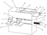
fig. 1 is a schematic structural view of the present invention;
FIG. 2 is a schematic view of the inner structure of the present invention;
fig. 3 is a schematic side view of the middle cabinet of the present invention;
FIG. 4 is a schematic side view of the interior of the present invention;
in the figure: 1. a chassis; 2. a frame; 3. supporting legs; 4. a semicircular block; 5. a first fixed block; 6. a first groove; 7. a first motor; 8. fixing the convex block; 9. a first shredder; 10. a second groove; 11. a second fixed block; 12. a second shredder; 13. moving the convex block; 14. a shaft sleeve; 15. rotating the rod; 16. a first fixing plate; 17. a first circular fixing plate; 18. a discharge plate; 19. a second motor; 20. a rectangular block; 21. a third groove; 22. a fourth groove; 23. a sliding plate; 24. a first push-pull rod; 25. pushing a plate; 26. a push rod; 27. a feeding port; 28. a second push-pull rod; 29. a second circular fixing plate; 30. a discharge port; 31. rotating the rod; 32. and a fifth groove.
Detailed Description
The technical solutions in the embodiments of the present invention will be described clearly and completely with reference to the accompanying drawings in the embodiments of the present invention, and it is obvious that the described embodiments are only some embodiments of the present invention, not all embodiments. Based on the embodiments in the present invention, all other embodiments obtained by a person skilled in the art without creative work belong to the protection scope of the present invention.
Examples
Referring to fig. 1-4, the present invention provides the following technical solutions: a crushing and sampling device for rock and ore detection comprises a machine case 1, wherein the top end of the machine case 1 is provided with a feeding port 27, the interior of the machine case 1 is fixed with a frame 2, four corners of the bottom end of the frame 2 are respectively fixed with a supporting leg 3, the top end of the frame 2 is fixed with a fixed convex block 8, the top end of the fixed convex block 8 is fixed with two first fixed blocks 5, the two first fixed blocks 5 are symmetrically attached to the inner wall of the machine case 1, the two first fixed blocks 5 are respectively provided with a first groove 6, the top end of the fixed convex block 8 is provided with a first motor 7, a first crusher 9 is arranged between the two first fixed blocks 5, the output end of the first motor 7 passes through the first crusher 9 and the two first grooves 6 to be attached to the inner wall of the machine case 1, the top end of the machine case 1 is provided with a movable convex block 13, the raised part of the movable convex block 13 is attached to the inner wall of the frame 2, the top end of the movable convex block 13 is fixed with two second fixed blocks 11, the two second fixed blocks 11 are symmetrically attached to the inner wall of the case 1, the two second fixed blocks 11 are provided with second grooves 10, the top end of a movable convex block 13 is provided with a second motor 19, the output end of the second motor 19 penetrates through the two second grooves 10 and a second crusher 12 to be attached to the inner wall of the case 1, the top end of a frame 2 is fixedly provided with a semicircular block 4, one side of the semicircular block 4 is attached to the inner wall of the case 1, one side of the movable convex block 13 is fixedly provided with a shaft sleeve 14, the inner wall of the shaft sleeve 14 is provided with a second circular fixed plate 29, one end of the second circular fixed plate 29 is fixedly provided with a rotating rod 15, one end of the rotating rod 15 penetrates through the frame 2 and the semicircular block 4 to be positioned outside the case 1, one end of the outer side of the rotating rod 15 is fixedly provided with a first fixed plate 16, one end of the first fixed plate 16 is provided with a rotating rod 31, and the bottom end of one side of the case 1 is provided with a discharge hole 30; when the adjustable crushing device is used, one ends of the movable convex block 13 and the fixed convex block 8 pass through the fourth groove 22 on the outer side of the case 1, the second motor 19 and the first motor 7 are installed, then the rotating rod 31 is rotated to adjust the rotating rod 15 in a spiral mode, and the second circular fixing plate 29 is rotatably connected with the shaft sleeve 14, so that the movable convex block 13 can move and adjust the crushing width when the rotating rod 31 rotates.
Specifically, as shown in fig. 1 and fig. 3, a third groove 21 and a fourth groove 22 are formed in one side of a chassis 1, a discharge plate 18 is installed at the bottom end of the inner side of the chassis 1, rectangular blocks 20 are symmetrically fixed on the inner wall of the chassis 1, the bottom ends of the rectangular blocks 20 are attached to the top ends of two first fixed blocks 5 and two second fixed blocks 11, a fifth groove 32 is formed in a position, close to the top end, of one side of the chassis 1, a sliding plate 23 is installed at the top end of the rectangular blocks 20, one end of the sliding plate 23 penetrates through the fifth groove 32, a first push-pull rod 24 is fixed at one end of the sliding plate 23, a push plate 25 is arranged at the top end of the sliding plate 23, a push rod 26 is fixed in the middle of one end of the push plate 25, one end of the push rod 26 penetrates through the chassis 1, a first circular fixed plate 17 is fixed at one end of the push rod 26, and a second push-pull rod 28 is fixed at one end of the first circular fixed plate 17; during the use, the pan feeding mouth 27 is opened to the first push-and-pull rod 24 of pulling, then pull catch bar 26 again with push pedal 25 and quick-witted case 1's inner wall laminating, just can start second motor 19 and first motor 7 after adjusting the width, put into pan feeding mouth 27 with the stone again after that, it drops on the top of sliding plate 23 to have some stones unavoidably at the pay-off in-process, at this moment reuse catch bar 26, impel the stone in pan feeding mouth 27, the stone after smashing can drop on ejection of compact board 18, ejection of compact board 18 is 45 installations, then can directly flow out from discharge gate 30.
The utility model discloses a theory of operation and use flow: when the feeding device is used, one end of the movable convex block 13 and one end of the fixed convex block 8 penetrate through the fourth groove 22 on the outer side of the case 1, the second motor 19 and the first motor 7 are installed, then the rotating rod 31 is rotated to adjust the rotating rod 15 in a spiral mode, the second round fixing plate 29 is rotatably connected with the shaft sleeve 14, the movable convex block 13 can move and adjust the crushing width along with the rotation of the rotating rod 31, then the first push-pull rod 24 is pulled to open the feeding port 27, then the push rod 26 is pulled to attach the push plate 25 to the inner wall of the case 1, the second motor 19 and the first motor 7 can be started after the width is adjusted, then stones are put into the feeding port 27, some stones can hardly fall onto the top end of the sliding plate 23 in the feeding process, at the moment, the push rod 26 is used again to push the crushed stones into the feeding port 27 to fall onto the discharge plate 18, the discharge plate 18 is installed at an angle of 45 degrees, and then the stones can directly flow out from the discharge port 30.
In the description of the present invention, it is to be understood that the terms "center", "longitudinal", "lateral", "length", "width", "thickness", "upper", "lower", "front", "rear", "left", "right", "vertical", "horizontal", "top", "bottom", "inner", "outer", "clockwise", "counterclockwise", "axial", "radial", "circumferential", and the like, indicate the orientation or positional relationship indicated based on the drawings, and are only for convenience of description and simplicity of description, and do not indicate or imply that the device or element referred to must have a particular orientation, be constructed and operated in a particular orientation, and therefore, should not be construed as limiting the present invention.
In the present invention, unless otherwise explicitly specified or limited, the terms "disposed," "mounted," "connected," "secured," and the like are to be construed broadly, e.g., as either a fixed connection, a detachable connection, or an integral part; they may be mechanically coupled, directly coupled, indirectly coupled through intervening media, and may be interconnected or interconnected between two elements. The specific meaning of the above terms in the present invention can be understood according to specific situations by those of ordinary skill in the art.
Furthermore, the terms "first", "second" and "first" are used for descriptive purposes only and are not to be construed as indicating or implying relative importance or implicitly indicating the number of technical features indicated. Thus, a feature defined as "first" or "second" may explicitly or implicitly include one or more of that feature. In the description of the present invention, "a plurality" means two or more unless specifically limited otherwise.
It is noted that in the present disclosure, unless otherwise explicitly specified or limited, a first feature "on" or "under" a second feature may be directly contacting the first and second features or indirectly contacting the first and second features through an intermediate. Also, a first feature "on," "over," and "above" a second feature may be directly or diagonally above the second feature, or may simply indicate that the first feature is at a higher level than the second feature. A first feature being "under," "below," and "beneath" a second feature may be directly under or obliquely under the first feature, or may simply mean that the first feature is at a lesser elevation than the second feature.
Finally, it should be noted that: although the present invention has been described in detail with reference to the foregoing embodiments, it will be apparent to those skilled in the art that modifications may be made to the embodiments described in the foregoing embodiments, or equivalents may be substituted for elements thereof. Any modification, equivalent replacement, or improvement made within the spirit and principle of the present invention should be included in the protection scope of the present invention.
Claims (5)
1. The utility model provides a rock and ore deposit detects with smashing sampler, includes quick-witted case (1), its characterized in that: the top end of the case (1) is provided with a feeding port (27), a frame (2) is fixed inside the case (1), support legs (3) are fixed at four corners of the bottom end of the frame (2), a fixed convex block (8) is fixed at the top end of the frame (2), two first fixed blocks (5) are fixed at the top end of the fixed convex block (8), the two first fixed blocks (5) are symmetrically attached to the inner wall of the case (1), first grooves (6) are formed in the two first fixed blocks (5), a first motor (7) is installed at the top end of the fixed convex block (8), a first pulverizer (9) is installed between the two first fixed blocks (5), the output end of the first motor (7) penetrates through the first pulverizer (9) and the two first grooves (6) to be attached to the inner wall of the case (1), a movable convex block (13) is installed at the top end of the case (1), the protruding part of the movable convex block (13) is attached to the inner wall of the frame (2), the top end of the movable convex block (13) is provided with a second groove (11), and the second groove (11) is installed at the top end of the second groove (11), the output end of the second motor (19) passes through two second grooves (10) and the inner wall laminating of the second crusher (12) and the case (1), the top end of the frame (2) is fixed with a semicircular block (4), one side of the semicircular block (4) is laminated with the inner wall of the case (1), one side of the movable convex block (13) is fixed with an axle sleeve (14), a second circular fixing plate (29) is installed on the inner wall of the axle sleeve (14), one end of the second circular fixing plate (29) is fixed with a rotating rod (15), one end of the rotating rod (15) passes through the outer sides of the frame (2) and the semicircular block (4) in the case (1), one end of the outer side of the rotating rod (15) is fixed with a first fixing plate (16), one end of the first fixing plate (16) is provided with a rotating rod (31), and the bottom end of one side of the case (1) is provided with a discharge port (30).
2. The crushing sampler for rock ore detection according to claim 1, characterized in that: a third groove (21) and a fourth groove (22) are formed in one side of the case (1), and a discharge plate (18) is mounted at the bottom end of the inner side of the case (1).
3. The crushing sampler for rock ore detection according to claim 1, characterized in that: the inner wall of the case (1) is symmetrically fixed with rectangular blocks (20), and the bottom ends of the rectangular blocks (20) are attached to the top ends of the two first fixed blocks (5) and the top ends of the two second fixed blocks (11).
4. The crushing sampler for rock ore detection according to claim 1, characterized in that: a fifth groove (32) is formed in a position, close to the top end, of one side of the case (1), a sliding plate (23) is installed at the top end of the rectangular block (20), one end of the sliding plate (23) penetrates through the fifth groove (32), and a first push-pull rod (24) is fixed to one end of the sliding plate (23).
5. The crushing sampler for rock ore detection according to claim 4, characterized in that: the top end of the sliding plate (23) is provided with a push plate (25), the middle of one end of the push plate (25) is fixed with a push rod (26), one end of the push rod (26) penetrates through the case (1), one end of the push rod (26) is fixed with a first circular fixing plate (17), and one end of the first circular fixing plate (17) is fixed with a second push-pull rod (28).
Priority Applications (1)
| Application Number | Priority Date | Filing Date | Title |
|---|---|---|---|
| CN202222097393.5U CN218156916U (en) | 2022-08-10 | 2022-08-10 | Rock and ore deposit detects with smashing sampler |
Applications Claiming Priority (1)
| Application Number | Priority Date | Filing Date | Title |
|---|---|---|---|
| CN202222097393.5U CN218156916U (en) | 2022-08-10 | 2022-08-10 | Rock and ore deposit detects with smashing sampler |
Publications (1)
| Publication Number | Publication Date |
|---|---|
| CN218156916U true CN218156916U (en) | 2022-12-27 |
Family
ID=84600200
Family Applications (1)
| Application Number | Title | Priority Date | Filing Date |
|---|---|---|---|
| CN202222097393.5U Active CN218156916U (en) | 2022-08-10 | 2022-08-10 | Rock and ore deposit detects with smashing sampler |
Country Status (1)
| Country | Link |
|---|---|
| CN (1) | CN218156916U (en) |
Cited By (1)
| Publication number | Priority date | Publication date | Assignee | Title |
|---|---|---|---|---|
| CN116213025A (en) * | 2023-05-05 | 2023-06-06 | 山东省地质矿产勘查开发局第一地质大队(山东省第一地质矿产勘查院) | Breaker for mineral exploration ore analysis |
-
2022
- 2022-08-10 CN CN202222097393.5U patent/CN218156916U/en active Active
Cited By (1)
| Publication number | Priority date | Publication date | Assignee | Title |
|---|---|---|---|---|
| CN116213025A (en) * | 2023-05-05 | 2023-06-06 | 山东省地质矿产勘查开发局第一地质大队(山东省第一地质矿产勘查院) | Breaker for mineral exploration ore analysis |
Similar Documents
| Publication | Publication Date | Title |
|---|---|---|
| CN218156916U (en) | Rock and ore deposit detects with smashing sampler | |
| CN108855613A (en) | A kind of ore magnetic separator | |
| CN110180637B (en) | Sand making machine capable of circulating operation | |
| CN111804393A (en) | Automatic sand making machine capable of circularly crushing | |
| CN209715338U (en) | A kind of bombardment formula ore pulverizer | |
| CN209362611U (en) | A kind of ball mill with impurity removal function | |
| CN209049454U (en) | A kind of crusher based on building material production preparation | |
| CN214974367U (en) | Dry separation equipment for tailing slag | |
| CN212468323U (en) | Vertical grinding and crushing device for environment-friendly pulverized coal | |
| CN210613893U (en) | Efficient energy-saving rod mill for mineral processing technology | |
| CN219292037U (en) | Automatic impurity screening device of pulverizer | |
| CN214600310U (en) | Special sand making separator for mine | |
| CN217120517U (en) | Pulverizer for preparing fine-particle niobium oxide | |
| CN218250744U (en) | Anti-blocking device of crushed stone crusher | |
| CN217774356U (en) | Iron scale recovery plant | |
| CN218654736U (en) | Porcelain pug ball mill for celadon production | |
| CN218250573U (en) | Ball mill of foundry goods processing usefulness | |
| CN219560484U (en) | Dry powder mortar sand material separator | |
| CN217527757U (en) | Vertical mill for natural flake graphite ore dressing | |
| CN220126457U (en) | Pulverizer convenient for collecting and pulverizing ginger | |
| CN220215760U (en) | Sand-stone separation powder separator with uniform bulk material | |
| CN216207788U (en) | Rock and ore deposit detects with smashing sampling device | |
| CN219788930U (en) | Raw material crusher for producing packaging mold film-wetting adhesive tape | |
| CN214347726U (en) | Particle separation device for rare earth | |
| CN213315210U (en) | Energy-efficient building construction device |
Legal Events
| Date | Code | Title | Description |
|---|---|---|---|
| GR01 | Patent grant | ||
| GR01 | Patent grant |