CN218152705U - Drain pipe fixing device for building outer wall - Google Patents
Drain pipe fixing device for building outer wall Download PDFInfo
- Publication number
- CN218152705U CN218152705U CN202221083241.3U CN202221083241U CN218152705U CN 218152705 U CN218152705 U CN 218152705U CN 202221083241 U CN202221083241 U CN 202221083241U CN 218152705 U CN218152705 U CN 218152705U
- Authority
- CN
- China
- Prior art keywords
- pipeline
- wall
- joint
- fixed plate
- drain pipe
- Prior art date
- Legal status (The legal status is an assumption and is not a legal conclusion. Google has not performed a legal analysis and makes no representation as to the accuracy of the status listed.)
- Active
Links
Images


Landscapes
- Sink And Installation For Waste Water (AREA)
Abstract
The utility model discloses a drain pipe fixing device for building outer wall, the pipeline comprises a pipeline, the equal joint in surface of pipeline upper end and lower extreme has the position sleeve, the equal integrated into one piece in both sides of position sleeve has the spacer, the rear side joint at pipeline middle part has the fixed plate, and the front of fixed plate has the joint board and lies in the surface joint of pipeline, and the arc wall has all been seted up with the inboard of fixed plate to the joint board, and the inner wall of arc wall bonds and has sealed the pad, the surperficial joint of pipeline between two arc walls and with sealed pad in close contact with. The utility model discloses an it can be fixed fast to the both ends of pipeline to increase the position sleeve on the surface of pipeline, and the middle part is connected with the joint board through the fixed plate in addition, can strengthen the whole fastness after the installation, and this structure can carry out the sectional type to the surface of pipeline fixed, and not only the firm degree of installation is high, wholly is difficult for producing moreover on the wall body to rock, and quick assembly disassembly can be accomplished to the use tools when demolising at the later stage.
Description
Technical Field
The utility model relates to a building technical field specifically is a drain pipe fixing device for building outer wall.
Background
At present house drainage system adopts centralized drainage mode to carry out the drainage more, the rainwater is discharged through drainage pipe after the roof assembles promptly, just need carry out reliable fixed to the drain pipe in order to improve drainage system's stability ability and drainage system's security performance, the pipe fixing clip that falls of the emission rainwater on civilian and the industrial building outer wall generally adopts cement sealed fixed, it is inconvenient to damage the back dismouting in the pipeline appears, and after first installation, the fastener can produce after using for a long time loosely, the fastener drops in strong wind weather, the pipeline drops and can cause the damage, the potential safety hazard has still been increased.
SUMMERY OF THE UTILITY MODEL
An object of the utility model is to provide a drain pipe fixing device for building outer wall possesses the installation firm, and the fastener can produce not hard up after long-time the use has been solved to the advantage of the dismouting of being convenient for, and the fastener drops in strong wind weather, and the pipeline drops and can cause the problem of damage.
In order to achieve the above object, the utility model provides a following technical scheme: the utility model provides a drain pipe fixing device for building outer wall, includes the pipeline, the equal joint in surface of pipeline upper end and lower extreme has the position sleeve, the equal integrated into one piece in both sides of position sleeve has the spacer, the rear side joint at pipeline middle part has the fixed plate, the front of fixed plate and the surface joint that is located the pipeline have the joint board, the arc wall has all been seted up with the inboard of fixed plate to the joint board, and the inner wall of arc wall bonds and has sealed the pad, the surface joint of pipeline between two arc walls and with sealed the pad in close contact with, the equal fixed mounting in upper and lower both ends of fixed plate both sides has the locating piece, the front of locating piece is run through and is provided with the second bolt, the rear end of second bolt extends to the rear side of locating piece.
Preferably, the upper side and the lower side of the front surface of the fixing plate are both provided with clamping grooves, the clamping blocks are clamped in the clamping grooves, and the front surfaces of the clamping blocks and the back surfaces of the clamping plates are fixedly installed.
Preferably, the surface of the positioning plate is provided with a positioning hole, the front side of the positioning plate is provided with a first bolt, and the rear end of the first bolt penetrates through the positioning hole and extends to the rear side of the positioning plate.
Preferably, the inside of position sleeve is the indent type setting, the surperficial joint of pipeline is provided with the rubber pad in the inside of position sleeve and at the laminating of surface, the surface of rubber pad bonds with the inner wall of position sleeve.
Preferably, the width of the rubber pad is larger than that of the positioning sleeve, and the rubber pad is arranged in a semi-arc shape.
Compared with the prior art, the beneficial effects of the utility model are as follows:
1. the utility model discloses an it can be fixed fast to the both ends of pipeline to increase the position sleeve on the surface of pipeline, and the middle part is connected with the joint board through the fixed plate, can strengthen the whole fastness after the installation, this structure can carry out the sectional type to the surface of pipeline and fix, not only install firm degree high, wholly difficult production on the wall body rocks in addition, quick assembly disassembly can be accomplished to the use tools when demolising at the later stage, it can produce not hard up after long-time the use to have solved the fastener simultaneously, the fastener drops in strong wind weather, the pipeline drops and can cause the problem of damage.
2. The utility model discloses an increase the rubber pad in the inside of position sleeve, can protect the surface of pipeline, prevent that the tight dynamics of clamp from too big causing surface wear, the inside sealed pad of arc wall is protected the surface of pipeline in step moreover, can also prevent that the junction from producing the clearance, increases the fastness after the installation.
Drawings
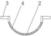
FIG. 1 is a schematic structural view of the present invention;
FIG. 2 is a top view of the positioning sleeve structure of the present invention;
FIG. 3 is a left side sectional view of the fixing plate structure of the present invention;
fig. 4 is a top view of the fixing plate and the clamping plate cooperating structure of the present invention.
In the figure: 1. a pipeline; 2. a positioning sleeve; 3. positioning plates; 4. a rubber pad; 5. a fixing plate; 6. a clamping plate; 7. a gasket; 8. positioning blocks; 9. a first bolt; 10. a second bolt; 11. a card slot; 12. and (7) clamping blocks.
Detailed Description
The technical solutions in the embodiments of the present invention will be described clearly and completely with reference to the accompanying drawings in the embodiments of the present invention, and it is obvious that the described embodiments are only some embodiments of the present invention, not all embodiments. Based on the embodiments in the present invention, all other embodiments obtained by a person skilled in the art without creative efforts all belong to the protection scope of the present invention.
Referring to fig. 1-4, a drain pipe fixing device for an outer wall of a building comprises a pipeline 1, positioning sleeves 2 are clamped on the surfaces of the upper end and the lower end of the pipeline 1, the positioning sleeves 2 are arranged in a concave manner, a rubber pad 4 is clamped inside the positioning sleeves 2 on the surface of the pipeline 1 and is attached to the surface of the pipeline, the outer surface of the rubber pad 4 is adhered to the inner wall of the positioning sleeves 2, the width of the rubber pad 4 is larger than that of the positioning sleeves 2, the rubber pad 4 is arranged in a semi-arc manner, the surface of the pipeline 1 can be protected by adding the rubber pad 4 inside the positioning sleeves 2, surface abrasion caused by overlarge clamping force is prevented, a sealing pad 7 inside an arc-shaped groove synchronously protects the surface of the pipeline 1, gaps at joints can be prevented, firmness after installation is improved, positioning sheets 3 are integrally formed on two sides of the positioning sleeves 2, positioning holes are formed on the surface of the positioning sheets 3, the front side of the positioning plate 3 is provided with a first bolt 9, the rear end of the first bolt 9 penetrates through the positioning hole and extends to the rear side of the positioning plate 3, the rear side of the middle part of the pipeline 1 is clamped with a fixing plate 5, the upper side and the lower side of the front of the fixing plate 5 are both provided with clamping grooves 11, the inner parts of the clamping grooves 11 are clamped with clamping blocks 12, the front of each clamping block 12 is fixedly installed with the back of the clamping plate 6, the front of the fixing plate 5 is clamped with the clamping plate 6 on the outer surface of the pipeline 1, the clamping plate 6 and the inner sides of the fixing plate 5 are both provided with arc-shaped grooves, the inner walls of the arc-shaped grooves are bonded with sealing gaskets 7, the surface of the pipeline 1 is clamped between the two arc-shaped grooves and is tightly contacted with the sealing gaskets 7, the upper end and the lower end of the two sides of the fixing plate 5 are both fixedly provided with positioning blocks 8, the front of the positioning blocks 8 is provided with a second bolt 10 in a penetrating manner, and the rear end of the second bolt 10 extends to the rear side of the positioning blocks 8, can be to pipeline 1's both ends quick fixation through increase position sleeve 2 in pipeline 1's surface, and the middle part is connected with joint board 6 through fixed plate 5, can strengthen the whole fastness after the installation, this structure can carry out the sectional type to pipeline 1's surface and fix, not only the firm degree of installation is high, and whole difficult production is rocked on the wall body, quick assembly disassembly can be accomplished to use tools when demolising in the later stage, it can produce not hard up after long-time the use to have solved the fastener simultaneously, the fastener drops in strong wind weather, the pipeline drops and can cause the problem of damage.
During the use, can be to the both ends of pipeline 1 quick fixation through increase position sleeve 2 on the surface of pipeline 1, and pass locating hole and wall body high-speed joint with first bolt 9, then fix fixed plate 5 through second bolt 10 to locating piece 8 in the suitable position of wall body, the one end that makes pipeline 1 is located the inside of fixed plate 5, then block 12 card at the 6 backs of joint board inside draw-in groove 11, pass joint board 6 with external screw and be connected with fixed plate 5, can strengthen the whole fastness after the installation, this structure can carry out the sectional type to pipeline 1's surface and fix, not only the firm degree of installation is high, and whole difficult production is rocked on the wall body, quick assembly disassembly can be accomplished to the use of instrument when demolising in the later stage.
Although embodiments of the present invention have been shown and described, it will be appreciated by those skilled in the art that changes, modifications, substitutions and alterations can be made in these embodiments without departing from the principles and spirit of the invention, the scope of which is defined in the appended claims and their equivalents.
Claims (5)
1. The utility model provides a drain pipe fixing device for building outer wall, includes pipeline (1), its characterized in that: the equal joint in surface of pipeline (1) upper end and lower extreme has position sleeve (2), the equal integrated into one piece in both sides of position sleeve (2) has spacer (3), the rear side joint at pipeline (1) middle part has fixed plate (5), the front of fixed plate (5) and the surface joint that is located pipeline (1) have joint board (6), the arc wall has all been seted up with the inboard of fixed plate (5) to joint board (6), and the inner wall of arc wall bonds and has sealed pad (7), the surperficial joint of pipeline (1) between two arc walls and with sealed pad (7) in close contact with, the equal fixed mounting in upper and lower both ends of fixed plate (5) both sides has locating piece (8), the front of locating piece (8) is run through and is provided with second bolt (10), the rear end of second bolt (10) extends to the rear side of locating piece (8).
2. The drain pipe fixing device for the outer wall of the building according to claim 1, wherein: draw-in groove (11) have all been seted up to the positive upper and lower both sides of fixed plate (5), the inside joint of draw-in groove (11) has fixture block (12), the front of fixture block (12) and the back fixed mounting of joint board (6).
3. The drain pipe fixing device for the outer wall of the building according to claim 1, wherein: the positioning structure is characterized in that positioning holes are formed in the surface of the positioning sheet (3), first bolts (9) are arranged on the front side of the positioning sheet (3), and the rear ends of the first bolts (9) penetrate through the positioning holes and extend to the rear side of the positioning sheet (3).
4. The drain pipe fixing device for the outer wall of the building according to claim 1, wherein: the inside of position sleeve (2) is the concave type setting, the surperficial joint of pipeline (1) is provided with rubber pad (4) in the inside of position sleeve (2) and at the laminating of surface, the surface of rubber pad (4) bonds with the inner wall of position sleeve (2).
5. The drain pipe fixing device for the outer wall of the building according to claim 4, wherein: the width of the rubber pad (4) is larger than that of the positioning sleeve (2), and the rubber pad (4) is arranged in a semi-arc shape.
Priority Applications (1)
| Application Number | Priority Date | Filing Date | Title |
|---|---|---|---|
| CN202221083241.3U CN218152705U (en) | 2022-05-08 | 2022-05-08 | Drain pipe fixing device for building outer wall |
Applications Claiming Priority (1)
| Application Number | Priority Date | Filing Date | Title |
|---|---|---|---|
| CN202221083241.3U CN218152705U (en) | 2022-05-08 | 2022-05-08 | Drain pipe fixing device for building outer wall |
Publications (1)
| Publication Number | Publication Date |
|---|---|
| CN218152705U true CN218152705U (en) | 2022-12-27 |
Family
ID=84571903
Family Applications (1)
| Application Number | Title | Priority Date | Filing Date |
|---|---|---|---|
| CN202221083241.3U Active CN218152705U (en) | 2022-05-08 | 2022-05-08 | Drain pipe fixing device for building outer wall |
Country Status (1)
| Country | Link |
|---|---|
| CN (1) | CN218152705U (en) |
-
2022
- 2022-05-08 CN CN202221083241.3U patent/CN218152705U/en active Active
Similar Documents
| Publication | Publication Date | Title |
|---|---|---|
| CN107130760B (en) | Combined wallboard convenient to install | |
| CN218152705U (en) | Drain pipe fixing device for building outer wall | |
| CN210562876U (en) | Effective waterproof glass curtain wall | |
| CN205370598U (en) | Section of jurisdiction sealing strip | |
| CN218235131U (en) | Novel shield constructs section of jurisdiction convenient to installation | |
| CN211925073U (en) | Slip casting union coupling device for pile foundation construction | |
| CN201526097U (en) | Assembly and installation structure of fire-proof plate | |
| CN210127581U (en) | Greenhouse gutter drainage structure | |
| CN201762896U (en) | Profiling steel plate clamping structure for building | |
| CN210372455U (en) | Groove type wedge surface interface | |
| CN212612063U (en) | Novel road and bridge acoustic celotex board is fixed device | |
| CN211127667U (en) | L foot support suitable for trapezoidal various steel tile | |
| CN219840276U (en) | Color steel tile convenient to splice | |
| CN220644662U (en) | Sealing device for concrete of assembled sewage plant | |
| CN214366909U (en) | Sealed corrosion-resistant SA type petrochemical industry process pump | |
| CN220789867U (en) | Basement waterproof construction | |
| CN216767166U (en) | Door and window frame splicing mechanism | |
| CN220915230U (en) | Double-glass assembly clamp with high reliability of connecting assembly | |
| CN217208037U (en) | Double-rubber-ring steel bell and spigot pipe for long-distance construction | |
| CN216923581U (en) | Wind power hydraulic pipe assembly | |
| CN210978096U (en) | Connecting and sealing device for installation of corrugated plate | |
| CN219260892U (en) | Safety protection structure applied to reservoir dykes and dams | |
| CN219569370U (en) | Fixing device of metal roofing structure | |
| CN214994073U (en) | Double-deck waterproof concrete wall of basement | |
| CN214365787U (en) | Door with sealing structure |
Legal Events
| Date | Code | Title | Description |
|---|---|---|---|
| GR01 | Patent grant | ||
| GR01 | Patent grant |