CN218141094U - New energy automobile fills protector for electric pile - Google Patents
New energy automobile fills protector for electric pile Download PDFInfo
- Publication number
- CN218141094U CN218141094U CN202222019202.3U CN202222019202U CN218141094U CN 218141094 U CN218141094 U CN 218141094U CN 202222019202 U CN202222019202 U CN 202222019202U CN 218141094 U CN218141094 U CN 218141094U
- Authority
- CN
- China
- Prior art keywords
- rigid coupling
- new energy
- guide frame
- energy automobile
- stake
- Prior art date
- Legal status (The legal status is an assumption and is not a legal conclusion. Google has not performed a legal analysis and makes no representation as to the accuracy of the status listed.)
- Active
Links
Images


Classifications
-
- Y—GENERAL TAGGING OF NEW TECHNOLOGICAL DEVELOPMENTS; GENERAL TAGGING OF CROSS-SECTIONAL TECHNOLOGIES SPANNING OVER SEVERAL SECTIONS OF THE IPC; TECHNICAL SUBJECTS COVERED BY FORMER USPC CROSS-REFERENCE ART COLLECTIONS [XRACs] AND DIGESTS
- Y02—TECHNOLOGIES OR APPLICATIONS FOR MITIGATION OR ADAPTATION AGAINST CLIMATE CHANGE
- Y02T—CLIMATE CHANGE MITIGATION TECHNOLOGIES RELATED TO TRANSPORTATION
- Y02T10/00—Road transport of goods or passengers
- Y02T10/60—Other road transportation technologies with climate change mitigation effect
- Y02T10/70—Energy storage systems for electromobility, e.g. batteries
-
- Y—GENERAL TAGGING OF NEW TECHNOLOGICAL DEVELOPMENTS; GENERAL TAGGING OF CROSS-SECTIONAL TECHNOLOGIES SPANNING OVER SEVERAL SECTIONS OF THE IPC; TECHNICAL SUBJECTS COVERED BY FORMER USPC CROSS-REFERENCE ART COLLECTIONS [XRACs] AND DIGESTS
- Y02—TECHNOLOGIES OR APPLICATIONS FOR MITIGATION OR ADAPTATION AGAINST CLIMATE CHANGE
- Y02T—CLIMATE CHANGE MITIGATION TECHNOLOGIES RELATED TO TRANSPORTATION
- Y02T10/00—Road transport of goods or passengers
- Y02T10/60—Other road transportation technologies with climate change mitigation effect
- Y02T10/7072—Electromobility specific charging systems or methods for batteries, ultracapacitors, supercapacitors or double-layer capacitors
-
- Y—GENERAL TAGGING OF NEW TECHNOLOGICAL DEVELOPMENTS; GENERAL TAGGING OF CROSS-SECTIONAL TECHNOLOGIES SPANNING OVER SEVERAL SECTIONS OF THE IPC; TECHNICAL SUBJECTS COVERED BY FORMER USPC CROSS-REFERENCE ART COLLECTIONS [XRACs] AND DIGESTS
- Y02—TECHNOLOGIES OR APPLICATIONS FOR MITIGATION OR ADAPTATION AGAINST CLIMATE CHANGE
- Y02T—CLIMATE CHANGE MITIGATION TECHNOLOGIES RELATED TO TRANSPORTATION
- Y02T90/00—Enabling technologies or technologies with a potential or indirect contribution to GHG emissions mitigation
- Y02T90/10—Technologies relating to charging of electric vehicles
- Y02T90/12—Electric charging stations
Abstract
The utility model discloses a new energy automobile fills protection device for electric pile belongs to the new energy automobile field, comprising a base plate, the top surface rigid coupling of bottom plate has the stake, the rigid coupling has the rifle that charges on the output of stake, and the top surface rigid coupling of stake has the support, the rigid coupling has solar cell panel between the inside wall of support, and the top surface both sides of support rigid coupling respectively have the guide frame, slide respectively in the guide frame and cup jointed smooth button one and smooth button two, equal rigid coupling has the baffle on the terminal surface of smooth button one and smooth button two. The protection device can avoid the damage of the solar cell panel, the solar cell panel of the automobile charging pile is not required to be replaced, the investment of cost is reduced, the low-carbon environment-friendly effect is improved, the vertical pile of the automobile charging pile can be fully protected, the automobile charging pile is not prone to damage, the service life of the automobile charging pile is prolonged, and the electric leakage hidden danger is reduced.
Description
Technical Field
The utility model relates to a new energy automobile field specifically is a new energy automobile fills electric pile and uses protector.
Background
The new energy automobile charging pile has the function similar to that of an oiling machine in a gas station, can be fixed on the ground, can also be installed in parking lots or charging stations of public buildings and residential districts, can charge electric automobiles of various models according to different voltage grades, and is provided with charging snatches at the output end for charging the electric automobiles;
general car on the market fills electric pile and sets up in roadside or parking stall rear more, make the car fill electric pile easily by the vehicle collision, thereby make the car fill electric pile fragile, the life of the electric pile is filled not only to the car has been reduced, still easily produce the electric leakage hidden danger, and the solar panel that general car fills electric pile is many fixed towards the sky, make solar cell panel easily receive rainwater erosion, thereby make solar cell panel fragile, not only the input of cost has been increased, low carbon environmental protection effect has still been reduced, the problem of device defect has been brought, for this, we provide a new energy automobile fills electric pile and uses protector.
SUMMERY OF THE UTILITY MODEL
An object of the utility model is to provide a new energy automobile fills electric pile and uses protector, it sets up in roadside or parking stall rear more to fill electric pile with general car that proposes in solving above-mentioned background art, it is easy by the vehicle collision to make the car fill electric pile fragile, not only reduced the life that the car fills electric pile, still easily produce the electric leakage hidden danger, and the many fixed orientation sky of solar panel that general car filled electric pile, make solar panel easily receive the rainwater erosion, thereby make solar panel fragile, not only the input of cost has been increased, low carbon environmental protection effect has still been reduced, the problem of device defect has been brought.
In order to achieve the above purpose, the utility model provides a following technical scheme: the utility model provides a new energy automobile fills electric pile and uses protector, includes the bottom plate, the top surface rigid coupling of bottom plate has the stake, the rigid coupling has the rifle that charges on the output of stake, and the top surface rigid coupling of stake has the support, the rigid coupling has solar cell panel between the inside wall of support, and the top surface both sides of support rigid coupling have the guide frame respectively, slide respectively in the guide frame and cup jointed smooth button one and smooth button two, equal rigid coupling has the baffle on the terminal surface of smooth button one and smooth button two, and the other end of smooth button two rotates and cup joints the slider, pneumatic putter is installed to the bottom surface of slider, pneumatic putter's bottom surface fixed cover has cup jointed the fixed plate.
Preferably, the guide frame is symmetrically arranged about a bisector of the support, the guide frame is L-shaped, the sliding block is slidably connected with the side wall of the guide frame, and the fixed plate is fixedly connected with the side wall of the bottom end of the guide frame.
Preferably, the inboard slide of guide frame is the setting of L type, and the right angle corner of slide is the arc setting.
Preferably, the rigid coupling has the concrete to keep off the stake on the lateral wall of bottom plate, the fixed bottom cover that the stake was kept off to the concrete has connect the embedded muscle, the grout hole has been seted up in the concrete fender stake between the embedded muscle, the cavity has been seted up to the front end that the stake is kept off to the concrete, the rigid coupling has stereoplasm rubber one and stereoplasm rubber two respectively on the inner wall at cavity both ends, the rigid coupling has between stereoplasm rubber one and the stereoplasm rubber two to block the frame, it has the telescopic link to block the rigid coupling between the lateral wall of frame and stereoplasm rubber one, the external surface fixing of telescopic link has cup jointed the spring.
Preferably, the blocking frame is arranged in a right-angled triangle shape, and two ends of the spring are fixedly connected with the blocking frame and the side wall of the first hard rubber respectively.
Preferably, the bottom of blocking the frame extends to outside the cavity, pre-buried muscle and grout hole are provided with the multiunit respectively, and multiunit pre-buried muscle and grout hole parallel arrangement.
Compared with the prior art, the beneficial effects of the utility model are that:
the protective device drives the sliding block on the protective device to descend through the pneumatic push rod, so that the sliding block drives the sliding button II in the guide frame to descend, the sliding button II drives the sliding button I to move along a slide way in the guide frame through the baffle, when the sliding button I moves to the right-angle corner of the slide way, due to the arc-shaped arrangement of the right-angle corner of the slide way, the resultant force direction of the sliding button I is horizontally rightward, the sliding button I is changed from vertical movement to horizontal movement, the bottom end of the baffle is driven to turn, until the sliding button II moves to the right-angle corner of the slide way, the baffle is completely horizontal, the baffle covers right above the solar cell panel at the moment, rain or snow falling onto the solar cell panel is avoided, the solar cell panel of an automobile charging pile is prevented from being damaged, the solar cell panel of the automobile charging pile does not need to be replaced, cost investment is reduced, and the low-carbon and environment-friendly effects are improved;
this protector blocks new energy automobile's the gos forward through the front end that the concrete kept off the stake, make new energy automobile's impact kinetic energy transmit to on the stereoplasm rubber two, make the stereoplasm rubber two preliminary absorption impact kinetic energy, remaining impact kinetic energy can be transmitted to on blocking the frame by stereoplasm rubber two, make and block the frame and strike some impact kinetic energy direction to the ground in, and through spring and the storage impact kinetic energy of stereoplasm rubber one, reach the mesh of fully alleviating impact kinetic energy, thereby the stake of stake is filled to the fully protected car, make the car fill electric pile not fragile, the life that not only improves the car fill electric pile, the electric leakage hidden danger has still been reduced.
Drawings
FIG. 1 is a schematic view of the overall structure of the present invention;
FIG. 2 is an enlarged view of a portion A of FIG. 1;
FIG. 3 is an enlarged view of the portion B of FIG. 1;
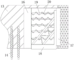
fig. 4 is a sectional view of the concrete retaining pile structure of the present invention.
In the figure: 1. a base plate; 2. erecting a pile; 3. a charging gun; 4. a support; 5. a solar panel; 6. a guide frame; 7. a first slide button; 8. a second sliding button; 9. a baffle plate; 10. a slider; 11. a pneumatic push rod; 12. a fixing plate; 13. blocking piles by concrete; 14. pre-burying ribs; 15. grouting holes; 16. hard rubber I; 17. hard rubber II; 18. a blocking frame; 19. a telescopic rod; 20. a spring.
Detailed Description
The technical solutions in the embodiments of the present invention will be described clearly and completely with reference to the drawings in the embodiments of the present invention, and it is obvious that the described embodiments are only some embodiments of the present invention, not all embodiments. Based on the embodiments in the present invention, all other embodiments obtained by a person skilled in the art without creative work belong to the protection scope of the present invention.
Example 1:
referring to fig. 1-2, the present invention provides a technical solution: the utility model provides a new energy automobile fills protection device for electric pile, comprising a base plate 1, the top surface rigid coupling of bottom plate 1 has stump 2, the rigid coupling has charging gun 3 on the output of stump 2, and the top surface rigid coupling of stump 2 has support 4, the rigid coupling has solar cell panel 5 between the inside wall of support 4, and the top surface both sides of support 4 rigid coupling have guide frame 6 respectively, slide button 7 and slide button two 8 have been cup jointed in the guide frame 6 respectively to the slip, equal rigid coupling has baffle 9 on the terminal surface of slide button 7 and slide button two 8, and slide button two 8's the other end rotates and has cup jointed slider 10, pneumatic push rod 11 is installed to the bottom surface of slider 10, pneumatic push rod 11's bottom surface fixed cover has been cup jointed fixed plate 12, guide frame 6 sets up about the bisector symmetry of support 4, and guide frame 6 is the L type setting, slider 10 and guide frame 6's lateral wall sliding connection, fixed plate 12 and guide frame 6's bottom lateral wall rigid coupling of corner, the inboard of guide frame 6 is the L type setting, and the right angle of slide is the arc setting.
Concretely, when protecting car and fill electric pile's solar cell panel 5, drive slider 10 on it through pneumatic push rod 11 and descend, thereby make slider 10 drive the decline of slide button two 8 in the guide frame 6, make slide button two 8 drive slide button 7 through baffle 9 and move along the slide in the guide frame 6, when slide button 7 removes the right angle corner to the slide, because slide right angle corner's circular arc type setting, make the resultant force direction level of slide button one 7 right, thereby make slide button one 7 become horizontal migration by vertical removal, thereby drive the bottom of baffle 9 and turn to, when moving to the right angle corner of slide button two 8, baffle 9 will be complete level, baffle 9 covers directly over solar cell panel 5 this moment, thereby avoid the rain or the snow that descend to fall on solar cell panel 5, the solar cell panel 5 of car and having avoided car to fill electric pile damages, need not to change car and fill electric pile's solar cell panel 5, the input of low carbon cost has not only been reduced, the effect of low carbon environmental protection has still been improved.
Example 2:
referring to fig. 1 and fig. 3-4, the present invention provides a technical solution: the utility model provides a new energy automobile fills protector for electric pile, the rigid coupling has concrete fender pile 13 on the lateral wall of bottom plate 1, the fixed cover in bottom of concrete fender pile 13 has pre-buried muscle 14, grout hole 15 has been seted up in the concrete fender pile 13 between the pre-buried muscle 14, the cavity has been seted up to the front end of concrete fender pile 13, the rigid coupling has first ebonite and second ebonite 17 on the inner wall at cavity both ends respectively, the rigid coupling has barrier frame 18 between ebonite 16 and second ebonite 17, the rigid coupling has telescopic link 19 between barrier frame 18 and the lateral wall of ebonite 16, spring 20 has been cup jointed to the external surface mounting of telescopic link 19, barrier frame 18 is the triangle-shaped setting, the both ends of spring 20 respectively with barrier frame 18 and the lateral wall rigid ebonite 16 rigid coupling, barrier frame 18's bottom extends outside the cavity, pre-buried muscle 14 and grout hole 15 are provided with the multiunit respectively, and multiunit pre-buried muscle 14 and grout hole 15 parallel arrangement.
Specifically, in the process of protecting the automobile charging pile, the embedded ribs 14 on the concrete retaining pile 13 are inserted into the preset holes in the concrete ground, concrete slurry is poured into the concrete retaining pile 13 through the grouting holes 15, the concrete slurry can be connected with the embedded ribs 14 and the concrete ground, the installation firmness of the concrete retaining pile 13 is guaranteed, the concrete retaining pile 13 can be stably located in front of the stud 2, when the new energy automobile is flushed to the automobile charging pile, due to the installation position of the automobile charging pile, the new energy automobile can be in contact with the concrete retaining pile 13, the front end of the concrete retaining pile 13 blocks the advance of the new energy automobile, the impact kinetic energy is transmitted to the second hard rubber 17, the second hard rubber 17 absorbs the impact kinetic energy, the rest impact kinetic energy is transmitted to the blocking frame 18 through the second hard rubber 17, a part of the impact kinetic energy is guided into the ground by the blocking frame 18, the impact kinetic energy is stored through the spring 20 and the first hard rubber 16, the purpose of fully relieving the impact kinetic energy is achieved, the purpose of protecting the automobile charging pile, the primary hidden danger of electric leakage of the automobile charging pile is further reduced, and the service life of the automobile charging pile is prolonged.
The working principle is as follows: when the automobile charging pile is in rainy or snowy weather, the pneumatic push rod 11 on the fixed plate 12 is started, the pneumatic push rod 11 drives the slide block 10 on the pneumatic push rod to descend, so that the slide block 10 drives the slide button two 8 in the guide frame 6 to descend, so that the slide button two 8 drives the slide button one 7 to move along a slide way in the guide frame 6 through the baffle 9, when the slide button one 7 moves to a right-angled corner of the slide way, due to the arc-shaped arrangement of the slide way right-angled corner, the resultant force direction of the slide button one 7 is horizontally right, so that the slide button one 7 is horizontally moved from vertical movement, so as to drive the bottom end of the baffle 9 to turn, until the slide button two 8 moves to the right-angled corner of the slide way, the baffle 9 is completely horizontal, the baffle 9 covers the position right above the solar cell panel 5, so as to prevent rain or snow falling onto the solar cell panel 5, prevent the solar cell panel 5 of the automobile charging pile from being damaged, the solar cell panel 5 of the automobile charging pile is not required to be replaced, not only the cost is reduced, but also the environment-friendly effect is improved, when the automobile charging pile needs to be installed, the automobile charging pile is installed, the concrete can be inserted into a new energy blocking pile 13, so as to be stably connected with the concrete blocking pile 13, so that the concrete blocking pile 13, the energy blocking pile 13 can be stably inserted into a concrete blocking pile, and the concrete blocking pile 13, so that the concrete blocking pile 13, and the concrete blocking pile can be stably blocked in the concrete blocking pile 13, make two 17 preliminary absorption of stereoplasm rubber impact kinetic energy, remaining impact kinetic energy can be transmitted to stopping on the frame 18 by two 17 transmission of stereoplasm rubber, make stop frame 18 in with some impact kinetic energy direction to ground, and store impact kinetic energy through spring 20 and stereoplasm rubber 16, reach the purpose of fully alleviating impact kinetic energy, thereby fully protect the automobile and fill electric pile's stake 2 of founding, make the automobile to fill electric pile not fragile, the life that not only has improved the automobile and filled electric pile, the electric leakage hidden danger has still been reduced, accomplish the operation.
Although embodiments of the present invention have been shown and described, it will be appreciated by those skilled in the art that changes, modifications, substitutions and alterations can be made in these embodiments without departing from the principles and spirit of the invention, the scope of which is defined in the appended claims and their equivalents.
Claims (6)
1. The utility model provides a new energy automobile fills electric pile and uses protector, includes bottom plate (1), its characterized in that: the top surface rigid coupling of bottom plate (1) has stump (2), the rigid coupling has rifle (3) of charging on the output of stump (2), and the top surface rigid coupling of stump (2) has support (4), the rigid coupling has solar cell panel (5) between the inside wall of support (4), and the top surface both sides of support (4) rigid coupling respectively has guide frame (6), slide button (7) and slide button two (8) have been cup jointed in guide frame (6) respectively to slide, equal rigid coupling has baffle (9) on the terminal surface of slide button (7) and slide button two (8), and the other end of slide button two (8) rotates and has cup jointed slider (10), pneumatic push rod (11) are installed to the bottom surface of slider (10), the fixed cover of bottom surface of pneumatic push rod (11) has connect fixed plate (12).
2. The protection device for the new energy automobile charging pile according to claim 1, characterized in that: the guide frame (6) is symmetrically arranged about a bisector of the support (4), the guide frame (6) is L-shaped, the sliding block (10) is connected with the side wall of the guide frame (6) in a sliding mode, and the fixing plate (12) is fixedly connected with the side wall of the bottom end of the guide frame (6).
3. The protection device for the new energy automobile charging pile according to claim 1, characterized in that: the inboard slide of guide frame (6) is the setting of L type, and the right angle corner of slide is the arc setting.
4. The protection device for the new energy automobile charging pile according to claim 1, characterized in that: the rigid coupling has concrete to keep off stake (13) on the lateral wall of bottom plate (1), the fixed cover in bottom that concrete kept off stake (13) has connect pre-buried muscle (14), grout hole (15) have been seted up in concrete fender stake (13) between pre-buried muscle (14), the cavity has been seted up to the front end that concrete kept off stake (13), the rigid coupling has hard rubber one (16) and hard rubber two (17) respectively on the inner wall at cavity both ends, the rigid coupling has between hard rubber one (16) and hard rubber two (17) and blocks frame (18), it has telescopic link (19) to block the rigid coupling between the lateral wall of frame (18) and hard rubber one (16), the external fixation of telescopic link (19) has cup jointed spring (20).
5. The protection device for new energy automobile fills electric pile of claim 4, characterized in that: the blocking frame (18) is arranged in a right-angled triangle shape, and two ends of the spring (20) are fixedly connected with the blocking frame (18) and the side wall of the first hard rubber (16) respectively.
6. The protection device for the new energy automobile charging pile according to claim 4, characterized in that: the bottom end of the blocking frame (18) extends out of the cavity, multiple groups of embedded ribs (14) and grouting holes (15) are arranged respectively, and the multiple groups of embedded ribs (14) and grouting holes (15) are arranged in parallel.
Priority Applications (1)
| Application Number | Priority Date | Filing Date | Title |
|---|---|---|---|
| CN202222019202.3U CN218141094U (en) | 2022-08-02 | 2022-08-02 | New energy automobile fills protector for electric pile |
Applications Claiming Priority (1)
| Application Number | Priority Date | Filing Date | Title |
|---|---|---|---|
| CN202222019202.3U CN218141094U (en) | 2022-08-02 | 2022-08-02 | New energy automobile fills protector for electric pile |
Publications (1)
| Publication Number | Publication Date |
|---|---|
| CN218141094U true CN218141094U (en) | 2022-12-27 |
Family
ID=84597397
Family Applications (1)
| Application Number | Title | Priority Date | Filing Date |
|---|---|---|---|
| CN202222019202.3U Active CN218141094U (en) | 2022-08-02 | 2022-08-02 | New energy automobile fills protector for electric pile |
Country Status (1)
| Country | Link |
|---|---|
| CN (1) | CN218141094U (en) |
-
2022
- 2022-08-02 CN CN202222019202.3U patent/CN218141094U/en active Active
Similar Documents
| Publication | Publication Date | Title |
|---|---|---|
| CN111284351B (en) | A fill electric pile for new energy automobile | |
| CN218141094U (en) | New energy automobile fills protector for electric pile | |
| CN110861522A (en) | New energy charging pile with plug-in type charging gun and using method thereof | |
| CN216359921U (en) | A intelligent charging stake for new energy automobile | |
| CN213649367U (en) | Portable electric pile that fills based on new forms of energy field | |
| CN219727919U (en) | Outdoor charging pile with good protection effect | |
| CN219883708U (en) | Fill electric pile with safeguard function | |
| CN112918301A (en) | Internet of things automobile charging pile capable of guiding parking space special for new energy automobile | |
| CN112977133A (en) | New energy charging pile | |
| CN217022224U (en) | Charging pile protection mechanism | |
| CN216659614U (en) | Electric pile that fills that protecting effect is good | |
| CN215793268U (en) | Motor vehicle charging pile with protection function | |
| CN112319275A (en) | Buried charging pile for new energy automobile | |
| CN216268768U (en) | Fill electric pile with raising and lowering functions | |
| CN219651043U (en) | Protection mechanism of charging pile | |
| CN218257783U (en) | Sweep a yard formula new energy automobile and fill electric pile | |
| CN216761491U (en) | Outdoor charging pile | |
| CN220518009U (en) | Rainproof outdoor charging pile | |
| CN216184573U (en) | Electric vehicle charging pile with loop detection function | |
| CN218367434U (en) | New energy automobile fills electric pile | |
| CN219056028U (en) | Charging pile leakage protection device | |
| CN211107001U (en) | New energy automobile fills electric pile and uses crashproof protector | |
| CN218892441U (en) | Waterproof charging pile for mobile base station energy storage | |
| CN214267391U (en) | Battery pile moving device for lithium battery leasing | |
| CN213138522U (en) | Electric pile that fills that protecting effect is good |
Legal Events
| Date | Code | Title | Description |
|---|---|---|---|
| GR01 | Patent grant | ||
| GR01 | Patent grant |