CN218134240U - Bending forming die for water heater support - Google Patents
Bending forming die for water heater support Download PDFInfo
- Publication number
- CN218134240U CN218134240U CN202222300926.5U CN202222300926U CN218134240U CN 218134240 U CN218134240 U CN 218134240U CN 202222300926 U CN202222300926 U CN 202222300926U CN 218134240 U CN218134240 U CN 218134240U
- Authority
- CN
- China
- Prior art keywords
- water heater
- lower die
- heater support
- die
- sliding block
- Prior art date
- Legal status (The legal status is an assumption and is not a legal conclusion. Google has not performed a legal analysis and makes no representation as to the accuracy of the status listed.)
- Active
Links
Images


Abstract
The utility model relates to a stamping die, the water heater support forming die that bends specifically says so. The die comprises a lower die base and an upper die base. The upper surface of the lower die base is provided with a lower die plate, and four side edges of the lower die plate are provided with limiting blocks. There is the cope match-plate pattern above the lower bolster, all has the shaping sword on the lower face of the cope match-plate pattern that the interval corresponds, has the top board between the shaping sword, and the top board passes through the upper spring and links to each other with the cope match-plate pattern. Its characteristics all have the mouth of stepping down on the lower bolster that the water heater support blank is bent for a short time and is corresponded, all have the slider on the die holder that the mouth of stepping down corresponds, have reset spring between slider and die holder, all be fixed with on the slider towards corresponding the drift of stepping down the mouth and arranging, there is the inclined plane at the top of slider. And wedge blocks are fixed on the upper die base above the inclined plane. The mould has the advantages of low labor cost, simple and convenient processing process and low manufacturing cost.
Description
Technical Field
The utility model relates to a stamping die, the water heater support forming die that bends that is used for bending greatly and bend little to water heater support specifically says so.
Background
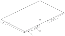
It is known in the industry of water heater manufacturing that a water heater bracket needs to be bent and formed in the machining process, and the bending and forming of the water heater bracket is mostly processed by adopting a bending and forming die of the water heater bracket. The bending forming processing of the water heater support is divided into large bending processing and small bending processing. The shape of the water heater bracket before bending is shown in fig. 1, the shape of the water heater bracket after bending is shown in fig. 2, the position of large bending is a position A of fig. 2, and the position of small bending is a position B of fig. 2.
At present, two sets of dies are used for bending and forming the water heater bracket. Two sets of dies are adopted to perform processing in two procedures, one set of dies performs processing aiming at large bending, and the other set of dies performs processing aiming at small bending. However, two work stations are required for two processes, and each work station needs to be equipped with one worker, so that the labor cost is high. Moreover, the material needs to be discharged and taken twice in the two-time processing, and the processing process is complicated. In addition, the manufacturing cost of the two sets of dies is high.
SUMMERY OF THE UTILITY MODEL
The to-be-solved technical problem of the utility model is to provide a water heater support forming die that bends, the cost of labor who adopts this mould is lower, the course of working is simple and convenient, manufacturing cost is lower.
In order to solve the problems, the following technical scheme is provided:
the utility model discloses a water heater support forming die that bends includes die holder and the upper die base of arranging side by side. The upper surface of the lower die base is fixedly provided with a horizontally arranged lower die plate, the lower die base corresponding to four sides of the lower die plate is provided with a limiting block for limiting the water heater support blank, and a space for facilitating bending of the water heater support blank is arranged between the limiting block and the corresponding side of the lower die plate. An upper template is horizontally arranged above the lower template, forming cutters are arranged on the lower plate surface of the upper template corresponding to the space, an upper pressing plate is horizontally arranged between the forming cutters and connected with the upper template through an upper spring, and the bottom of the upper pressing plate extends out of the lower surface of the forming cutters under the state that external force is not applied to the upper pressing plate. The water heater support blank is characterized in that the lower template corresponding to the small bending of the water heater support blank is provided with a yielding port, the lower die seat corresponding to the yielding port is provided with a sliding block, the sliding block and the lower die seat are in sliding fit towards one side close to and far away from the corresponding yielding port, a return spring is arranged between the sliding block and the lower die seat, the sliding block is provided with a punch towards the corresponding yielding port, the top of the sliding block is provided with an inclined plane, and the distance between the inclined plane and the corresponding yielding port is gradually increased from top to bottom. And the upper die base above the inclined plane is fixed with a wedge block, and the wedge block is matched with the inclined plane, so that after the wedge block descends to abut against the inclined plane, the reset spring is compressed, and the sliding block slides towards one side close to the corresponding yielding port.
The lower template is internally provided with at least two vertically arranged stripping ejector rods, the lower ends of the ejector rods are fixedly provided with stripping springs, the upper ends of the stripping ejector rods extend out of the upper plate surface of the lower template when the stripping springs are in an uncompressed state, and the stripping ejector rods extend into the lower template when the stripping springs are in a compressed state
The slider both sides all have the spacing strip, have the guide slot on the die holder that the slider corresponds, have the guide block in the guide slot, guide block and slider fixed connection, reset spring is located the guide block and is close to let between the guide slot one end of position mouthful, keeps away from and is fixed with the dog on the die holder that drift slider one end corresponds, and dog one side that is close to the slider is fixed with the copper.
Guide posts are arranged at four corners of the upper die base, and guide sleeves are arranged on the lower die base corresponding to the guide posts.
By adopting the scheme, the method has the following advantages:
because the utility model discloses a water heater support forming die's water heater support blank bends for a short time and all has the mouth of stepping down on the cope match-plate pattern that corresponds, all there is the slider on the die holder that the mouth of stepping down corresponds, be towards being close to between slider and die holder, keep away from the one side sliding form cooperation of the corresponding mouth of stepping down, there is reset spring between slider and die holder, all be fixed with on the slider towards corresponding the drift of letting a mouthful arranging, there is the inclined plane at the top of slider, the inclined plane is to corresponding the distance top-down grow gradually that lets between a mouthful, the cope match-plate pattern of inclined plane top all is fixed with the voussoir, voussoir and inclined plane looks adaptation. When the die is used, the upper die base is connected with a pressure head of a press, and the lower die base is fixed on a fixing plate of the press below the pressure head. When the water heater support is in work, a blank of the water heater support before forming is placed on the lower template, and four edges of the support are abutted to the corresponding limiting blocks; then, controlling the press to start, driving the upper die base to move downwards by a pressure head of the press, pressing the upper die plate on the water heater support blank, and clamping the water heater support blank; and then, the pressure head continues to move downwards, the upper spring is compressed, the upper pressure plate moves upwards, and the forming cutter is abutted against the periphery of the water heater support blank to perform large-bending forming. And then, after the large-bending forming is finished, the pressure head of the press drives the upper die base to continuously move downwards, the wedge block abuts against the inclined surface of the sliding block, the reset spring is compressed, the wedge block moves towards one side of the allowance opening, and the punch abuts against the small bending part of the formed water heater support blank to perform small-bending forming. And finally, the pressure head of the press drives the upper die base to move upwards and reset, and then bending forming is completed. Adopt this mould punching press once to accomplish two and bend, adopt a station can accomplish twice processing of bending promptly to only need a staff can accomplish the shaping of bending of water heater support blank, the cost of labor that has significantly reduced. Moreover, the bending can be finished twice only by one-time operation, and the working process is greatly simplified. In addition, only one set of die can greatly reduce the manufacturing cost.
Drawings
FIG. 1 is a schematic structural view of a water heater bracket before bending forming processing in the prior art;
FIG. 2 is a schematic structural view of a water heater bracket after bending forming processing in the prior art;
fig. 3 is a schematic structural view of the bending and forming mold for the water heater bracket of the present invention;
fig. 4 is a die assembly state diagram of the bending and forming die for the water heater bracket of the utility model;
FIG. 5 is a schematic cross-sectional view taken along line D-D of FIG. 4;
fig. 6 is a schematic perspective view of the water heater bracket bending and forming mold of the utility model before pressing.
Detailed Description
The present invention will be described in further detail with reference to the accompanying drawings.
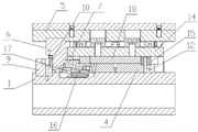
As shown in fig. 3 to 6, the bending and forming die for the water heater bracket of the present invention comprises a lower die holder 1 and an upper die holder 5 which are arranged side by side. The upper surface of the lower die holder 1 is fixedly provided with a lower die plate 4 which is horizontally arranged, the lower die holder 1 corresponding to four sides of the lower die plate 4 is provided with a limiting block 12 for limiting the blank of the water heater support, and a space for bending the blank of the water heater support is arranged between the limiting block 12 and the corresponding side of the lower die plate 4. An upper template 14 is horizontally arranged above the lower template 4, forming knives 15 are arranged on the lower plate surface of the upper template 14 corresponding to the space, upper pressing plates 18 are horizontally arranged among the forming knives 15, the upper pressing plates 18 are connected with the upper template 14 through upper springs, the upper pressing plates 18 are in an external force non-receiving state, and the bottoms of the upper pressing plates 18 extend out of the lower surfaces of the forming knives 15. All there is the mouth of stepping down 19 on the lower bolster 4 that the water heater support blank is bent for a short time and corresponds, all there is slider 7 on the die holder 1 that the mouth of stepping down 19 corresponds of stepping down, be towards being close to, keeping away from the one side sliding form cooperation of the mouth of stepping down 19 that corresponds between slider 7 and the die holder 1, there is reset spring 16 between slider 7 and die holder 1, all be fixed with on the slider 7 towards corresponding drift 20 of stepping down 19 arrangement of stepping down, there is inclined plane 8 at the top of slider 7, inclined plane 8 is to corresponding the distance top-down grow gradually that lets between the mouth of stepping down 19. And wedge blocks 6 are fixed on the upper die bases 5 above the inclined planes 8, and the wedge blocks 6 are matched with the inclined planes 8, so that after the wedge blocks 6 descend to abut against the inclined planes 8, the return springs 16 are compressed, and the sliding blocks 7 slide towards one sides close to the corresponding relief openings 19.
The lower template 4 is internally provided with at least two vertically arranged stripping ejector rods 13, the lower ends of the ejector rods are fixedly provided with stripping springs, the upper ends of the stripping ejector rods 13 extend out of the upper plate surface of the lower template 4 when the stripping springs are in an uncompressed state, and the stripping ejector rods 13 extend into the lower template 4 when the stripping springs are in a compressed state
The two sides of the sliding block 7 are both provided with a limiting strip 11, a guide groove is formed in the lower die holder 1 corresponding to the sliding block 7, a guide block 17 is arranged in the guide groove, the guide block 17 is fixedly connected with the sliding block 7, the reset spring 16 is positioned between the guide block 17 and one end of the guide groove close to the corresponding yielding port 19, a stop block 9 is fixed on the lower die holder 1 corresponding to one end of the sliding block 7 far away from the punch 20, and a copper plate 10 is fixed on one side of the stop block 9 close to the sliding block 7.
When the die is used, the upper die holder 5 is connected with a pressure head of a press, and the lower die holder 1 is fixed on a fixing plate of the press below the pressure head. During operation, the blank of the water heater support before forming is placed on the lower template 4, so that four sides of the support are abutted to the corresponding limiting blocks 12. And then, controlling the press to start, driving the upper die holder 5 to move downwards by a pressure head of the press, pressing the upper die plate 14 on the water heater support blank, and clamping the water heater support blank. And then, the pressure head continues to move downwards, the upper spring is compressed, the upper pressing plate 18 moves upwards, and the forming cutter 15 abuts against the periphery of the water heater support blank to perform large-bending forming. And then, after the large bending forming is finished, the pressure head of the press drives the upper die holder 5 to continuously move downwards, the wedge block 6 abuts against the inclined surface 8 of the slide block 7, the return spring 16 is compressed, the wedge block 6 moves towards one side of the relief opening 19, and the punch 20 abuts against the small bending part of the formed water heater support blank to perform small bending forming. And finally, the pressure head of the press drives the upper die holder 5 to move upwards and reset, and then the bending molding is completed.
Claims (4)
1. The bending forming die for the water heater support comprises a lower die holder (1) and an upper die holder (5) which are arranged side by side; the upper surface of the lower die holder (1) is fixedly provided with a horizontally arranged lower die plate (4), the lower die holders (1) corresponding to the four side edges of the lower die plate (4) are respectively provided with a limiting block (12) for limiting the water heater support blank, and a space for bending the water heater support blank is formed between each limiting block (12) and the corresponding side edge of the lower die plate (4); an upper template (14) is horizontally arranged above the lower template (4), forming cutters (15) are arranged on the lower plate surfaces of the upper templates (14) corresponding to the intervals, upper pressure plates (18) are horizontally arranged among the forming cutters (15), the upper pressure plates (18) are connected with the upper template (14) through upper springs, the upper pressure plates (18) are in an external force non-receiving state, and the bottoms of the upper pressure plates (18) extend out of the lower surfaces of the forming cutters (15); the water heater support blank small bending die is characterized in that a yielding opening (19) is formed in a lower template (4) corresponding to a small bending of the water heater support blank, a sliding block (7) is arranged on a lower die base (1) corresponding to the yielding opening (19), the sliding block (7) is in sliding fit with the lower die base (1) towards one side close to and far away from the corresponding yielding opening (19), a reset spring (16) is arranged between the sliding block (7) and the lower die base (1), a punching head (20) which is arranged towards the corresponding yielding opening (19) is fixed on the sliding block (7), an inclined surface (8) is formed in the top of the sliding block (7), and the distance between the inclined surface (8) and the corresponding yielding opening (19) is gradually increased from top to bottom; and the upper die base (5) above the inclined plane (8) is fixedly provided with a wedge block (6), the wedge block (6) is matched with the inclined plane (8), so that after the wedge block (6) descends to abut against the inclined plane (8), the return spring (16) is compressed, and the sliding block (7) slides towards one side close to the corresponding position-giving opening (19).
2. The bending and forming die for the water heater support frame as claimed in claim 1, wherein at least two vertically arranged stripping ejector rods (13) are arranged in the lower die plate (4), stripping springs are fixed at the lower ends of the ejector rods, the upper ends of the stripping ejector rods (13) extend out of the upper plate surface of the lower die plate (4) when the stripping springs are in an uncompressed state, and the stripping ejector rods (13) extend into the lower die plate (4) when the stripping springs are in a compressed state.
3. The bending and forming die for the water heater support according to claim 1, wherein the two sides of the sliding block (7) are provided with a limiting strip (11), the lower die holder (1) corresponding to the sliding block (7) is provided with a guide groove, a guide block (17) is arranged in the guide groove, the guide block (17) is fixedly connected with the sliding block (7), the reset spring (16) is arranged between the guide block (17) and one end of the guide groove close to the corresponding yielding port (19), a stop block (9) is fixed on the lower die holder (1) corresponding to one end of the sliding block (7) far away from the punch (20), and a copper plate (10) is fixed on one side of the stop block (9) close to the sliding block (7).
4. The bending and forming die for the water heater support according to any one of claims 1 to 3, wherein guide posts (3) are arranged at four corners of the upper die holder (5), and guide sleeves (2) are arranged on the lower die holder (1) corresponding to the guide posts (3).
Priority Applications (1)
| Application Number | Priority Date | Filing Date | Title |
|---|---|---|---|
| CN202222300926.5U CN218134240U (en) | 2022-08-31 | 2022-08-31 | Bending forming die for water heater support |
Applications Claiming Priority (1)
| Application Number | Priority Date | Filing Date | Title |
|---|---|---|---|
| CN202222300926.5U CN218134240U (en) | 2022-08-31 | 2022-08-31 | Bending forming die for water heater support |
Publications (1)
| Publication Number | Publication Date |
|---|---|
| CN218134240U true CN218134240U (en) | 2022-12-27 |
Family
ID=84557600
Family Applications (1)
| Application Number | Title | Priority Date | Filing Date |
|---|---|---|---|
| CN202222300926.5U Active CN218134240U (en) | 2022-08-31 | 2022-08-31 | Bending forming die for water heater support |
Country Status (1)
| Country | Link |
|---|---|
| CN (1) | CN218134240U (en) |
-
2022
- 2022-08-31 CN CN202222300926.5U patent/CN218134240U/en active Active
Similar Documents
| Publication | Publication Date | Title |
|---|---|---|
| CN101875081A (en) | Automotive wire bundle punching die | |
| CN209773246U (en) | Trimming and flanging die | |
| CN201676963U (en) | Punching mould of automobile wire bundle | |
| CN211866426U (en) | Stable fashioned automobile inner panel spare stamping die | |
| CN218134240U (en) | Bending forming die for water heater support | |
| CN207735428U (en) | A kind of hydraulic pump bracket die | |
| CN213944550U (en) | Automobile side beam reinforcing plate flanging reshaping and side flanging punching die assembly die | |
| CN213495967U (en) | Stamping die of wiring fixing plate | |
| CN213887918U (en) | Material clamping mechanism | |
| CN211489311U (en) | Corner cut forming integrated die | |
| CN213530434U (en) | Automatic forming and stamping die for upper cover plate of quick-release lock part | |
| CN213256598U (en) | Integrated processing device for impeller blade of hydraulic torque converter | |
| CN210847981U (en) | Composite die for cutting, bending and one-step forming | |
| CN214133585U (en) | Automatic forming stamping die for elastic sheet on quick-release lock part | |
| CN210450556U (en) | Continuous mould of stay tube | |
| CN217748924U (en) | Split type fashioned five metals precision mould | |
| CN216540469U (en) | Stamping progressive die | |
| CN219746045U (en) | Sheet metal part continuous stamping die | |
| CN219093351U (en) | Stamping die for precise panel bracket | |
| CN211027763U (en) | Side punching die | |
| CN216461199U (en) | Multidirectional bending forming's sheet metal component upgrades mould | |
| CN218310360U (en) | Continuous die for stamping and integrating laminated products | |
| CN213495966U (en) | Stamping structure of wiring fixing plate | |
| CN216989505U (en) | Hardware mould and inside reverse bending device thereof | |
| CN212857395U (en) | Support production frock for car |
Legal Events
| Date | Code | Title | Description |
|---|---|---|---|
| GR01 | Patent grant | ||
| GR01 | Patent grant |