CN218123761U - Connector and wire-to-board connector - Google Patents
Connector and wire-to-board connector Download PDFInfo
- Publication number
- CN218123761U CN218123761U CN202222027830.6U CN202222027830U CN218123761U CN 218123761 U CN218123761 U CN 218123761U CN 202222027830 U CN202222027830 U CN 202222027830U CN 218123761 U CN218123761 U CN 218123761U
- Authority
- CN
- China
- Prior art keywords
- connector
- groove
- rear cover
- insulator
- shielding member
- Prior art date
- Legal status (The legal status is an assumption and is not a legal conclusion. Google has not performed a legal analysis and makes no representation as to the accuracy of the status listed.)
- Active
Links
Images


Landscapes
- Details Of Connecting Devices For Male And Female Coupling (AREA)
Abstract
The utility model discloses a connector and line to board connector, the connector includes first connector main part, the insulator, lid and stretching strap behind the connector, at least part of insulator inlays and locates in first connector main part, be provided with the hasp on the insulator and be used for being connected with another connector cooperation, first connector main part is located to lid behind the connector, the lid forms the mounting groove behind the connector, the top surface of lid corresponds the mounting groove behind the connector and is provided with the butt arch, the stretching strap runs through the mounting groove in order to be connected with the hasp, and stretching strap and the protruding butt of butt, the stretching strap is used for the atress to drive the hasp and breaks away from another connector, wherein, the stretching strap not only can be through the application of force of being connected with the hasp, can also through with the protruding butt of lid behind the connector lid behind to lid application of force behind the connector, be convenient for the connector with break away from the unblock of another connector, the reliability is higher.
Description
Technical Field
The utility model relates to a connector technical field, in particular to connector and line to board connector.
Background
Under the vigorous development of the communication industry, various connection interfaces continuously pursue a reliable and stable connection mode, so that the interlocking and unlocking structures of the connection interfaces are rapidly developed and diversified. For example, an MCIO (Mini Cool Edge IO, I/O interface defined by the association) connector is a connector applied to a server and a switch for high-speed transmission, and has a small product volume and reliable and stable connection. Similar to the MCIO connector, a metal elastic sheet lock catch is usually used as a locking structure between two connectors, and unlocking is realized by pressing an elastic sheet or pulling a pull belt.
The connector that is provided with the stretching strap at present is generally with the stretching strap directly to be connected the cooperation with the hasp and realize the function of pulling the hasp, and the stretching strap produces the condition such as slip easily, and the reliability is relatively poor.
SUMMERY OF THE UTILITY MODEL
The utility model provides a connector and line to board connector to the relatively poor technical problem of reliability is connected to the stretching strap of connector among the solution prior art.
In order to solve the above technical problem, the utility model discloses a technical scheme provide a connector, include:
a first connector body;
the insulator is at least partially embedded in the first connector body, and a lock catch is arranged on the insulator and is used for being matched and connected with the other connector;
the connector rear cover is covered on the first connector main body, a mounting groove is formed in the connector rear cover, and a butting bulge is arranged on the top surface of the connector rear cover corresponding to the mounting groove;
the stretching strap runs through the mounting groove in order to be connected with the hasp, just the stretching strap with the protruding butt of butt, the stretching strap is used for the atress to drive the hasp breaks away from another connector.
In a specific embodiment, the drawstring comprises a drawstring main body and a connecting portion, wherein the drawstring main body is connected with the connecting portion, the drawstring main body penetrates through the mounting groove, and the connecting portion is abutted to the abutting protrusion.
In a specific embodiment, the thickness of the drawstring main body is smaller than or equal to the thickness of the installation groove, and the thickness of the connecting part is larger than the thickness of the installation groove.
In a specific embodiment, the drawstring further comprises a handheld portion, the handheld portion is connected to one end, away from the connecting portion, of the drawstring main body, and the width of the handheld portion is larger than that of the drawstring main body.
In one embodiment, the latch comprises:
the lock catch main body is connected with the insulator and is used for being matched and connected with another connector;
the connecting piece, with the hasp main part is connected, the connecting piece is formed with the spread groove, the stretching strap passes through the spread groove with the connecting piece is connected.
In an embodiment, the first connector body is provided with a first receiving groove and a shielding element corresponding to the first receiving groove, the lock is received in the first receiving groove, and at least a portion of the lock is shielded by the shielding element.
In an embodiment, the protection element protrudes from the first connector body, and the protection element is formed with a second receiving groove communicating with the first receiving groove for receiving the connector.
In a specific embodiment, the protection member is disposed in a strip shape for shielding at least a portion of the connection member, and the connection portion is disposed between the protection member and the connector rear cover.
In an embodiment, the protection element includes a protection element main body portion arranged in a strip shape and a protrusion portion protruding from the protection element main body portion toward the connector rear cover, the protection element is used for shielding the connecting element, and the connecting portion is clamped between the protection element and the connector rear cover.
In order to solve the technical problem, the utility model discloses a further technical scheme provides a line to board connector, including line end connector and board end connector, line end connector is foretell connector, board end connector includes the second connector main part, be formed with the spacing groove in the second connector main part, the hasp with the spacing groove cooperation is spacing.
The utility model discloses the connector includes first connector main part, the insulator, lid and stretching strap behind the connector, at least part of insulator inlays locates in first connector main part, it is used for being connected with another connector cooperation to be provided with the hasp on the insulator, first connector main part is located to lid behind the connector, the lid forms there is the mounting groove behind the connector, the top surface of lid corresponds the mounting groove behind the connector and is provided with the butt arch, the stretching strap runs through the mounting groove in order to be connected with the hasp, and stretching strap and the protruding butt of butt, the stretching strap is used for the atress to drive the hasp and breaks away from another connector, wherein, the stretching strap not only can be through the application of force of being connected with the hasp, can also through with the protruding butt of lid behind the connector lid application of force behind the connector, be convenient for the unblock of breaking away from of connector and another connector, the reliability is higher.
Drawings
In order to more clearly illustrate the technical solutions in the embodiments of the present invention, the drawings used in the description of the embodiments will be briefly described below, and it is obvious that the drawings in the following description are only some embodiments of the present invention, and for those skilled in the art, other drawings can be obtained without inventive work, wherein:
fig. 1 is a schematic perspective view of an embodiment of the connector of the present invention;
fig. 2 is an exploded view of an embodiment of the connector of the present invention;
fig. 3 is a schematic cross-sectional view of an embodiment of the connector of the present invention;
fig. 4 is a schematic perspective view of a first connector body according to an embodiment of the present invention;
fig. 5 is a schematic perspective view of another embodiment of the connector of the present invention;
fig. 6 is an exploded view of another embodiment of the connector of the present invention;
fig. 7 is a schematic perspective view of a rear cover of the connector according to another embodiment of the present invention;
fig. 8 is a schematic perspective view of another embodiment of the connector of the present invention;
fig. 9 is an exploded view of another embodiment of the connector of the present invention;
fig. 10 is a schematic perspective view of a rear cover of a connector according to another embodiment of the present invention;
fig. 11 is a schematic perspective view of an embodiment of a wire-to-board connector according to the present invention;
fig. 12 is a schematic perspective view of another embodiment of a wire-to-board connector according to the present invention.
Detailed Description
The technical solutions in the embodiments of the present invention will be described clearly and completely with reference to the accompanying drawings in the embodiments of the present invention, and it is obvious that the described embodiments are only some embodiments of the present invention, not all embodiments. Based on the embodiments in the present invention, all other embodiments obtained by a person skilled in the art without creative efforts all belong to the protection scope of the present invention.
The terms "first" and "second" in this application are used for descriptive purposes only and are not to be construed as indicating or implying relative importance or implicitly indicating the number of technical features indicated. In the description of the present application, "plurality" means at least two, e.g., two, three, etc., unless explicitly specifically limited otherwise. Furthermore, the terms "include" and "have," as well as any variations thereof, are intended to cover non-exclusive inclusions. For example, a process, method, system, article, or apparatus that comprises a list of steps or elements is not limited to only those steps or elements listed, but may alternatively include other steps or elements not listed, or inherent to such process, method, article, or apparatus. And the term "and/or" is only one kind of association relationship describing the associated object, and means that there may be three kinds of relationships, for example, a and/or B, and may mean: a exists alone, A and B exist simultaneously, and B exists alone. In addition, the character "/" herein generally indicates that the former and latter related objects are in an "or" relationship.
Referring to fig. 1 to 4, an embodiment of the connector 10 of the present invention includes a first connector body 100 and an insulator 200, the first connector body 100 is formed with a first receiving groove 110, a protection part 120 is disposed on the first connector body 100 corresponding to the first receiving groove 110, the insulator 200 is connected to the first connector body 100, a latch 300 is disposed on the insulator 200, the latch 300 is received in the first receiving groove 110, and at least a portion of the latch 300 is shielded by the protection part 120, so as to prevent the latch 300 from being mistakenly pressed or being mistakenly pressed by other components such as a cable, the connector 10 is not easily detached, the reliability of connection is better, the strength of the first connector body 100 can be enhanced by disposing the protection part 120, the thickness of the first connector body 100 can be increased, the difficulty of manufacturing the first connector body 100 is lower, and the connector 10 has better manufacturability.
In the embodiment, the first connector body 100 may be made of a plastic material, and the latch 300 is made of a metal material, so that the strength of the latch 300 is higher, and the first connector body 100 and the latch 300 can be conveniently locked.
In this embodiment, the insulator 200 may be made of a plastic material, which can perform an insulating function to prevent short circuit.
In this embodiment, the latch 300 includes a latch main body 310 and a pressing member 320, the latch main body 310 is connected to the insulator 200, the latch main body 310 is used for being connected to another connector in a matching manner, the pressing member 320 is connected to the latch main body 310, so that the latch main body 310 can be separated from the other connector after the pressing member 320 is pressed down by a force, and the shielding member 120 is used for shielding at least a portion of the pressing member 320, so that the pressing member 320 is not easily pressed by mistake or pressed by mistake.
In this embodiment, the front-back direction shown in fig. 3 is defined as a first direction, the left-right direction is defined as a second direction, and the up-down direction is defined as a third direction.
In the present embodiment, the shielding element 120 spans two sides of the first receiving groove 110 along the first direction, and a width of the shielding element 120 along a second direction perpendicular to the first direction is smaller than a width of the pressing element 320 along the second direction, so that the shielding element 120 can shield a portion of the pressing element 320, the pressing element 320 is not easily pressed or pressed by mistake, and the connector 10 can be unlocked by pressing the portion of the pressing element 320 that is not shielded when the connector 10 needs to be unlocked.
In the embodiment, the shielding element 120 protrudes from the first connector body 100 along the third direction, and the shielding element 120 is formed with a second receiving groove 121 communicating with the first receiving groove 110 for receiving the pressing element 320, so as to prevent the shielding element 120 from interfering with the latch 300.
In this embodiment, the latch main body 310 includes a first elastic sheet 311 and a second elastic sheet 312, a first end of the first elastic sheet 311 is connected to the insulator 200 and the pressing member 320, and a second end of the first elastic sheet 311 is connected to the second elastic sheet 312, so that the pressing member 320 can drive the first elastic sheet 311 to move closer to or away from the second elastic sheet 312 by force, so as to fasten another connector.
In this embodiment, the first resilient piece 311 is provided with a first limiting protrusion 313, the first limiting protrusion 313 is used for being matched with a first limiting groove (not shown) of another connector for limiting, the second resilient piece 312 is provided with a second limiting groove 314, the first connector main body 100 is provided with a second limiting protrusion 111, and the second limiting protrusion 111 is matched with the second limiting groove 314 for limiting, so that the connection between the latch 300 and the first connector main body 100 is more stable, and the connection between the latch 300 and another connector is more stable.
In this embodiment, the pressing member 320 is provided with a protrusion 321, and the protrusion 321 is disposed in a long strip shape, so that friction between the surface of the pressing member 320 and an urging object (e.g., a finger) can be increased, and the pressing member 320 can be easily urged.
In the present embodiment, the connector 10 further includes a circuit board 400 and a connector rear cover 500, at least a portion of the insulator 200 is embedded in the first connector body 100, the circuit board 400 is embedded in the insulator 200, and the connector rear cover 500 is covered on the first connector body 100, so that the circuit board 400 can be fixed in the insulator 200.
In this embodiment, the first connector body 100 may further be formed with a circuit board mounting groove 130, the first connector body 100 is further provided with a guide rib 140 corresponding to the circuit board mounting groove 130, and the circuit board 400 can be inserted into the circuit board mounting groove 130 along the guide rib 140.
In this embodiment, the first connector body 100 may further be formed with a receiving space 150 and an injection hole 160, so that the insulator 200 is injection-molded in the receiving space 150 through the injection hole 160, and the overall structure of the connector 10 is more compact and stable.
In this embodiment, the first connector body 100 may further have a snap hole 170, the connector back cover 500 is provided with a snap protrusion 510, the snap hole 170 and the snap protrusion 510 cooperate to realize a snap, so that the connection between the first connector body 100 and the connector back cover 500 is more stable.
In other embodiments, the first connector body 100 may be provided with a snap protrusion, and the connector rear cover 500 may be provided with a corresponding snap hole, which is not limited herein.
In this embodiment, the first connector body 100 may further be formed with a buckle pre-assembly groove 180, and the connector rear cover 500 is further provided with a buckle 520, where the buckle pre-assembly groove 180 and the buckle 520 are matched to realize limiting.
In this embodiment, the connector 10 may be a wire end connector, and the cable 20 is connected to the circuit board 400 through the connector rear cover 500.
In other embodiments, the connector 10 may also be a plate-end connector, and is not limited herein.
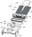
Referring to fig. 5 to 7, another embodiment of the connector 10 of the present invention includes a first connector main body 100, an insulator 200, a connector rear cover 500 and a pull strip 600, at least a portion of the insulator 200 is embedded in the first connector main body 100, a latch 300 is disposed on the insulator 200, the latch 300 is used for being connected to another connector in a matching manner, the connector rear cover 500 is covered on the first connector main body 100, a mounting groove 530 is formed on the connector rear cover 500, a top surface of the connector rear cover 500 is provided with an abutting projection 540 corresponding to the mounting groove 530, the pull strip 600 runs through the mounting groove 530 to be connected to the latch 300, the pull strip 600 abuts against the abutting projection 540, and the pull strip 600 is used for being forced to drive the latch 300 to disengage from another connector, wherein the pull strip 600 not only can apply force to the connector rear cover 500 through being connected to the latch 300, but also can apply force to the connector rear cover 500 through the abutting projection 540 of the connector rear cover 500, thereby facilitating the disengagement unlocking of the connector 10 from another connector, and the reliability is higher.
In the present embodiment, the structure of the latch body 330 is similar to that of the latch body 310 in the above-mentioned embodiment of the connector 10, and is not described herein again.
In this embodiment, the pull strap 600 includes a connected pull strap main body 610 and a connecting portion 620, the pull strap main body 610 penetrates through the mounting groove 530, the connecting portion 620 is connected to the latch 300 and abuts against the abutting protrusion 540, so that the connector rear cover 500 can be forced to drive the connector 10 to move.
In this embodiment, the thickness of the drawtape main body 610 is less than or equal to the thickness of the installation groove 530, which facilitates the installation of the drawtape 600, and the thickness of the connection part 620 is greater than the thickness of the installation groove 530, which can prevent the connection part 620 from falling off from the installation groove 530.
In this embodiment, the pull tab 600 may further include a handle portion 630, the handle portion 630 is connected to an end of the pull tab main body 610 far away from the connecting portion 620, and the width of the handle portion 630 is greater than that of the pull tab main body 610, so as to facilitate the user to hold the pull tab.
In this embodiment, the latch 300 includes a latch main body 330 and a connecting member 340, the latch main body 330 is connected to the insulator 200, the latch main body 330 is used for being connected to another connector in a matching manner, the connecting member 340 is connected to the latch main body 330, a connecting groove 341 is formed in the connecting member 340, and the pull belt 600 is connected to the connecting member 340 through the connecting groove 341, so that the pull belt 600 can drive the latch 300 to move.
In the embodiment, the first connector body 100 is provided with the first receiving groove 110 and the shielding element 120 corresponding to the first receiving groove 110, the latch 300 is received in the first receiving groove 110, and at least a portion of the latch 300 is shielded by the shielding element 120, so that the connector 340 can be prevented from being pressed by mistake or being pressed by mistake to cause the connector 10 to be separated from another connector. In the present embodiment, by providing the protection piece 120, the latch 300 can be prevented from being mistakenly pressed or being mistakenly pressed by other components such as a cable, the connector 10 is not easily detached, the connection reliability is better, the strength of the first connector body 100 can be enhanced by providing the protection piece 120, the thickness of the first connector body 100 can be increased, the difficulty in preparing the first connector body 100 is lower, the connector 10 has better manufacturability, and the unlocking of the connector can be facilitated by providing the pull belt 600.
Referring to fig. 4, in the present embodiment, the protection element 120 is spanned across two sides of the first receiving groove 110 along the first direction, and a width of the protection element 120 along a second direction perpendicular to the first direction is smaller than a width of the connection element 340 along the second direction, so that the protection element 120 can shield a portion of the connection element 340, and the connection element 340 is not easily pressed or pressed by mistake.
In the embodiment, the shielding element 120 protrudes from the first connector body 100 along the third direction, and the shielding element 120 is formed with a second receiving groove 121 communicating with the first receiving groove 110 for receiving the connecting element 340, so as to prevent the shielding element 120 from interfering with the latch 300.
In this embodiment, the protection member 120 is disposed in a strip shape to shield at least a portion of the connection member 340, and the connection portion 620 is disposed between the protection member 120 and the connector rear cover 500, so that when the pull strap 600 is damaged or is not conveniently pulled, the portion of the connection member 340 exposed to the protection member 120 can be further used for being stressed to unlock.
Referring to fig. 8 and 9, another embodiment of the connector 10 of the present invention includes a first connector body 100, an insulator 200, and a pull strap 600, and the structures of the insulator 200 and the pull strap 600 are referred to the above embodiment of the connector 10, and are not described herein again.
Referring to fig. 10, the difference between the present embodiment and the above embodiments is that in the present embodiment, the protection element 190 includes a protection element main body portion 191 arranged in a strip shape and a protrusion portion 192 protruding from the protection element main body portion 191 toward the connector rear cover 500, the protection element 190 is used for shielding all of the connecting element 340, so that the shielding effect is better, the connecting element 340 is further prevented from being pressed or pressed by mistake, the connecting element 340 is clamped between the protection element 120 and the connector rear cover 500, and the connection between the pull strip 600 and the first connector main body 100 is more stable.
In the present embodiment, the connector 10 further includes a circuit board 400, the circuit board 400 is embedded in the insulator 200, and the connector rear cover 500 can fix the circuit board 400 in the insulator 200.
In the present embodiment, the circuit board 400 is used for connection with the cable 20.
Referring to fig. 11 and 12, the wire-to-board connector of the present invention includes a wire end connector and a board end connector 30, the wire end connector is the connector 10, the board end connector 30 includes a second connector body 700, a limiting groove 710 is formed on the second connector body 700, and the latch 300 is matched with the limiting groove 710 for limiting. In the present embodiment, the protection piece 120 is provided to prevent the latch 300 from being pressed by mistake or being pressed by mistake by other components such as a cable, so that the connector 10 is not easy to fall off, the connection reliability is better, the strength of the first connector body 100 can be enhanced by providing the protection piece 120, the thickness of the first connector body 100 can be increased, the difficulty in manufacturing the first connector body 100 is lower, and the connector 10 has better manufacturability.
The above only is the embodiment of the present invention, not limiting the patent scope of the present invention, all the equivalent structures or equivalent processes that are used in the specification and the attached drawings or directly or indirectly applied to other related technical fields are included in the patent protection scope of the present invention.
Claims (10)
1. A connector, comprising:
a first connector body;
the insulator is at least partially embedded in the first connector body, and a lock catch is arranged on the insulator and is used for being matched and connected with the other connector;
the connector rear cover is covered on the first connector main body, a mounting groove is formed in the connector rear cover, and a butting bulge is arranged on the top surface of the connector rear cover corresponding to the mounting groove;
the stretching strap runs through the mounting groove in order to be connected with the hasp, just the stretching strap with the protruding butt of butt, the stretching strap is used for the atress to drive the hasp breaks away from another connector.
2. The connector of claim 1, wherein the drawstring includes a connected drawstring body and a connecting portion, the drawstring body extending through the mounting slot, the connecting portion abutting the abutment protrusion.
3. The connector of claim 2, wherein a thickness of the drawtape body is less than or equal to a thickness of the mounting groove, and a thickness of the connection portion is greater than the thickness of the mounting groove.
4. The connector of claim 2, wherein the pull strap further includes a hand grip connected to an end of the pull strap body distal from the connection portion, the hand grip having a width greater than a width of the pull strap body.
5. The connector of claim 2, wherein the latch comprises:
the lock catch main body is connected with the insulator and is used for being matched and connected with another connector;
the connecting piece, with the hasp main part is connected, the connecting piece is formed with the spread groove, the stretching strap passes through the spread groove with the connecting piece is connected.
6. The connector of claim 5, wherein the first connector body is provided with a first receiving groove and a shielding element corresponding to the first receiving groove, the lock catch is received in the first receiving groove, and at least a portion of the lock catch is shielded by the shielding element.
7. The connector according to claim 6, wherein the shielding member is provided to protrude from the first connector body, and the shielding member is formed with a second receiving groove communicating with the first receiving groove for receiving the connecting member.
8. The connector according to claim 6, wherein the shielding member is provided in a strip shape for shielding at least a portion of the connecting member, and the connecting portion is provided between the shielding member and the connector rear cover.
9. The connector according to claim 6, wherein the shielding member includes a shielding member main body portion arranged in a bar shape and a protruding portion protruding from the shielding member main body portion toward the connector rear cover, the shielding member is configured to shield the connecting member, and the connecting portion is clamped between the shielding member and the connector rear cover.
10. A wire-to-board connector, comprising a wire end connector and a board end connector, wherein the wire end connector is the connector as claimed in any one of claims 1 to 9, the board end connector comprises a second connector body, a limiting groove is formed on the second connector body, and the latch is matched with the limiting groove for limiting.
Priority Applications (1)
| Application Number | Priority Date | Filing Date | Title |
|---|---|---|---|
| CN202222027830.6U CN218123761U (en) | 2022-08-02 | 2022-08-02 | Connector and wire-to-board connector |
Applications Claiming Priority (1)
| Application Number | Priority Date | Filing Date | Title |
|---|---|---|---|
| CN202222027830.6U CN218123761U (en) | 2022-08-02 | 2022-08-02 | Connector and wire-to-board connector |
Publications (1)
| Publication Number | Publication Date |
|---|---|
| CN218123761U true CN218123761U (en) | 2022-12-23 |
Family
ID=84521923
Family Applications (1)
| Application Number | Title | Priority Date | Filing Date |
|---|---|---|---|
| CN202222027830.6U Active CN218123761U (en) | 2022-08-02 | 2022-08-02 | Connector and wire-to-board connector |
Country Status (1)
| Country | Link |
|---|---|
| CN (1) | CN218123761U (en) |
-
2022
- 2022-08-02 CN CN202222027830.6U patent/CN218123761U/en active Active
Similar Documents
| Publication | Publication Date | Title |
|---|---|---|
| TWI657626B (en) | Connector | |
| US5401179A (en) | Locking mechanism for a connector assembly of low engaging/disengaging force type | |
| KR100673281B1 (en) | Structure for interlocking connectors | |
| EP1369964B1 (en) | Connector Position Assurance Device | |
| EP0189979B1 (en) | Electrical connector | |
| TWM595343U (en) | Connector | |
| JP2000003763A (en) | Connector locking mechanism | |
| US6149450A (en) | Smart card adapter latch | |
| KR20020046947A (en) | Connector assembly having an interlocking system | |
| JPH0613130A (en) | Electric-plug coupling device having half part of casing which can be engaged | |
| JPH11512222A (en) | Ribbon cable connector assembly | |
| CN113437576A (en) | First connector, second connector and electric connector combination | |
| US7182622B2 (en) | Electrical connector assembly | |
| CN210779276U (en) | Connector with a locking member | |
| CN210007015U (en) | Electrical connector | |
| CN218123761U (en) | Connector and wire-to-board connector | |
| JPH11503269A (en) | Connector assembly for ribbon cable | |
| US8425248B2 (en) | Plug electrical connector with elastic latch | |
| JP5821564B2 (en) | Electrical connector | |
| CN218070431U (en) | Connector and wire-to-board connector | |
| CN210007025U (en) | Electrical connector | |
| US20220271455A1 (en) | Electrical connector assembly | |
| CN210779297U (en) | Connector with a locking member | |
| CN212257885U (en) | Connector and electric connecting device | |
| CN218070438U (en) | Plug connector |
Legal Events
| Date | Code | Title | Description |
|---|---|---|---|
| GR01 | Patent grant | ||
| GR01 | Patent grant |