CN218115285U - Waste heat collecting device for annealing kiln - Google Patents
Waste heat collecting device for annealing kiln Download PDFInfo
- Publication number
- CN218115285U CN218115285U CN202222710441.3U CN202222710441U CN218115285U CN 218115285 U CN218115285 U CN 218115285U CN 202222710441 U CN202222710441 U CN 202222710441U CN 218115285 U CN218115285 U CN 218115285U
- Authority
- CN
- China
- Prior art keywords
- mounting
- casing
- wall
- box
- threaded rod
- Prior art date
- Legal status (The legal status is an assumption and is not a legal conclusion. Google has not performed a legal analysis and makes no representation as to the accuracy of the status listed.)
- Active
Links
Images


Classifications
-
- Y—GENERAL TAGGING OF NEW TECHNOLOGICAL DEVELOPMENTS; GENERAL TAGGING OF CROSS-SECTIONAL TECHNOLOGIES SPANNING OVER SEVERAL SECTIONS OF THE IPC; TECHNICAL SUBJECTS COVERED BY FORMER USPC CROSS-REFERENCE ART COLLECTIONS [XRACs] AND DIGESTS
- Y02—TECHNOLOGIES OR APPLICATIONS FOR MITIGATION OR ADAPTATION AGAINST CLIMATE CHANGE
- Y02P—CLIMATE CHANGE MITIGATION TECHNOLOGIES IN THE PRODUCTION OR PROCESSING OF GOODS
- Y02P10/00—Technologies related to metal processing
- Y02P10/25—Process efficiency
Abstract
The utility model relates to a glass production technical field just discloses an annealing kiln waste heat collection device, which comprises a housin, the bottom left and right sides of casing all is provided with quantity and is two supporting legss, the left side of casing is provided with the heat exchange tube that one end extends to its right side, the top of casing is provided with the box, the top of box is provided with the intake pipe that one end extends to its inside. This annealing kiln waste heat collection device, remove the position restriction to the installation piece through twisting the hand wheel, alright pulling installation piece left at this moment comes the framework to take out from the inside of box, thereby made things convenient for and cleared up the filter screen, drive installation pipe whole left and right sides reciprocating motion through starting driving motor, make the nozzle enlarge the scope of supplying gas, make the hot-air evenly distributed in the casing, as far as possible make the hot-air contact with the outside of heat exchange tube, improve the heating effect to the heat exchange tube, and then improve the efficiency of heat transfer.
Description
Technical Field
The utility model relates to a glass production technical field specifically is an annealing kiln waste heat collection device.
Background
The annealing kiln in the glass production line is equipment for improving glass stress, cooling air is a main medium for glass annealing, the annealing kiln is provided with a cooling fan, the cooling fan is used for taking room-temperature air as a cooling medium and sending the room-temperature air into a cooler to indirectly cool a glass plate at one time, the air subjected to heat exchange with the glass can be regarded as nontoxic and harmless high-temperature gas, in order to avoid waste of heat, the heat in the hot air is usually collected through a waste heat collecting device and is used for improving the temperature of combustion-supporting air.
But current annealing kiln waste heat collection device is in the use, in order to avoid the dust in the air to adhere to on the heat exchange tube and cause the influence to the heat transfer effect, can all be provided with the filter screen usually and filter the air, because the inside at the intake pipe is installed mostly to the filter screen, inconvenient dismantlement, lead to carrying out the in-process of clearing up to the filter screen very inconvenient, and current annealing kiln waste heat collection device is in the use, the inhomogeneous condition of distribution in the device in the hot air appears very easily, lead to relatively poor to the heating effect of heat exchange tube, heat exchange efficiency is low, so propose an annealing kiln waste heat collection device.
SUMMERY OF THE UTILITY MODEL
Technical problem to be solved
The utility model is not enough to prior art, the utility model provides an annealing kiln waste heat collection device, possess and be convenient for dismantle the filter screen and can make advantages such as hot-air evenly distributed, solved current annealing kiln waste heat collection device in the use, in order to avoid the dust in the air to adhere to on the heat exchange tube and cause the influence to the heat transfer effect, can all be provided with the filter screen usually and filter the air, because the inside at the intake pipe is installed mostly to the filter screen, inconvenient dismantlement, lead to carrying out the in-process of clearing up to the filter screen very inconvenient, and current annealing kiln waste heat collection device is in the use, the inhomogeneous condition of distribution in the device in the hot-air appears very easily, lead to relatively poor to the heating effect of heat exchange tube, the problem that heat exchange efficiency is low.
(II) technical scheme
In order to realize the aforesaid and be convenient for dismantle the filter screen and can make hot-air evenly distributed purpose, the utility model provides a following technical scheme: the waste heat collecting device for the annealing kiln comprises a shell, wherein two supporting legs are arranged on the left side and the right side of the bottom of the shell, a heat exchange tube with one end extending to the right side of the shell is arranged on the left side of the shell, a box body is arranged at the top of the shell, an air inlet tube with one end extending to the interior of the box body is arranged at the top of the box body, a mounting groove is arranged on the right side of the inner wall of the box body, a frame body with one end extending to the left side of the frame body and the other end extending to the interior of the mounting groove is arranged between the front side and the rear side of the inner wall of the box body, a filter screen is arranged in the frame body, an air outlet tube with one end extending to the bottom of the inner bottom of the shell body is arranged on the left side of the frame body, a sealing ring which is positioned outside the frame body and one end of which is attached to the left side of the box body is arranged on the right side of the mounting block, a mounting cavity is arranged in the mounting cavity, a threaded rod is arranged between the front side and the rear side of the inner wall of the installation cavity, the front end and the rear end of the outer side of the threaded rod are respectively provided with a movable block, one end of the movable block is movably connected with the left side of the inner wall of the installation cavity, the other end of the movable block respectively extends to the front side and the rear side of the box body, the front side and the rear side of the box body are respectively provided with a positioning groove, the opposite sides of the two movable blocks are respectively provided with a positioning block, one end of the positioning block respectively extends to the inner parts of the two positioning grooves, the outer side of the threaded rod is provided with a driving assembly, one end of the driving assembly extends to the left side of the installation block, the left side and the right side of the top wall in the shell are respectively provided with a sliding groove, a sliding block is movably connected with the inner top wall of the two sliding grooves, the other end of the sliding block extends to the lower part of the sliding block, the bottom of the sliding block on the left side is provided with an installation pipe, one end of which extends to the nozzle inside of the installation pipe, the inner bottom wall of box is provided with the inside connecting pipe of one end extension to installation pipe, the top right side of casing is provided with one end and extends to its inside and with installation pipe top fixed connection's traction assembly.
Preferably, drive assembly includes the pivot, the left side movable mounting of installation piece has one end to extend to the inside pivot of installation cavity, the right side fixed mounting of pivot has the drive bevel gear that is located the threaded rod left side and is located between two movable blocks, the outside fixed mounting of threaded rod has one end and drive bevel gear engaged with driven bevel gear, the left side fixed mounting of pivot has the hand wheel.
Preferably, the traction assembly comprises a driving motor, the top right side of the shell is fixedly provided with the driving motor, an output shaft of the driving motor extends to the inside of the shell, the output shaft of the driving motor is fixedly provided with a turntable which is located on the right side of the right side sliding block and is located above the installation pipe, the bottom of the turntable is fixedly provided with a shifting rod, and the top of the installation pipe is fixedly provided with a movable frame which is sleeved on the shifting rod.
Preferably, both sides are fixed mounting all around the inner wall of installation cavity has the bearing, the threaded rod passes through the bearing and is connected with the inner wall rotation of installation cavity.
Preferably, two threads are arranged on the outer side of the threaded rod, the lengths of the two threads are equal, the directions of the two threads are opposite, and threaded holes matched with the threaded rod are formed in the two moving blocks.
Preferably, the front end and the rear end of the right side of the inner wall of the installation cavity are communicated with rectangular strip holes which are formed in the installation block and are respectively matched with the moving tracks of the two moving blocks, and the upper side and the lower side of each moving block are respectively movably connected with the upper side and the lower side of the inner wall of each rectangular strip hole.
(III) advantageous effects
Compared with the prior art, the utility model provides an annealing kiln waste heat collection device possesses following beneficial effect:
1. this annealing kiln waste heat collection device, it is rotatory to drive the pivot and drive bevel gear through twisting the hand wheel, and then it is rotatory to drive the threaded rod through driven bevel gear, and the threaded rod then can drive two movable blocks and two locating pieces back of the body removal on the back at rotatory in-process, shift out from the inside of two constant head tanks respectively until two locating pieces, thereby relieve the position restriction to the installation piece, this moment alright stimulate the installation piece left and take the framework out from the inside of box, come to take the filter screen to dismantle, thereby realized being convenient for carry out the purpose dismantled to the filter screen, and then made things convenient for and cleared up the filter screen.
2. This annealing kiln waste heat collection device drives the carousel rotation through starting driving motor, and the carousel then can drive the whole reciprocating motion about of installation pipe through driving lever and removal frame at rotatory in-process, and the nozzle removes the in-process that removes, then can enlarge the scope of supplying gas, makes hot-air evenly distributed in the casing, and the outside that makes hot-air and heat exchange tube as much as possible contacts, improves the heating effect to the heat exchange tube, and then improves the efficiency of heat transfer.
Drawings
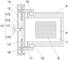
FIG. 1 is a schematic view of the present invention;
FIG. 2 is a top cross-sectional view of the case of the present invention;
fig. 3 is a bottom cross-sectional view of the traction assembly of the present invention.
In the figure: the device comprises a shell 1, supporting legs 2, heat exchange tubes 3, a box 4, an air inlet tube 5, an installation groove 6, a frame 7, a filter screen 8, an air outlet tube 9, an installation block 10, a sealing ring 11, an installation cavity 12, a threaded rod 13, a moving block 14, a positioning groove 15, a positioning block 16, a driving assembly 17, a rotating shaft 171, a driving bevel gear 172, a driven bevel gear 173, a hand wheel 174, a sliding groove 18, a sliding block 19, an installation tube 20, a nozzle 21, a connecting tube 22, a traction assembly 23, a driving motor 231, a rotary disc 232, a deflector rod 233 and a movable frame 234.
Detailed Description
The technical solutions in the embodiments of the present invention will be described clearly and completely with reference to the accompanying drawings in the embodiments of the present invention, and it is obvious that the described embodiments are only some embodiments of the present invention, not all embodiments. Based on the embodiments in the present invention, all other embodiments obtained by a person skilled in the art without creative work belong to the protection scope of the present invention.
Referring to fig. 1-3, the present invention provides a technical solution: the utility model provides an annealing kiln waste heat collection device, which comprises a housin 1, the equal fixed mounting in bottom left and right sides of casing 1 has quantity to be two supporting legs 2, casing 1's left side fixed mounting has one end to extend to its right side heat exchange tube 3, casing 1's top fixed mounting has box 4, box 4's top fixed mounting has one end to extend to its inside intake pipe 5, mounting groove 6 has been seted up on box 4's inner wall right side, movable mounting has one end to extend to its left side and the other end extends to the inside framework 7 of mounting groove 6 between the inner wall front and back both sides of box 4, the through-hole with framework 7 looks adaptation is seted up on box 4's inner wall left side, the inside fixed mounting of framework 7 has filter screen 8, casing 1's interior diapire fixed mounting has one end to extend to its bottom outlet duct 9.
A mounting block 10 is fixedly mounted on the left side of the frame body 7, a sealing ring 11 which is positioned on the outer side of the frame body 7 and one end of which is attached to the left side of the box body 4 is fixedly mounted on the right side of the mounting block 10, a mounting cavity 12 is formed in the mounting block 10, a threaded rod 13 is movably mounted between the front side and the rear side of the inner wall of the mounting cavity 12, bearings are fixedly mounted on the front side and the rear side of the inner wall of the mounting cavity 12, the threaded rod 13 is rotatably connected with the inner wall of the mounting cavity 12 through the bearings, the front end and the rear end of the outer side of the threaded rod 13 are respectively in threaded connection with a movable block 14, one end of which is movably connected with the left side of the inner wall of the mounting cavity 12, and the other end of which respectively extends to the front side and the rear side of the box body 4, threaded rod 13's the outside is provided with two sections screw threads and two sections equal opposite direction of screw length, the screw hole with threaded rod 13 looks adaptation is all seted up to the inside of two movable blocks 14, both ends all communicate around installation cavity 12 inner wall right side have set up on installation piece 10 and respectively with the rectangle strip hole of two movable blocks 14 moving trajectory looks adaptations, both sides swing joint about the upper and lower both sides of movable block 14 respectively with the inner wall in rectangle strip hole, constant head tank 15 has all been seted up to both sides around box 4, the equal fixed mounting in opposite side of two movable blocks 14 has one end to extend to two inside locating pieces 16 of constant head tank 15 respectively.
The outside fixed mounting of threaded rod 13 has one end to extend to the left drive assembly 17 of installation piece 10, drive assembly 17 includes pivot 171, the left side movable mounting of installation piece 10 has one end to extend to the inside pivot 171 of installation cavity 12, the inner wall left side intercommunication of installation cavity 12 has the mounting hole of seting up on installation piece 10 and with pivot 171 looks adaptation, the right side fixed mounting of pivot 171 has the drive bevel gear 172 that is located the threaded rod 13 left side and is located between two movable blocks 14, the outside fixed mounting of threaded rod 13 has the driven bevel gear 173 of one end and drive bevel gear 172 meshing, the left side fixed mounting of pivot 171 has hand wheel 174.
The top right side fixed mounting of casing 1 has one end to extend to its inside and with installation pipe 20 top fixed connection's traction assembly 23, traction assembly 23 includes driving motor 231, the top right side fixed mounting of casing 1 has driving motor 231, driving motor 231's model is Y355, driving motor 231's output shaft extends to inside and fixed mounting of casing 1 has the carousel 232 that is located the right side slider 19 right side and is located the installation pipe 20 top, the bottom fixed mounting of carousel 232 has driving lever 233, the top fixed mounting of installation pipe 20 has the removal frame 234 of cover in the driving lever 233 outside.
When the heat exchanger is used, hot air after glass cooling in an annealing kiln is injected into the box body 4 through the air inlet pipe 5, the filter screen 8 filters dust in the hot air, then the hot air enters the inside of the installation pipe 20 through the connecting pipe 22 and is sprayed out from the nozzle 21 to heat the heat exchange pipe 3, meanwhile, combustion-supporting air is introduced into the heat exchange pipe 3 to heat the combustion-supporting air, the driving motor 231 is started to drive the rotary disc 232 to rotate, the rotary disc 232 drives the installation pipe 20 to integrally move left and right in a reciprocating mode through the deflector rod 233 and the moving frame 234 in the rotating process, the nozzle 21 moves left and right, the air supply range is expanded, the hot air is uniformly distributed in the shell body 1, the hot air is in contact with the outer side of the heat exchange pipe 3 as much as possible to improve the heating effect of the heat exchange pipe 3, the efficiency of the heat exchange pipe is improved, the hot air after heat exchange is discharged through the air outlet pipe 9, when the heat exchange is required to be cleaned, the hand wheel 174 drives the hot air to drive the bevel gear to drive the positioning block 171 to move out of the bevel gear 13, the bevel gear 13 is pulled out of the mounting block 13, the bevel gear 13 is removed, and the positioning block 14 is removed from the box body 14, and the bevel gear 13 is removed from the box body 14.
In summary, the waste heat collecting device of the annealing kiln drives the rotating shaft 171 and the driving bevel gear 172 to rotate by screwing the hand wheel 174, the driven bevel gear 173 drives the threaded rod 13 to rotate, and the threaded rod 13 drives the two moving blocks 14 and the two positioning blocks 16 to move back to back in the rotating process until the two positioning blocks 16 are respectively moved out of the two positioning grooves 15, thereby releasing the position restriction of the mounting block 10, and at this time, the mounting block 10 is pulled leftward to draw out the frame body 7 from the inside of the case 4, thereby the filter screen 8 is disassembled, thereby realizing the purpose of conveniently disassembling the filter screen 8, thereby facilitating the cleaning of the filter screen 8, driving the rotary disc 232 to rotate by starting the driving motor 231, the rotating disc 232 drives the mounting tube 20 to move back and forth left and right through the driving rod 233 and the moving frame 234 during the rotation process, while the nozzle 21 can expand the air feeding range in the process of moving left and right, so that the hot air is uniformly distributed in the shell 1 and contacts with the outer side of the heat exchange tube 3 as much as possible, thereby improving the heating effect of the heat exchange tube 3, thereby improving the heat exchange efficiency, solving the problems that the prior annealing kiln waste heat collecting device has poor heat exchange efficiency, in order to avoid the dust in the air from adhering to the heat exchange tube and affecting the heat exchange effect, a filter screen is usually arranged to filter the air, as the filter screen is mostly arranged inside the air inlet pipe and is inconvenient to disassemble, the filter screen is inconvenient to clean, and the existing annealing kiln waste heat collecting device is easy to cause the condition of uneven distribution in the device in hot air in the using process, thus leading to the problems of poor heating effect and low heat exchange efficiency of the heat exchange pipe.
It is noted that, herein, relational terms such as first and second, and the like may be used solely to distinguish one entity or action from another entity or action without necessarily requiring or implying any actual such relationship or order between such entities or actions. Also, the terms "comprises," "comprising," or any other variation thereof, are intended to cover a non-exclusive inclusion, such that a process, method, article, or apparatus that comprises a list of elements does not include only those elements but may include other elements not expressly listed or inherent to such process, method, article, or apparatus. Without further limitation, an element defined by the phrases "comprising a," "8230," "8230," or "comprising" does not exclude the presence of additional like elements in a process, method, article, or apparatus that comprises the element.
Although embodiments of the present invention have been shown and described, it will be appreciated by those skilled in the art that changes, modifications, substitutions and alterations can be made in these embodiments without departing from the principles and spirit of the invention, the scope of which is defined in the appended claims and their equivalents.
Claims (6)
1. The utility model provides an annealing kiln waste heat collection device, includes casing (1), the bottom left and right sides of casing (1) all is provided with supporting legs (2) that quantity is two, the left side of casing (1) is provided with heat exchange tube (3) that one end extends to its right side, the top of casing (1) is provided with box (4), the top of box (4) is provided with one end and extends to its inside intake pipe (5), the inner wall right side of box (4) is provided with mounting groove (6), be provided with between the inner wall front and back both sides of box (4) one end and extend to its left side and the other end extends to the inside framework (7) of mounting groove (6), the inside of framework (7) is provided with filter screen (8), the inner diapire of casing (1) is provided with outlet duct (9) that one end extends to its bottom, its characterized in that: a mounting block (10) is arranged on the left side of the frame body (7), a sealing ring (11) which is positioned on the outer side of the frame body (7) and one end of which is attached to the left side of the box body (4) is arranged on the right side of the mounting block (10), a mounting cavity (12) is arranged inside the mounting block (10), a threaded rod (13) is arranged between the front side and the rear side of the inner wall of the mounting cavity (12), positioning grooves (15) are arranged on the front side and the rear side of the outer side of the threaded rod (13), one end of the positioning block (16) is movably connected with the left side of the inner wall of the mounting cavity (12), the other end of the positioning block extends to the front side and the rear side of the box body (4), positioning blocks (15) are arranged on the front side and the rear side of the box body (4), positioning blocks (16) are arranged on the opposite sides of the two moving blocks (14), a driving assembly (17) with one end extending to the left side of the mounting block (10) is arranged on the outer side of the threaded rod (13), sliding grooves (18) are arranged on the left side and right side of the inner top wall of the shell (1), a sliding block (19) is arranged on the front side and a nozzle (20) is arranged on the bottom of the left side of the bottom of the sliding block (19) and fixed pipe (19) which extends to the bottom of the mounting block (19), the inner bottom wall of box (4) is provided with one end and extends to inside connecting pipe (22) of installation pipe (20), the top right side of casing (1) is provided with one end and extends to its inside and with installation pipe (20) top fixed connection's traction assembly (23).
2. The annealing kiln waste heat collecting device according to claim 1, characterized in that: drive assembly (17) are including pivot (171), the left side movable mounting of installation piece (10) has pivot (171) that one end extends to installation cavity (12) inside, the right side fixed mounting of pivot (171) has drive bevel gear (172) that are located threaded rod (13) left side and are located between two movable blocks (14), the outside fixed mounting of threaded rod (13) has one end and drive bevel gear (172) engaged with driven bevel gear (173), the left side fixed mounting of pivot (171) has hand wheel (174).
3. The annealing kiln waste heat collecting device according to claim 1, characterized in that: traction assembly (23) includes driving motor (231), the top right side fixed mounting of casing (1) has driving motor (231), the output shaft of driving motor (231) extends to inside and fixed mounting of casing (1) has carousel (232) that are located right side slider (19) right side and are located installation pipe (20) top, the bottom fixed mounting of carousel (232) has driving lever (233), the top fixed mounting of installation pipe (20) has removal frame (234) of cover in driving lever (233) outside.
4. The annealing kiln waste heat collecting device according to claim 1, characterized in that: the equal fixed mounting in both sides has the bearing around the inner wall of installation cavity (12), threaded rod (13) are connected through the inner wall rotation of bearing and installation cavity (12).
5. The annealing kiln waste heat collecting device according to claim 1, characterized in that: two sections of threads are arranged on the outer side of the threaded rod (13), the lengths of the two sections of threads are equal, the directions of the two sections of threads are opposite, and threaded holes matched with the threaded rod (13) are formed in the two moving blocks (14).
6. The annealing kiln waste heat collecting device according to claim 1, characterized in that: the front end and the rear end of the right side of the inner wall of the mounting cavity (12) are communicated with rectangular strip holes which are formed in the mounting block (10) and are respectively matched with the moving tracks of the two moving blocks (14), and the upper side and the lower side of each moving block (14) are respectively movably connected with the upper side and the lower side of the inner wall of each rectangular strip hole.
Priority Applications (1)
| Application Number | Priority Date | Filing Date | Title |
|---|---|---|---|
| CN202222710441.3U CN218115285U (en) | 2022-10-14 | 2022-10-14 | Waste heat collecting device for annealing kiln |
Applications Claiming Priority (1)
| Application Number | Priority Date | Filing Date | Title |
|---|---|---|---|
| CN202222710441.3U CN218115285U (en) | 2022-10-14 | 2022-10-14 | Waste heat collecting device for annealing kiln |
Publications (1)
| Publication Number | Publication Date |
|---|---|
| CN218115285U true CN218115285U (en) | 2022-12-23 |
Family
ID=84498168
Family Applications (1)
| Application Number | Title | Priority Date | Filing Date |
|---|---|---|---|
| CN202222710441.3U Active CN218115285U (en) | 2022-10-14 | 2022-10-14 | Waste heat collecting device for annealing kiln |
Country Status (1)
| Country | Link |
|---|---|
| CN (1) | CN218115285U (en) |
Cited By (1)
| Publication number | Priority date | Publication date | Assignee | Title |
|---|---|---|---|---|
| CN116041045A (en) * | 2023-01-31 | 2023-05-02 | 宜兴爱宜艺术陶瓷有限公司 | Firing method of dark-red enameled pottery and kiln using same |
-
2022
- 2022-10-14 CN CN202222710441.3U patent/CN218115285U/en active Active
Cited By (2)
| Publication number | Priority date | Publication date | Assignee | Title |
|---|---|---|---|---|
| CN116041045A (en) * | 2023-01-31 | 2023-05-02 | 宜兴爱宜艺术陶瓷有限公司 | Firing method of dark-red enameled pottery and kiln using same |
| CN116041045B (en) * | 2023-01-31 | 2023-10-31 | 宜兴爱宜艺术陶瓷有限公司 | Firing method of dark-red enameled pottery and kiln using same |
Similar Documents
| Publication | Publication Date | Title |
|---|---|---|
| CN218115285U (en) | Waste heat collecting device for annealing kiln | |
| CN210773580U (en) | High-efficient waste heat recovery equipment in textile industry forming machine production line | |
| CN113686056A (en) | Automobile air conditioner condenser with cleaning and maintaining functions | |
| CN213472715U (en) | Effectual new energy automobile heat pump air conditioner defrosts | |
| CN112121605B (en) | Combined type cold and hot circulation drying device for industrial gas drying | |
| CN213956074U (en) | Novel gas cooler for compressor | |
| CN219868052U (en) | Lampblack purifier with cleaning function | |
| CN116147013B (en) | Circulating cooling water recovery device of steam turbine | |
| CN213746792U (en) | Organic waste gas treatment device for production of spraying material | |
| CN216175467U (en) | Flattening device for alloy steel strip processing | |
| CN212842307U (en) | Integrated frequency conversion module cold water machine | |
| CN211641398U (en) | Waste heat recovery device for printing production | |
| CN110274486B (en) | Cement kiln heat exchanger tube box | |
| CN219988235U (en) | Injection molding product cooling device | |
| CN112503820A (en) | Full-automatic industrial refrigerating machine convenient to clean | |
| CN2711538Y (en) | Spiral blade roller slag cooling machine | |
| CN220401159U (en) | Door catch type side plate for power distribution cabinet and power distribution cabinet | |
| CN212408695U (en) | Cinder cooling waste heat recovery utilizes device | |
| CN218955575U (en) | Refrigeration plant convenient to clearance blade | |
| CN220230145U (en) | Dry-wet combined evaporation air cooler defogging device | |
| CN218442980U (en) | Slag cooler device for carburant production | |
| CN114484861B (en) | Building heating device that leads to warmly | |
| CN220083785U (en) | Heat energy recovery mechanism of air compressor | |
| CN219454614U (en) | Pellet shaft furnace roasting device | |
| CN218938077U (en) | High low temperature test chamber is from cascade refrigeration structure |
Legal Events
| Date | Code | Title | Description |
|---|---|---|---|
| GR01 | Patent grant | ||
| GR01 | Patent grant |