CN218105251U - Connecting fastener and wardrobe with same - Google Patents
Connecting fastener and wardrobe with same Download PDFInfo
- Publication number
- CN218105251U CN218105251U CN202222359279.5U CN202222359279U CN218105251U CN 218105251 U CN218105251 U CN 218105251U CN 202222359279 U CN202222359279 U CN 202222359279U CN 218105251 U CN218105251 U CN 218105251U
- Authority
- CN
- China
- Prior art keywords
- buckle
- connecting buckle
- clothes hanger
- connector link
- fastener
- Prior art date
- Legal status (The legal status is an assumption and is not a legal conclusion. Google has not performed a legal analysis and makes no representation as to the accuracy of the status listed.)
- Active
Links
Images


Landscapes
- Holders For Apparel And Elements Relating To Apparel (AREA)
Abstract
The utility model discloses a connecting fastener, which comprises a first connecting buckle and a second connecting buckle, wherein a first mounting part is arranged at the first end of the first connecting buckle, and a first connecting part is arranged at the second end of the first connecting buckle; a first mounting part is arranged at the first end of the second connecting buckle, and a second connecting part is arranged at the second end of the second connecting buckle; first connecting portion and second connecting portion lock joint cooperation are in order can dismantle the spiral-lock as an organic whole with the second connecting link through first connecting portion and second connecting portion lock joint, adopt simple structure, lock joint convenience and connect reliable first connecting link and second connecting link, when this connection fastener is applied to lift clothes hanger, can make things convenient for the dismouting of backplate, have solved the dismouting backplate and need with the help of instrument and the inconvenient problem of dismouting.
Description
Technical Field
The utility model relates to a technical field of wardrobe, in particular to connect fastener and have wardrobe of this connection fastener.
Background
The wardrobe is also a kind of furniture, is a cabinet for storing and storing clothes, generally takes a cabinet body, a door panel and a door curtain as components, and is internally provided with a clothes hanging rod, a trousers rack, a pull basket and the like. The fixed clothes hanging rod is usually arranged inside the existing wardrobe, so that the wardrobe can not adapt to the use heights of different people, such as the old, children, the disabled and the like, and is inconvenient to use.
Therefore, technical personnel design a wardrobe with a liftable clothes hanging rod, for example, a chinese patent (publication No. CN 217243209U), which includes a wardrobe body and a lifting mechanism, wherein a storage space is provided inside the wardrobe body, a door panel facing the storage space is provided on the wardrobe body, the door panel is hinged to the wardrobe body, the lifting mechanism is installed on the inner wall of the wardrobe body, so that the lifting mechanism is disposed in the storage space for lifting, a laminate is provided at a lifting end of the lifting mechanism, the clothes hanging rod is hung at the bottom of the laminate, a back panel fixedly connected to the back of the wardrobe body through a fastening device is provided in the storage space, an accommodating cavity is formed between the back panel and the back of the wardrobe body, and the lifting mechanism is accommodated in the accommodating cavity, thereby playing a role in protection and beauty.
In above-mentioned wardrobe, the backplate is all around through the rear end fixed connection of fastener and clothes hanger main part for the dismouting of backplate is all comparatively loaded down with trivial details when installation in earlier stage and later stage maintenance elevating system, specifically in needing operating personnel to get into the storing space of wardrobe, because the limited dismouting that makes of space is comparatively inconvenient, on the other hand, the fastener that sets up at the backplate top is because highly higher, consequently need carry out the dismouting with the help of the fastener at top with the help of the instrument, consequently need design a section and be convenient for carry out the connection structure of dismouting to the backplate.
Disclosure of Invention
The utility model aims at providing a connect fastener and have wardrobe of this connection fastener, through setting up the dismouting that this connection fastener can be convenient for wardrobe backplate.
The above technical object of the present invention can be achieved by the following technical solutions: the first embodiment is as follows: a connecting fastener comprises a first connecting buckle and a second connecting buckle, wherein a first mounting part is arranged at the first end of the first connecting buckle, and a first connecting part is arranged at the second end of the first connecting buckle; a first mounting part is arranged at the first end of the second connecting buckle, and a second connecting part is arranged at the second end of the second connecting buckle; the first connecting buckle is matched with the second connecting buckle in a buckling mode through the first connecting part and the second connecting part, and can be detachably buckled into a whole with the second connecting buckle.
Furthermore, the first connecting portion is an elastic clamping pin, and the second connecting portion is a fastening groove matched with the elastic clamping pin in a fastening mode.
Furthermore, the second end of the second connecting buckle is provided with a guide inclined plane which is convenient for the elastic clamping foot to be clamped into the buckle groove.
Further, first connector link and second connector link all include the body and the symmetry sets up in the support arm of body both sides, first installation department and second installation department set up on the body that corresponds the connector link, first connecting portion are equipped with two sets of and symmetry and set up the two support arm tip at first connector link, second connecting portion are equipped with two sets of and symmetry and set up the two support arm tip at the second connector link.
Furthermore, the bodies of the first connecting buckle and the second connecting buckle are provided with connecting blocks, and two sides of each connecting block are connected to the support arms at two ends.
Furthermore, the first connecting buckle and the second connecting buckle are respectively provided with a weight reduction groove corresponding to the outer sides of the two support arms.
Furthermore, two sets of weight reduction grooves are respectively formed in the outer sides of the first connecting buckle and the second connecting buckle corresponding to the two support arms, so that three sets of reinforcing plate structures arranged at intervals are formed on the outer sides of the support arms.
Further, first installation department and second installation department are the pilot hole respectively, the pilot hole is equipped with two sets ofly and the symmetry sets up the both sides at the connecting block.
Furthermore, a notch is formed between the two support arms of the first connecting buckle and the second connecting buckle, so that the body and the two support arms form a U-shaped structure.
The utility model provides a wardrobe, includes clothes hanger body, backplate, elevating system and has embodiment one the connection fastener, the first installation department fixed connection of the first connector link of connection fastener is around the backplate, the second installation department fixed connection of second connector link is around clothes hanger body rear end, and the backplate is adorned in clothes hanger body rear end with removable knot through first connector link and second connector link lock joint cooperation, be formed with the holding chamber between clothes hanger body rear end and the backplate, elevating system sets up at holding intracavity and fixed connection in clothes hanger body rear end, and elevating system is equipped with the crossbeam of liftable, and the crossbeam both sides are equipped with the installation arm, the backplate is equipped with the groove of dodging that supplies the vertical lift of installation arm or is formed with between backplate and the clothes hanger body both sides and supplies the vertical lift of installation arm to dodge the groove, and fixed mounting has the plywood on two installation arms, and the lower extreme is equipped with hangs the clothing pole.
To sum up, the utility model discloses following beneficial effect has:
the utility model discloses a connect fastener, adopt simple structure, the lock joint is convenient and connect reliable first connector link and second connector link, when this connect fastener is applied to lift clothes hanger, can make things convenient for the dismouting of backplate, solved the dismouting backplate and need with the help of instrument and the inconvenient problem of dismouting, specifically, the first installation department fixed connection of first connector link is around the backplate, the second installation department fixed connection of second connector link is around clothes hanger body rear end, the backplate is through first connector link and the cooperation of second connector link lock joint in clothes hanger body rear end with removable lock joint.
Drawings
Fig. 1 is a schematic structural view of the first connecting buckle and the second connecting buckle of the present invention.
Fig. 2 is a top view of the first and second connecting buckles of the present invention.
Fig. 3 is a schematic view of the hanger of the present invention.
Fig. 4 is a schematic structural diagram of the lifting mechanism of the present invention.
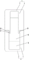
Figure 5 is a front schematic view of the hanger body of the present invention.
In the figure: 1. a first connecting buckle; 11. a first mounting portion; 12. a first connection portion; 2. a second connecting buckle; 21. a second mounting portion; 22. a second connecting portion; 23. a guide slope; 3. a body; 31. connecting blocks; 4. a support arm; 41. a weight reduction groove; 42. a recess; 5. a hanger body; 6. a back plate; 7. a lifting mechanism; 71. a cross beam; 72. a mounting arm; 8. laminating the board; 81. a clothes rail.
Detailed Description
The present invention will be further described with reference to the accompanying drawings.
As shown in fig. 1-5, in the first embodiment: a connecting fastener comprises a first connecting buckle 1 and a second connecting buckle 2, wherein a first mounting part 11 is arranged at a first end of the first connecting buckle 1, and a first connecting part 12 is arranged at a second end of the first connecting buckle 1; a first end of the second connecting buckle 2 is provided with a second mounting part 21, and a second end of the second connecting buckle 2 is provided with a second connecting part 22; first connector link 1 is as an organic whole through first connecting portion 12 and the cooperation of second connecting portion 22 lock joint in order to detain with second connector link 2, specifically, first connecting portion 12 is elasticity card foot, second connecting portion 22 be with elasticity card foot lock joint complex catching groove, certainly as equivalent substitute means, can set up second connecting portion 22 into elasticity card foot, first connecting portion 12 be with elasticity card foot lock joint complex catching groove, the utility model discloses a first connector link 1 and second connector link 2 simple structure, lock joint convenience and connection are reliable.
The second end of second connector link 2 is equipped with the direction inclined plane 23 that the slot was gone into to the elasticity card foot card of being convenient for, and this setting makes first connector link 1 and second connector link 2 more smooth and easy when spiral-lock.
Be equipped with connecting block 31 on the body 3 of first connector link 1 and second connector link 2, the support arm 4 at both ends is connected to the both sides of connecting block 31, makes first connector link 1 and second connector link 2's intensity higher through setting up connecting block 31, first installation department 11 and second installation department 21 are the pilot hole respectively, the pilot hole is equipped with two sets ofly and the symmetry sets up the both sides at connecting block 31.
The outer sides of the two support arms 4 corresponding to the first connecting buckle 1 and the second connecting buckle 2 are respectively provided with a weight reducing groove 41, materials of the first connecting buckle 1 and the second connecting buckle 2 can be saved by arranging the weight reducing grooves 41, the overall mass of the connecting buckle can be reduced, the outer sides of the two support arms 4 corresponding to the first connecting buckle 1 and the second connecting buckle 2 are respectively provided with two groups of weight reducing grooves 41, so that the outer sides of the support arms 4 form three groups of reinforcing plate structures arranged at intervals, and the strength of the first connecting buckle 1 and the strength of the second connecting buckle 2 can be greatly improved by the arrangement.
A wardrobe comprises a clothes hanger body 5, a back plate 6, a lifting mechanism 7 and a connecting fastener as described in the first embodiment, wherein a first mounting part 11 of a first connecting fastener 1 of the connecting fastener is fixedly connected to the periphery of the back plate 6, a second mounting part 21 of a second connecting fastener 2 is fixedly connected to the periphery of the rear end of the clothes hanger body 5, the back plate 6 is mounted at the rear end of the clothes hanger body 5 in a detachable way through the buckling and matching of the first connecting fastener 1 and the second connecting fastener 2, a containing cavity is formed between the rear end of the clothes hanger body 5 and the back plate 6, the lifting mechanism 7 is arranged in the accommodating cavity and fixedly connected to the rear end of the clothes hanger body 5, the lifting mechanism 7 is provided with a lead screw assembly and a lifting beam 71, mounting arms 72 are arranged on two sides of the beam 71, the back plate 6 is provided with an avoiding groove for vertical lifting of the mounting arms 72 or an avoiding groove for vertical lifting of the mounting arms 72 is formed between the back plate 6 and two sides of the clothes hanger body 5, the two mounting arms 72 are fixedly provided with laminated plates 8, the lower ends of the laminated plates 8 are provided with clothes hanging rods 81, the lifting mechanism 7 drives the beam 71 to vertically lift, and the mounting arms 72, the laminated plates 8 and the clothes hanging rods 81 synchronously vertically lift along with the beam 71.
The utility model discloses a when connecting fastener is applied to lift clothes hanger, can make things convenient for the dismouting of backplate 6, solved dismouting backplate 6 and need with the help of the inconvenient problem of instrument and dismouting, specifically, 11 fixed connection in first installation department of first connector link 1 around backplate 6, second installation department 21 fixed connection of second connector link 2 is around 5 rear ends of clothes hanger body, backplate 6 through first connector link 1 and 2 lock joint cooperations of second connector link in 5 rear ends of clothes hanger body with removable lock joint.
What has just been said above is the preferred embodiment of the present invention, so all according to the utility model discloses a patent application scope structure, characteristic and principle do equivalent change or modify, all include the utility model discloses a patent application scope.
Claims (10)
1. A connecting fastener, characterized in that: comprises a first connecting buckle (1) and a second connecting buckle (2),
a first mounting part (11) is arranged at the first end of the first connecting buckle (1), and a first connecting part (12) is arranged at the second end of the first connecting buckle (1);
a second mounting part (21) is arranged at the first end of the second connecting buckle (2), and a second connecting part (22) is arranged at the second end of the second connecting buckle (2);
the first connecting buckle (1) is matched with the second connecting part (22) in a buckling mode through the first connecting part (12) to be detachably buckled with the second connecting buckle (2) into a whole.
2. A connecting fastener as claimed in claim 1, wherein: the first connecting portion (12) is an elastic clamping pin, and the second connecting portion (22) is a buckling groove matched with the elastic clamping pin in a buckling mode.
3. A connecting clip according to claim 2, wherein: the second end of the second connecting buckle (2) is provided with a guide inclined plane (23) which is convenient for the elastic clamping pin to be clamped into the buckle groove.
4. A connecting fastener as claimed in claim 1, wherein: first connector link (1) and second connector link (2) all include body (3) and symmetry set up in support arm (4) of body (3) both sides, first installation department (11) and second installation department (21) set up on body (3) that correspond the connector link, first connecting portion (12) are equipped with two sets of and symmetry and set up two support arm (4) tip in first connector link (1), second connecting portion (22) are equipped with two sets of and symmetry and set up two support arm (4) tip in second connector link (2).
5. A connecting clip according to claim 4, in which: the connecting block (31) is arranged on the body (3) of the first connecting buckle (1) and the second connecting buckle (2), and two sides of the connecting block (31) are connected to the support arms (4) at two ends.
6. A connecting clip according to claim 4, in which: the first connecting buckle (1) and the second connecting buckle (2) are respectively provided with a weight reduction groove (41) corresponding to the outer sides of the two support arms (4).
7. A connecting clip according to claim 6, wherein: two groups of weight reduction grooves (41) are respectively formed in the outer sides of the first connecting buckle (1) and the second connecting buckle (2) corresponding to the two support arms (4), so that three groups of reinforcing plate structures arranged at intervals are formed on the outer sides of the support arms (4).
8. A connecting clip according to claim 5, wherein: first installation department (11) and second installation department (21) are the pilot hole respectively, the pilot hole is equipped with two sets ofly and the symmetry sets up the both sides at connecting block (31).
9. A connecting clip according to claim 4, in which: a notch (42) is formed between the two support arms (4) of the first connecting buckle (1) and the second connecting buckle (2), so that the body (3) and the two support arms (4) form a U-shaped structure.
10. A wardrobe is characterized in that: the clothes hanger comprises a clothes hanger body (5), a back plate (6), a lifting mechanism (7) and the connecting fastener of any one of claims 1 to 9, wherein a first mounting portion (11) of a first connecting buckle (1) of the connecting fastener is fixedly connected to the periphery of the back plate (6), a second mounting portion (21) of a second connecting buckle (2) is fixedly connected to the periphery of the rear end of the clothes hanger body (5), the back plate (6) is detachably buckled and matched to the rear end of the clothes hanger body (5) through the first connecting buckle (1) and the second connecting buckle (2), a containing cavity is formed between the rear end of the clothes hanger body (5) and the back plate (6), the lifting mechanism (7) is arranged in the containing cavity and is fixedly connected to the rear end of the clothes hanger body (5), a liftable cross beam (71) is arranged on the lifting mechanism (7), mounting arms (72) are arranged on two sides of the cross beam (71), a avoiding groove for vertical lifting of the mounting arms (72) is formed between the back plate (6) and the clothes hanger body (5), and two vertical mounting grooves (8) for the mounting of the hanging arms (72) are arranged on the two sides, and two hanging plates (8) are arranged on the lifting mechanism.
Priority Applications (1)
| Application Number | Priority Date | Filing Date | Title |
|---|---|---|---|
| CN202222359279.5U CN218105251U (en) | 2022-09-06 | 2022-09-06 | Connecting fastener and wardrobe with same |
Applications Claiming Priority (1)
| Application Number | Priority Date | Filing Date | Title |
|---|---|---|---|
| CN202222359279.5U CN218105251U (en) | 2022-09-06 | 2022-09-06 | Connecting fastener and wardrobe with same |
Publications (1)
| Publication Number | Publication Date |
|---|---|
| CN218105251U true CN218105251U (en) | 2022-12-23 |
Family
ID=84528739
Family Applications (1)
| Application Number | Title | Priority Date | Filing Date |
|---|---|---|---|
| CN202222359279.5U Active CN218105251U (en) | 2022-09-06 | 2022-09-06 | Connecting fastener and wardrobe with same |
Country Status (1)
| Country | Link |
|---|---|
| CN (1) | CN218105251U (en) |
-
2022
- 2022-09-06 CN CN202222359279.5U patent/CN218105251U/en active Active
Similar Documents
| Publication | Publication Date | Title |
|---|---|---|
| US10323412B2 (en) | Wall-mount system for hanging modules | |
| CN218105251U (en) | Connecting fastener and wardrobe with same | |
| CN206630296U (en) | Novel easily install and remove drawer | |
| CN106247129B (en) | Hanger device and mounting method thereof | |
| CN213909141U (en) | Assembled wardrobe convenient to installation | |
| CN213282185U (en) | Multifunctional integrated trousers drawer and cabinet body | |
| CN220512605U (en) | Shoe rack with safety | |
| CN215077369U (en) | Clothes, hat, room and trousers rack | |
| CN221285017U (en) | Clothes hanger convenient to dismouting | |
| CN217090273U (en) | Hanging plate structure | |
| CN205758095U (en) | A kind of connector on combination sideboard | |
| CN217419064U (en) | Hidden electric clothes hanger | |
| CN216021854U (en) | Medical platform of jib formula and medical tower crane | |
| CN218304252U (en) | Novel stand of detachable goods shelf | |
| CN215993765U (en) | Frame structure of shower room and shower room with same | |
| CN220423450U (en) | Assembled combined wardrobe | |
| CN213282045U (en) | Quick detachable equipment's cupboard | |
| CN217301144U (en) | Cross-brace connecting rod capable of being installed quickly | |
| CN219594274U (en) | Open type multifunctional clothes hanger | |
| CN211408113U (en) | Titanium-plated stainless steel combined wardrobe convenient to install | |
| CN215382322U (en) | Wardrobe with high fixation performance | |
| CN220069126U (en) | Table frame structure | |
| CN212878422U (en) | Screen type storage rack | |
| CN207744866U (en) | Medical movable support cabinet | |
| CN219920579U (en) | Optimize mounting structure's customization cabinet |
Legal Events
| Date | Code | Title | Description |
|---|---|---|---|
| GR01 | Patent grant | ||
| GR01 | Patent grant |