CN218103023U - Roof photovoltaic installing support - Google Patents
Roof photovoltaic installing support Download PDFInfo
- Publication number
- CN218103023U CN218103023U CN202221928386.9U CN202221928386U CN218103023U CN 218103023 U CN218103023 U CN 218103023U CN 202221928386 U CN202221928386 U CN 202221928386U CN 218103023 U CN218103023 U CN 218103023U
- Authority
- CN
- China
- Prior art keywords
- platform
- elevating platform
- photovoltaic
- containing box
- department
- Prior art date
- Legal status (The legal status is an assumption and is not a legal conclusion. Google has not performed a legal analysis and makes no representation as to the accuracy of the status listed.)
- Active
Links
Images


Classifications
-
- Y—GENERAL TAGGING OF NEW TECHNOLOGICAL DEVELOPMENTS; GENERAL TAGGING OF CROSS-SECTIONAL TECHNOLOGIES SPANNING OVER SEVERAL SECTIONS OF THE IPC; TECHNICAL SUBJECTS COVERED BY FORMER USPC CROSS-REFERENCE ART COLLECTIONS [XRACs] AND DIGESTS
- Y02—TECHNOLOGIES OR APPLICATIONS FOR MITIGATION OR ADAPTATION AGAINST CLIMATE CHANGE
- Y02B—CLIMATE CHANGE MITIGATION TECHNOLOGIES RELATED TO BUILDINGS, e.g. HOUSING, HOUSE APPLIANCES OR RELATED END-USER APPLICATIONS
- Y02B10/00—Integration of renewable energy sources in buildings
- Y02B10/10—Photovoltaic [PV]
-
- Y—GENERAL TAGGING OF NEW TECHNOLOGICAL DEVELOPMENTS; GENERAL TAGGING OF CROSS-SECTIONAL TECHNOLOGIES SPANNING OVER SEVERAL SECTIONS OF THE IPC; TECHNICAL SUBJECTS COVERED BY FORMER USPC CROSS-REFERENCE ART COLLECTIONS [XRACs] AND DIGESTS
- Y02—TECHNOLOGIES OR APPLICATIONS FOR MITIGATION OR ADAPTATION AGAINST CLIMATE CHANGE
- Y02E—REDUCTION OF GREENHOUSE GAS [GHG] EMISSIONS, RELATED TO ENERGY GENERATION, TRANSMISSION OR DISTRIBUTION
- Y02E10/00—Energy generation through renewable energy sources
- Y02E10/50—Photovoltaic [PV] energy
Abstract
The utility model relates to a roof photovoltaic installing support, including base, containing box, elevating platform and photovoltaic board, the containing box sets up the upper surface department at the base, the elevating platform activity sets up the inside at the containing box, the top department of elevating platform is provided with the photovoltaic board, the diapire is close to center department and is provided with the telescopic link in the containing box, the top of telescopic link is connected with the lower surface of elevating platform, it is provided with and places the platform to rotate on the elevating platform, it is provided with the tooth to place the platform side, photovoltaic board lower extreme articulates the upper surface of placing the platform, the bracing piece has been passed in the activity in the through-hole of elevating platform left and right sides outer wall, two the one end that the bracing piece was kept away from each other is provided with the clamp splice respectively, reciprocates in the containing box through the elevating platform, can accomodate the photovoltaic board on the elevating platform into the containing box, can effectively protect the photovoltaic board when removing or changing the position, make it be difficult for receiving the collision of external object and lead to the emergence damage, improved the security.
Description
Technical Field
The application relates to a photovoltaic installing support construction technical field especially relates to a roof photovoltaic installing support.
Background
The photovoltaic power generation is a technology for directly converting light energy into electric energy by utilizing a photovoltaic effect of a semiconductor interface, mainly comprises three parts, namely a solar panel (assembly), a controller and an inverter, and mainly comprises electronic components, solar cells are connected in series and then packaged and protected to form a large-area solar cell assembly, and then are matched with components such as a power controller to form a photovoltaic power generation device, and a photovoltaic mounting bracket is usually used for supporting the photovoltaic power generation device;
roof photovoltaic installing support among the prior art, with the photovoltaic board through a plurality of bolt fastening on the installing support, because do not have better protection device, when the photovoltaic board need remove or change the position, receive the collision of object around and take place to damage easily, inconvenient protects the photovoltaic board, has reduced the security, consequently awaits improving.
SUMMERY OF THE UTILITY MODEL
In order to solve the problems presented in the background art, the present application provides a roof photovoltaic mounting bracket.
The application provides a roof photovoltaic installing support adopts following technical scheme:
the utility model provides a roof photovoltaic installing support, includes base, containing box, elevating platform and photovoltaic board, the containing box sets up the upper surface department at the base, the elevating platform activity sets up the inside at the containing box, the top department of elevating platform is provided with the photovoltaic board, the bottom wall is close to center department and is provided with the telescopic link in the containing box, the top of telescopic link is connected with the lower surface of elevating platform, it is provided with places the platform to rotate on the elevating platform, it is provided with the tooth to place the platform side, photovoltaic board lower extreme articulates the upper surface of placing the platform, the activity has passed the bracing piece in the through-hole of elevating platform left and right sides outer wall, two the one end that the bracing piece was kept away from each other is provided with the clamp splice respectively.
Through adopting above-mentioned technical scheme, utilize the telescopic link to drive the elevating platform and reciprocate in the containing box, can be convenient accomodate the photovoltaic board on the elevating platform into the containing box in, can remove or change the position effectively protect the photovoltaic board, make its collision that is difficult for receiving external object lead to taking place to damage, improved the security.
Preferably, the left side wall and the right side wall of the front side face of the lifting platform are provided with threaded rods in a rotating mode, the middle of each threaded rod is sleeved with a rotating sleeve, the threaded rods are provided with sliding sleeves and two moving rods close to two ends of each sliding sleeve, the outer walls of the front side face and the rear side face of the lifting platform are provided with through grooves, the two moving rods are movably inserted into the through grooves, and the two ends, far away from the clamping blocks, of the supporting rods are connected with the two moving rods respectively.
Through adopting above-mentioned technical scheme, change the cover and drive the threaded rod when rotating, utilize the removal of sliding sleeve on the threaded rod, drive two carriage release levers and remove in leading to the inslot, then drive the clamp splice of two bracing piece one ends and press from both sides tightly to the outer wall of containing box on, carry out spacing fixed to the elevating platform, improved the convenience.
Preferably, slide bars are arranged on the left side wall and the right side wall of the rear side face of the lifting platform, and one ends, far away from the threaded rod, of the two moving rods are movably sleeved on the slide bars.
Through adopting above-mentioned technical scheme, two movable rods slide on the slide bar, can play spacing effect to two movable rods for two movable rods move about in the elevating platform smoothly.
Preferably, it is provided with the pillar to place the platform upper surface, it is provided with the screw thread post to slide in the pillar, the top of screw thread post articulates the lower surface at the photovoltaic board and is close to upper end department, the one end that the screw thread post was inserted in the pillar is provided with the limiting plate, the cover has the disc on the part that the screw thread post is located the pillar upper surface, the disc bottom is connected with the rolling disc, the rotation groove has been seted up to the pillar upper surface, the rolling disc rotates and sets up in rotating the groove.
Through adopting above-mentioned technical scheme, the carousel rotates, can drive the rolling disc of its bottom and rotate in rotating the groove, makes the screw thread post can reciprocate in the pillar, and the upper end that the screw thread post drove the photovoltaic board reciprocates on placing the bench, and then realizes the adjustment to photovoltaic board inclination, makes its better absorption sunshine, improves the generating efficiency.
Preferably, the sliding grooves are formed in two sides of the inner wall of the strut, the sliding blocks are arranged on two sides of the limiting plate, and the sliding blocks are arranged in the two sliding grooves in a sliding mode respectively.
Through adopting above-mentioned technical scheme, utilize the slip of slider in the spout, can carry out spacingly to reciprocating of limiting plate, make the screw thread post realize vertical slip.
Preferably, the elevating platform upper surface is provided with the fixed block near the position department of placing the platform, the activity is provided with the movable rod in leading to the inslot on the fixed block, one side that the movable rod is close to placing the platform is provided with the arc, the tooth's socket has been seted up to one side that the movable rod was kept away from to the arc, it is connected to place to mesh between the tooth of platform side and the tooth's socket on the movable rod, the one end that the fixed block was worn out to the movable rod is provided with the fixed plate.
Through adopting above-mentioned technical scheme, the fixed plate of outside pulling movable rod one end makes the tooth's socket on the arc and the tooth that places the platform side take place to break away from, can rotate and place the platform, adjusts the position of photovoltaic board, has improved the practicality.
Preferably, the movable rod is sleeved with a spring, and two ends of the spring are connected to the arc-shaped plate and the fixed block respectively.
Through adopting above-mentioned technical scheme, under the elasticity effect of spring, place the tooth on the platform and inlay the tooth's socket on the arc, play fixed effect to placing the platform, prevent that it from taking place the rotation.
To sum up, the application comprises the following beneficial technical effects:
1. the utility model discloses a be provided with the containing box on the base, be provided with the telescopic link in the containing box, the telescopic link top is connected with the elevating platform, rotates on the elevating platform and is provided with and places the platform, places the bench and articulates there is the photovoltaic board, reciprocates in the containing box through the elevating platform, can accomodate the photovoltaic board on the elevating platform into the containing box, can effectively protect the photovoltaic board when removing or changing the position, makes it be difficult for receiving the collision of external object and leads to taking place the damage, has improved the security;
2. a threaded column is movably inserted into the support column, one end of the threaded column, penetrating out of the upper surface of the support column, is hinged with the upper end of the photovoltaic panel, a disc is sleeved on the part of the threaded column, positioned on the upper surface of the support column, a rotating disc is arranged at the bottom of the disc and is rotatably arranged in a rotating groove formed in the upper surface of the support column, the rotating disc at the bottom end of the rotating disc can be driven to rotate in the rotating groove by rotating the disc, so that the threaded column can move up and down in the support column, the threaded column drives the photovoltaic panel hinged at the top end of the threaded column to move up and down, and the inclination angle of the photovoltaic panel is adjusted to better absorb sunlight;
3. the elevating platform upper surface is close to the position department of placing the platform and is provided with the fixed block, and the movable rod has been inserted in the activity of fixed block, and movable rod one end is provided with the arc, and the tooth's socket of seting up on the arc is connected with the tooth of placing the side of the platform between the tooth, through outwards pulling the movable rod, makes tooth's socket on the arc and the tooth of placing the side of the platform take place to break away from, can rotate and place the platform, adjusts the photovoltaic board position, has improved the practicality.
Drawings
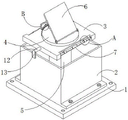
FIG. 1 is a schematic structural view of a rooftop photovoltaic mounting bracket according to an embodiment of the present disclosure;
FIG. 2 is a cross-sectional view of a structure at a rooftop photovoltaic mounting bracket post and threaded post in an embodiment of the present application;
FIG. 3 is a top view of a rooftop photovoltaic mounting bracket mounting deck according to an embodiment of the subject application;
FIG. 4 is an enlarged view of a structure at A in FIG. 1 of a rooftop photovoltaic mounting bracket according to an embodiment of the present disclosure;
fig. 5 is an enlarged view of a structure at B in fig. 1 of a roof photovoltaic mounting bracket according to an embodiment of the present application.
Description of the reference numerals: 1. a base; 2. a storage box; 3. a lifting platform; 4. a placing table; 5. a telescopic rod; 6. a photovoltaic panel; 7. rotating the sleeve; 8. a threaded rod; 9. a sliding sleeve; 10. a travel bar; 11. a slide bar; 12. a support bar; 13. a clamping block; 14. a fixed block; 15. a movable rod; 16. a spring; 17. an arc-shaped plate; 18. a support post; 19. a threaded post; 20. a disc; 21. rotating the disc; 22. a rotating groove; 23. a limiting plate; 24. a slider; 25. a chute.
Detailed Description
The present application is described in further detail below with reference to figures 1-5.
The embodiment of the application discloses roof photovoltaic installing support. Referring to fig. 1-5, a roof photovoltaic mounting bracket comprises a base 1, a storage box 2, a lifting platform 3 and a photovoltaic panel 6, wherein the storage box 2 is arranged on the upper surface of the base 1, the lifting platform 3 is movably arranged inside the storage box 2, the photovoltaic panel 6 is arranged above the lifting platform 3, a telescopic rod 5 is arranged on the inner bottom wall of the storage box 2 near the center, the top end of the telescopic rod 5 is connected with the lower surface of the lifting platform 3, a placing platform 4 is rotatably arranged on a rotating bearing on the lifting platform 3, teeth are arranged on the side surface of the placing platform 4, the lower end of the photovoltaic panel 6 is hinged on the upper surface of the placing platform 4, supporting rods 12 movably pass through holes on the outer walls of the left side and the right side of the lifting platform 3, clamping blocks 13 are respectively arranged at the ends of the two supporting rods 12, the lifting platform 3 is driven by the telescopic rod 5 to move up and down in the storage box 2, the photovoltaic panel 6 on the lifting platform 3 can be conveniently stored in the storage box 2, the photovoltaic panel 6 can be effectively protected when the lifting platform is moved or replaced, so that the photovoltaic panel is not easy to be damaged due to collision of external objects, the safety is improved, threaded rods 8 are rotatably arranged in rotating bearings on the left side wall and the right side wall of the front side surface of the lifting platform 3, threads on two sides of each threaded rod 8 are opposite, a rotating sleeve 7 is fixedly sleeved in the middle of each threaded rod 8, sliding sleeves 9 are respectively sleeved at two ends of each threaded rod 8, the inner wall of each sliding sleeve 9 is provided with a thread matched with the threaded rod 8, moving rods 10 are respectively arranged on the side surfaces of the two sliding sleeves 9, through grooves are formed in the outer walls of the front side surface and the rear side surface of the lifting platform 3, the two moving rods 10 are movably inserted into the through grooves, one ends of the two supporting rods 12, far away from a clamping block 13, are respectively connected with the two moving rods 10, the rotating sleeve 7 drives the threaded rods 8 to move on the threaded rods 8 by virtue of the sliding sleeves 9 when the rotating bearings are rotated, drive two carriage release levers 10 and remove in logical inslot, then the clamp splice 13 that drives two bracing pieces 12 one end presss from both sides tightly to the outer wall of containing box 2, carry on spacing fixed to elevating platform 3, the convenience is improved, be provided with slide bar 11 on the lateral wall about 3 trailing flanks of elevating platform, the equal movable sleeve of one end that threaded rod 8 was kept away from to two carriage release levers 10 is on slide bar 11, the through-hole that slide bar 11 passed has all been seted up on two carriage release levers 10, two carriage release levers 10 slide on slide bar 11, can play spacing effect to two carriage release levers 10, make two carriage release levers 10 smooth about in elevating platform 3.
Referring to fig. 1, 2 and 5, a support column 18 is arranged on the upper surface of the placing table 4, a threaded column 19 is slidably arranged in the support column 18, the top end of the threaded column 19 is hinged to the lower surface of the photovoltaic panel 6 near the upper end, a limit plate 23 is arranged at one end of the threaded column 19 inserted into the support column 18, a disc 20 is sleeved on the part of the threaded column 19 on the upper surface of the support column 18, a threaded hole matched with the threaded column 19 is formed in the disc 20, a rotating disc 21 is fixedly connected to the bottom of the disc 20, a rotating groove 22 is formed in the upper surface of the support column 18, the rotating disc 21 is rotatably arranged in the rotating groove 22, the cross sections of the rotating disc 21 and the rotating groove 22 are both in a "T" shape, the rotating disc 20 can drive the rotating disc 21 at the bottom end to rotate in the rotating groove 22, so that the threaded column 19 can move up and down in the support column 18, the threaded column 19 drives the upper end of the photovoltaic panel 6 to move up and down on the placing table 4, thereby realizing the adjustment of the inclination angle of the photovoltaic panel 6, leading the photovoltaic panel to better absorb sunlight and improving the power generation efficiency, both sides of the inner wall of the pillar 18 are provided with sliding grooves 25, both sides of the limiting plate 23 are provided with sliding blocks 24, the two sliding blocks 24 are respectively arranged in the two sliding grooves 25 in a sliding way, the up-and-down movement of the limiting plate 23 can be limited by the sliding of the sliding blocks 24 in the sliding grooves 25, leading the threaded column 19 to realize vertical sliding, the upper surface of the lifting platform 3 near the placing platform 4 is provided with a fixed block 14, a movable rod 15 is movably arranged in the through groove on the fixed block 14, one side of the movable rod 15 near the placing platform 4 is provided with an arc-shaped plate 17, one side of the arc-shaped plate 17 far away from the movable rod 15 is provided with a tooth groove, the tooth on the side of the placing platform 4 is engaged and connected with the tooth groove on the movable rod 15, one end of the movable rod 15 penetrating through the fixed block 14 is provided with a fixed plate, and the fixed plate at one end of the movable rod 15 is pulled outwards, make tooth's socket on the arc 17 and place the tooth of 4 sides of platform and take place to break away from, can rotate and place platform 4, adjust the position of photovoltaic board 6, improved the practicality, the cover has spring 16 on the movable rod 15, spring 16's both ends are connected respectively on arc 17 and fixed block 14, under spring 16's elastic force effect, place the tooth on the platform 4 and inlay in the tooth's socket on the arc 17, play fixed effect to placing platform 4, prevent that it from taking place the rotation.
The implementation principle of this application embodiment roof photovoltaic installing support does: firstly, the bracket is installed on a roof through an expansion screw, the lifting platform 3 is moved out of the containing box 2, the rotating sleeve 7 at the front side of the lifting platform 3 is rotated, the threaded rod 8 is driven to rotate through the rotating sleeve 7, the two moving rods 10 are driven to slide on the sliding rods 11 by utilizing the movement of the sliding sleeve 9 on the threaded rod 8, then the two supporting rods 12 are driven to mutually approach at two sides of the lifting platform 3, the clamping blocks 13 at two sides are clamped on the outer wall of the containing box 2, the lifting platform 3 is limited and fixed, when the inclination angle of the photovoltaic plate 6 needs to be adjusted, the disc 20 above the supporting column 18 is rotated, the rotating disc 21 at the bottom end of the rotating disc can be driven to rotate in the rotating groove 22, the threaded column 19 can move up and down in the supporting column 18, the threaded column 19 drives the photovoltaic plate 6 hinged at the top end of the photovoltaic plate to move up and down, the inclination angle of the photovoltaic plate 6 can be adjusted, sunlight can be better absorbed, the fixed plate at one side of the fixed block 14 is pulled outwards, the moving rod 15 is driven to move outwards, the toothed groove on the arc-shaped plate 17 is separated from the teeth at the side of the placing platform 4, the tooth groove, the fixed plate can be adjusted, the elastic spring is adjusted, the elastic plate, the elastic spring is prevented from being loosened, and the fixed plate, and the elastic spring is strong in effect of the simple elastic fixture plate 17, and is realized, and the fixing plate, the elastic spring is realized.
The above are preferred embodiments of the present application, and the scope of protection of the present application is not limited thereto, so: all equivalent changes made according to the structure, shape and principle of the present application shall be covered by the protection scope of the present application.
Claims (7)
1. The utility model provides a roof photovoltaic installing support, includes base (1), containing box (2), elevating platform (3) and photovoltaic board (6), containing box (2) set up the upper surface department at base (1), elevating platform (3) activity sets up the inside at containing box (2), the top department of elevating platform (3) is provided with photovoltaic board (6), its characterized in that: the utility model discloses a photovoltaic solar energy collecting box, including containing box (2), the top of telescopic link (5) is connected with the lower surface of elevating platform (3), it is provided with and places platform (4) to rotate on elevating platform (3), it is provided with tooth to place platform (4) side, photovoltaic board (6) lower extreme articulates the upper surface of placing platform (4), the activity has passed bracing piece (12), two in the through-hole of elevating platform (3) left and right sides outer wall the one end of keeping away from each other of bracing piece (12) is provided with clamp splice (13) respectively.
2. The rooftop photovoltaic mounting rack of claim 1, wherein: the utility model discloses a lifter, including elevating platform (3), threaded rod (8) are provided with in the rotation on the lateral wall about elevating platform (3) leading flank, the middle department cover of threaded rod (8) has a commentaries on classics cover (7), threaded rod (8) are close to both ends department and all overlap there are sliding sleeve (9), two sliding sleeve (9)'s side all is provided with carriage release lever (10), logical groove has been seted up on the side outer wall around elevating platform (3) on the equal activity of carriage release lever (10) inserts logical groove, two the one end that clamp splice (13) was kept away from in bracing piece (12) is connected with two carriage release levers (10) respectively.
3. The rooftop photovoltaic mounting bracket of claim 2, wherein: slide bars (11) are arranged on the left side wall and the right side wall of the rear side face of the lifting platform (3), and one ends, far away from the threaded rods (8), of the moving rods (10) are movably sleeved on the slide bars (11).
4. The rooftop photovoltaic mounting bracket of claim 1, wherein: place platform (4) upper surface and be provided with pillar (18), it is provided with screw thread post (19) to slide in pillar (18), the top of screw thread post (19) articulates the lower surface at photovoltaic board (6) and is close to upper end department, the one end that screw thread post (19) inserted in pillar (18) is provided with limiting plate (23), the cover has disc (20) on the part that screw thread post (19) are located pillar (18) upper surface, disc (20) bottom is connected with rolling disc (21), rotation groove (22) have been seted up to pillar (18) upper surface, rolling disc (21) rotate and set up in rotation groove (22).
5. The rooftop photovoltaic mounting bracket of claim 4, wherein: sliding grooves (25) are formed in two sides of the inner wall of the support column (18), sliding blocks (24) are arranged on two sides of the limiting plate (23), and the two sliding blocks (24) are arranged in the two sliding grooves (25) in a sliding mode respectively.
6. The rooftop photovoltaic mounting bracket of claim 1, wherein: elevating platform (3) upper surface is close to the position department of placing platform (4) and is provided with fixed block (14), the activity is provided with movable rod (15) in leading to the inslot activity on fixed block (14), one side that movable rod (15) are close to placing platform (4) is provided with arc (17), the tooth's socket has been seted up to one side that movable rod (15) were kept away from in arc (17), it is connected to place the meshing between the tooth of platform (4) side and the tooth's socket on movable rod (15), the one end that fixed block (14) were worn out in movable rod (15) is provided with the fixed plate.
7. The rooftop photovoltaic mounting bracket of claim 6, wherein: the movable rod (15) is sleeved with a spring (16), and two ends of the spring (16) are connected to the arc-shaped plate (17) and the fixed block (14) respectively.
Priority Applications (1)
| Application Number | Priority Date | Filing Date | Title |
|---|---|---|---|
| CN202221928386.9U CN218103023U (en) | 2022-07-26 | 2022-07-26 | Roof photovoltaic installing support |
Applications Claiming Priority (1)
| Application Number | Priority Date | Filing Date | Title |
|---|---|---|---|
| CN202221928386.9U CN218103023U (en) | 2022-07-26 | 2022-07-26 | Roof photovoltaic installing support |
Publications (1)
| Publication Number | Publication Date |
|---|---|
| CN218103023U true CN218103023U (en) | 2022-12-20 |
Family
ID=84482537
Family Applications (1)
| Application Number | Title | Priority Date | Filing Date |
|---|---|---|---|
| CN202221928386.9U Active CN218103023U (en) | 2022-07-26 | 2022-07-26 | Roof photovoltaic installing support |
Country Status (1)
| Country | Link |
|---|---|
| CN (1) | CN218103023U (en) |
-
2022
- 2022-07-26 CN CN202221928386.9U patent/CN218103023U/en active Active
Similar Documents
| Publication | Publication Date | Title |
|---|---|---|
| CN207184374U (en) | A kind of adjustable optical overhead utility easy to remove | |
| CN115285204B (en) | A photovoltaic board transfer device for photovoltaic power plant construction usefulness | |
| CN218103023U (en) | Roof photovoltaic installing support | |
| CN112152544A (en) | Photovoltaic power generation system convenient to remove | |
| CN213754393U (en) | Multifunctional retractable vehicle-mounted photovoltaic power generation device | |
| CN215862479U (en) | Project supervision video acquisition device | |
| CN214380755U (en) | Solar photovoltaic power generation device | |
| CN214337847U (en) | Photovoltaic electroplax support frame with adjustable | |
| CN112910396A (en) | Solar panel convenient to install fast fixedly | |
| CN219802230U (en) | Photovoltaic power generation device easy to install | |
| CN213027891U (en) | Portable solar direct current system | |
| CN218449969U (en) | Solar photovoltaic power generation mounting structure | |
| CN214045539U (en) | Support that photovoltaic power generation board was used | |
| CN216356544U (en) | Battery plate splicing mechanism for photovoltaic power generation | |
| CN215581015U (en) | Bearing device for preventing photovoltaic module from inclining | |
| CN216599486U (en) | Supporting platform for photovoltaic power generation engineering installation | |
| CN219046475U (en) | Fixed bolster for photovoltaic board | |
| CN214429500U (en) | Solar energy collection device for electronic information equipment | |
| CN213461638U (en) | Novel two-sided high-efficient photovoltaic power generation equipment | |
| CN209787097U (en) | Photovoltaic power generation integrated device | |
| CN220456576U (en) | Installation fixing device for energy storage equipment | |
| CN220985580U (en) | Photovoltaic support for fixing high power generation efficiency | |
| CN214799377U (en) | Solar photovoltaic grid-connected supporting device | |
| CN216699906U (en) | A intelligent support frame for photovoltaic power generation equipment | |
| CN112570908B (en) | Laser scribing equipment for solar cell |
Legal Events
| Date | Code | Title | Description |
|---|---|---|---|
| GR01 | Patent grant | ||
| GR01 | Patent grant |