CN218094537U - Switch valve with compact structure - Google Patents
Switch valve with compact structure Download PDFInfo
- Publication number
- CN218094537U CN218094537U CN202221115616.XU CN202221115616U CN218094537U CN 218094537 U CN218094537 U CN 218094537U CN 202221115616 U CN202221115616 U CN 202221115616U CN 218094537 U CN218094537 U CN 218094537U
- Authority
- CN
- China
- Prior art keywords
- armature
- valve
- nozzle body
- valve body
- switch valve
- Prior art date
- Legal status (The legal status is an assumption and is not a legal conclusion. Google has not performed a legal analysis and makes no representation as to the accuracy of the status listed.)
- Active
Links
Images


Abstract
The utility model discloses a compact structure's ooff valve, including coil, nozzle body, armature spring, armature and valve body. When the switch valve is opened, the coil is electrified to generate suction force, so that the armature moves upwards by overcoming the spring force of the armature spring, the sealing surface between the bottom of the armature and the top of the valve body is opened, the inlet channel is communicated with the outlet channel, and the switch valve is opened. When the switch valve is closed, the coil is powered off, the suction force disappears, the armature moves downwards under the action of the spring force of the armature spring, the sealing surface between the bottom of the armature and the top of the valve body is closed, the inlet channel is disconnected with the outlet channel, and the switch valve is closed.
Description
Technical Field
The utility model relates to a solenoid valve field particularly, relates to a compact structure's ooff valve.
Background
An Electromagnetic valve (Electromagnetic valve) is an industrial device controlled by electromagnetism, is an automatic basic element for controlling fluid, belongs to an actuator, and is not limited to hydraulic pressure and pneumatic pressure. Used in industrial control systems to regulate the direction, flow, velocity and other parameters of a medium. The solenoid valve can be matched with different circuits to realize expected control, and the control precision and flexibility can be ensured. There are many types of solenoid valves, and different solenoid valves function at different positions of the control system, and the most common are switching valves, check valves, safety valves, directional control valves, speed control valves, and the like.
The switch valve has simple structure and reliable action, can normally work under zero pressure difference or vacuum, and can be installed in any direction. When the coil is energized, the valve opens the fluid to pass through. When the coil is powered off, the valve is closed, and fluid cannot pass through the valve.
The existing switch valve product has the defects of complex structure, low durability, inconvenient maintenance and the like.
SUMMERY OF THE UTILITY MODEL
To the problem that above-mentioned produced, the utility model aims to provide a simple structure, high durable and maintain convenient ooff valve.
In order to achieve the above purpose, the utility model adopts the following technical scheme:
the switch valve with a compact structure comprises a coil, a nozzle body, an armature spring, an armature and a valve body, wherein an inlet channel is arranged on the side surface of the valve body, an outlet channel is arranged in the middle of the valve body, the coil is installed on the nozzle body, the valve body is installed on the nozzle body, the armature moves in the nozzle body, the armature spring is installed between the nozzle body and the armature, and a sealing surface is formed between the bottom of the armature and the top of the valve body to isolate the inlet channel and the outlet channel.
Preferably, in order to enhance the electromagnetic force of the coil, there is a modified structure including a nut, which is located on top of the coil.
Preferably, in order to enhance the electromagnetic force of the coil, a deformation structure of the nozzle body exists, the nozzle body is divided into a tightening cap, a magnetic isolation sleeve and a base, the tightening cap and the base are made of magnetic materials, and the magnetic isolation sleeve is made of non-magnetic materials.
Preferably, in order to ensure the sealing between the tightening cap, the magnetism isolating sleeve and the base, a deformation structure containing sealing rings is arranged on the tightening cap and the base, annular grooves are formed between the tightening cap and the magnetism isolating sleeve and between the base and the magnetism isolating sleeve, and the sealing rings are arranged in the annular grooves.
Preferably, in order to enhance the sealing performance of the sealing surface between the bottom of the armature and the top of the valve body, two deformation structures of the sealing gasket containing high polymer materials exist, the sealing gasket of one structure is installed at the bottom of the armature, and the sealing gasket of the other structure is installed at the top of the valve body.
Preferably, in order to shorten the opening response time, a deformation structure of the armature is provided, and the inside of the armature is provided with a vent hole communicated with the upper end face and the lower end face of the armature.
Preferably, in order to adjust the lift of the armature, there is a variant comprising an adjusting washer, which is located between the nozzle body and the valve body.
Preferably, in order to reduce the impact between the armature and the nozzle body, two deformation structures containing a buffer gasket exist, wherein the buffer gasket of one structure is arranged at the top of the armature, and the buffer gasket of the other structure is arranged at the bottom of the hole in the nozzle body.
Drawings
The accompanying drawings, which are incorporated in and constitute a part of this specification, are included to provide a further understanding of the invention, and further features, objects, and advantages of the invention will become apparent. The drawings of the illustrative embodiments and their description are provided to explain the present invention and do not constitute an undue limitation on the invention. In the drawings:
fig. 1 is a schematic view of a compact switching valve according to an embodiment of the present invention;
fig. 2 is a schematic view of a variant structure including a nut according to an embodiment of the present invention;
FIG. 3 is a schematic view of a nozzle body according to an embodiment of the present invention;
fig. 4 is a schematic diagram of a modified structure of the tightening cap and the base including the sealing ring according to the embodiment of the present invention;
fig. 5 is a schematic diagram of a deformed structure of a sealing gasket made of a polymer material and mounted on the bottom of an armature according to an embodiment of the present invention;
fig. 6 is a schematic diagram of a modified structure of a sealing gasket made of a polymer material mounted on the top of a valve body according to an embodiment of the present invention;
fig. 7 is a schematic diagram of a modified armature configuration according to an embodiment of the present invention;
fig. 8 is a schematic diagram of a modified structure including an adjustment pad according to an embodiment of the present invention;
fig. 9 is a schematic view of a modified structure of a cushion pad according to an embodiment of the present invention mounted on the top of an armature;
FIG. 10 is a schematic view of a deformation structure of a cushion washer according to an embodiment of the present invention installed at the bottom of an inner hole of a nozzle body;
the reference numbers mean: 01 coil, 02 nozzle body, 03 armature spring, 04 armature, 05 valve body, 06 inlet channel, 07 outlet channel, 08 sealing surface, 09 nut, 10 tight cap, 11 magnetism isolating sleeve, 12 base, 13 sealing ring, 14 sealing gasket, 15 air vent, 16 adjusting gasket and 17 buffer gasket.
Detailed Description
An object of the utility model is to provide a compact structure's ooff valve, this compact structure's ooff valve can be used for liquid field and gaseous field.
In order to better understand the technical solution of the present invention, the technical solution of the embodiments of the present invention will be clearly and completely described below with reference to the accompanying drawings of the embodiments of the present invention. It is obvious that the described embodiments are only some of the embodiments of the present invention, and not all of them.
It is noted that the terms "first," "second," and the like, as used herein, are used for distinguishing between similar elements and not necessarily for describing a particular sequential or chronological order. It is to be understood that the data so used may be interchanged under appropriate circumstances for purposes of describing the embodiments of the invention herein. Furthermore, the terms "comprises," "comprising," and "having," and any variations thereof, are intended to cover a non-exclusive inclusion, such that a process, method, system, article, or apparatus that comprises a list of steps or elements is not necessarily limited to those steps or elements expressly listed, but may include other steps or elements not expressly listed or inherent to such process, method, article, or apparatus.
In the present invention, the terms "upper", "lower", "left", "right", "front", "rear", "top", "bottom", "inner", "outer", "middle", "vertical", "horizontal", "lateral", "longitudinal", and the like indicate the orientation or positional relationship based on the orientation or positional relationship shown in the drawings. These terms are used primarily to better describe the invention and its embodiments, and are not intended to limit the indicated devices, elements or components to a particular orientation or to be constructed and operated in a particular orientation.
Furthermore, the terms "mounted," "disposed," "provided," "connected," and "sleeved" are to be construed broadly. For example, it may be a fixed connection, a removable connection, or a unitary construction; can be a mechanical connection, or an electrical connection; may be directly connected, or indirectly connected through intervening media, or may be in internal communication between two devices, elements or components. The specific meaning of the above terms in the present invention can be understood according to specific situations by those skilled in the art.
It should be noted that, in the present invention, the embodiments and features of the embodiments may be combined with each other without conflict. The present invention will be described in detail below with reference to the accompanying drawings in conjunction with embodiments.
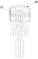
As shown in figure 1, the switch valve with a compact structure comprises a 01 coil, a 02 nozzle body, a 03 armature spring, a 04 armature and a 05 valve body, wherein the side surface of the 05 valve body is provided with an inlet channel 06, the middle part of the 05 valve body is provided with an outlet channel 07, the 01 coil is arranged on the 02 nozzle body, the 05 valve body is arranged on the 02 nozzle body, the 04 armature moves in the 02 nozzle body, the 03 armature spring is arranged between the 02 nozzle body and the 04 armature, and a 08 sealing surface is formed between the bottom of the 04 armature and the top of the 05 valve body to isolate the 06 inlet channel from the 07 outlet channel.
As shown in fig. 2, in order to enhance the electromagnetic force of the 01 coil, there is a modified structure including a 09 nut, the 09 nut being located on top of the 01 coil.
As shown in FIG. 3, in order to enhance the electromagnetic force of the 01 coil, there is a 02-nozzle-body deformation structure, which is divided into three parts, namely a 10-tight cap, a 11-magnetic-isolation sleeve and a 12-base, wherein the 01-tight cap and the 12-base are made of magnetic materials, and the 11-magnetic-isolation sleeve is made of non-magnetic materials.
As shown in fig. 4, in order to ensure the sealing between the 10-fastening cap, the 11-magnet isolation sleeve and the 12-base, there is a deformation structure comprising 13-sealing rings on the 10-fastening cap and the base, and annular grooves are opened between the 10-fastening cap and the 11-magnet isolation sleeve and between the 12-base and the 11-magnet isolation sleeve, and the 13-sealing rings are arranged in the annular grooves.
As shown in fig. 5 and 6, in order to enhance the tightness of the 08 sealing surface between the bottom of the 04 armature and the top of the 05 valve body, there are two variants of 14 sealing gaskets made of high polymer materials, one 14 sealing gasket is mounted on the bottom of the 04 armature, and the other 14 sealing gasket is mounted on the top of the 05 valve body.
As shown in fig. 7, in order to shorten the opening response time, a 04 armature deformation structure exists, and 15 vent holes communicated with the upper end face and the lower end face of the armature are formed in the 04 armature.
As shown in fig. 8, in order to adjust the lift of the armature, there is a modified structure including a 16-adjustment shim, which 16-adjustment shim is located between 02 the nozzle body and 05 the valve body.
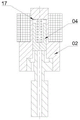
As shown in fig. 9, in order to reduce the impact between the 04 armature and the 02 nozzle body, there are two variants of structures containing a 17-cushion pad, one structure of the 17-cushion pad is mounted on the top of the 04 armature, and the other structure of the 17-cushion pad is mounted on the bottom of the hole in the 02 nozzle body.
The above description is only a preferred embodiment of the present invention and is not intended to limit the present invention, and various modifications and changes may be made by those skilled in the art. The utility model discloses be not limited to and be applied to solenoid valve technical field, still include other technical field that need apply the control valve product. Any modification, equivalent replacement, or improvement made within the spirit and principle of the present invention should be included in the protection scope of the present invention.
Claims (8)
1. A switch valve with a compact structure is characterized by comprising a coil, a nozzle body, an armature spring, an armature and a valve body, wherein an inlet channel is arranged on the side surface of the valve body, an outlet channel is arranged in the middle of the valve body, the coil is installed on the nozzle body, the valve body is installed on the nozzle body, the armature moves in the nozzle body, the armature spring is installed between the nozzle body and the armature, and a sealing surface is formed between the bottom of the armature and the top of the valve body to isolate the inlet channel from the outlet channel.
2. A switching valve of a compact structure according to claim 1, wherein there is a deformed structure including a nut, which is located on top of the coil.
3. The switch valve of claim 1, wherein there is a deformation of the nozzle body such that the nozzle body is divided into three parts of a locking cap, a magnetic spacer and a base, the locking cap and the base being made of a magnetic conductive material, the magnetic spacer being made of a non-magnetic conductive material.
4. A compact form of the switching valve as claimed in claim 3, wherein there is a modified form of the sealing ring included in the locking cap and the base, and a ring groove is formed between the locking cap and the magnetic shield and between the base and the magnetic shield, and the sealing ring is fitted in the ring groove.
5. The switch valve of claim 1, wherein there are two variants of the sealing gasket comprising a polymer material, the sealing gasket of one construction being mounted on the bottom of the armature and the sealing gasket of the other construction being mounted on the top of the valve body.
6. A compact switching valve as defined in claim 1 wherein there is a deformation of the armature and the armature has vent holes therein communicating the upper and lower faces of the armature.
7. A switch valve of a compact structure as claimed in claim 1, wherein there is a deformation structure including a shim, which is located between said nozzle body and said valve body.
8. The switch valve of claim 1, wherein there are two variants comprising a cushion pad, the cushion pad of one variant being mounted on top of the armature, and the cushion pad of the other variant being mounted on the bottom of the bore in the nozzle body.
Priority Applications (1)
| Application Number | Priority Date | Filing Date | Title |
|---|---|---|---|
| CN202221115616.XU CN218094537U (en) | 2022-05-11 | 2022-05-11 | Switch valve with compact structure |
Applications Claiming Priority (1)
| Application Number | Priority Date | Filing Date | Title |
|---|---|---|---|
| CN202221115616.XU CN218094537U (en) | 2022-05-11 | 2022-05-11 | Switch valve with compact structure |
Publications (1)
| Publication Number | Publication Date |
|---|---|
| CN218094537U true CN218094537U (en) | 2022-12-20 |
Family
ID=84460186
Family Applications (1)
| Application Number | Title | Priority Date | Filing Date |
|---|---|---|---|
| CN202221115616.XU Active CN218094537U (en) | 2022-05-11 | 2022-05-11 | Switch valve with compact structure |
Country Status (1)
| Country | Link |
|---|---|
| CN (1) | CN218094537U (en) |
-
2022
- 2022-05-11 CN CN202221115616.XU patent/CN218094537U/en active Active
Similar Documents
| Publication | Publication Date | Title |
|---|---|---|
| AU2011201570B2 (en) | Pneumatically actuated valve | |
| US4711269A (en) | Solenoid valve | |
| CN106641398B (en) | Large-caliber pilot unloading type electromagnetic valve | |
| CN218094537U (en) | Switch valve with compact structure | |
| CN215568315U (en) | Solenoid valve of accurate control stroke | |
| EP0319618B1 (en) | Solenoid valve | |
| CN117090984A (en) | Switch valve with compact structure | |
| CN106704615B (en) | Novel inserting plate type electromagnetic valve | |
| CN216951913U (en) | Pilot-operated type electromagnetic valve structure | |
| CN217207983U (en) | Plug-in type switch valve structure | |
| CN111075778B (en) | Transfer controlling means and hydraulic system | |
| CN215928391U (en) | Novel electromagnetic valve structure | |
| CN216743077U (en) | Electromagnetic valve and air conditioning system with same | |
| CN214618090U (en) | Normally open type two-position two-way electromagnetic valve | |
| CN216343576U (en) | Normally open solenoid valve for automobile braking system | |
| CN116498787A (en) | Pilot-operated electromagnetic valve structure | |
| CN114458769A (en) | Quick response's guide's formula solenoid valve structure | |
| CN115707891A (en) | Novel electromagnetic valve structure | |
| CN116624639A (en) | Plug-in type switch valve structure | |
| CN220435567U (en) | Poppet valve | |
| CN216643088U (en) | Small-size piston high frequency high pressure solenoid valve | |
| CN214008085U (en) | Electromagnetic valve with quick response of closed valve | |
| CN216975955U (en) | Large-flow high-frequency electromagnetic valve | |
| CN219734289U (en) | Bottom air supply pneumatic control valve | |
| CN211059451U (en) | Magnetic coupling type pneumatic control valve |
Legal Events
| Date | Code | Title | Description |
|---|---|---|---|
| GR01 | Patent grant | ||
| GR01 | Patent grant |