CN218094119U - Structure for preventing pulley bearing from axially moving - Google Patents
Structure for preventing pulley bearing from axially moving Download PDFInfo
- Publication number
- CN218094119U CN218094119U CN202222586917.7U CN202222586917U CN218094119U CN 218094119 U CN218094119 U CN 218094119U CN 202222586917 U CN202222586917 U CN 202222586917U CN 218094119 U CN218094119 U CN 218094119U
- Authority
- CN
- China
- Prior art keywords
- pulley
- bearing
- annular cover
- axial
- cover plate
- Prior art date
- Legal status (The legal status is an assumption and is not a legal conclusion. Google has not performed a legal analysis and makes no representation as to the accuracy of the status listed.)
- Active
Links
Images

Landscapes
- Mounting Of Bearings Or Others (AREA)
Abstract
The utility model discloses a structure for preventing axial movement of a pulley bearing, which comprises a pulley, a bearing, a retainer ring and an axial fixing part; the bearing is arranged in the pulley inner ring, two ends of the bearing extend out of the pulley inner ring for a preset length, a circle of groove is respectively arranged on the radial surfaces of the extending parts at two sides of the bearing and close to the side surface of the pulley, and a convex retaining ring is arranged in each groove; and two axial fixing parts are respectively arranged at two ends of the bearing, and are connected to the pulley through fasteners to axially fix the outer ring of the bearing. The utility model discloses use annular apron to carry out the axial fixity of bearing for the outer lane of bearing can bear great axial force, and does not separate with the pulley.
Description
Technical Field
The utility model relates to a pulley technical field, concretely relates to prevent pulley bearing axial float structure.
Background
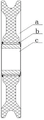
The center of the important guiding device of the steel wire rope of the pulley device needs to be provided with a bearing c to ensure that the pulley a can smoothly rotate on a pulley shaft, when the pulley a does not need to axially move on the pulley shaft, the inner ring and the outer ring of the bearing of the pulley a need to be axially fixed, the inner ring is generally axially fixed in a mode of a lantern ring on the pulley shaft, the outer ring rotates along with the pulley a, and a corresponding standard check ring b can be selected according to the specification of the bearing relative to the axial fixation of the pulley a, as shown in figure 1.
When the retainer rings on two sides are used for axially fixing the bearing in the prior art, only conventional axial positioning can be provided, and the axial force cannot be met if the axial force is too large.
SUMMERY OF THE UTILITY MODEL
Aiming at the defects existing in the prior art, in order to resist larger axial force, the structure for preventing the axial movement of the pulley bearing is designed, and the axial fixing bearing capacity of the pulley bearing can be better improved.
The utility model discloses realize according to following technical scheme:
the utility model discloses a structure for preventing axial movement of a pulley bearing, which comprises a pulley, a bearing, a retainer ring and an axial fixing part; the bearing is arranged in the pulley inner ring, two ends of the bearing extend out of the pulley inner ring for a preset length, a circle of groove is respectively arranged on the radial surfaces of the extending parts at two sides of the bearing and close to the side surface of the pulley, and a convex retaining ring is arranged in each groove; and two ends of the bearing are respectively provided with an axial fixing part, and the axial fixing parts are connected to the pulley through fasteners and then axially fix the outer ring of the bearing.
In some embodiments, the axial securing component is an annular cover plate; the annular cover plate is provided with a step circle, the annular cover plate is fixed behind the pulley, and the step circle of the annular cover plate is attached to the outer ring of the bearing to play a role in axial fixation.
In some embodiments, the annular cover plate is further provided with a plurality of first bolt holes, and the pulley is provided with a plurality of second threaded holes corresponding to the first threaded holes respectively; the fastener is a bolt, and the annular cover plate is fixed on the pulley after the bolt is matched with the first bolt hole and the second threaded hole.
In some embodiments, the bolts on the two side annular cover plates are symmetrically arranged by taking the radial center line of the pulley as the center.
In some embodiments, the outer race of the bearing is mounted in the pulley inner race with a tight fit so that the outer race of the bearing follows the pulley rotation.
The utility model discloses beneficial effect:
the utility model discloses use annular cover plate to carry out the axial fixity of bearing for the outer lane of bearing can bear great axial force, and not separate with the pulley.
Drawings
The accompanying drawings, which are included to provide a further understanding of the invention, are incorporated in and constitute a part of this specification, illustrate embodiments of the invention and together with the description serve to explain the invention without undue limitation. It is obvious that the drawings in the following description are only some embodiments, and that for a person skilled in the art, other drawings can be derived from them without inventive effort.
In the drawings:
FIG. 1 is a schematic view of a conventional structure for preventing axial play of a pulley bearing;
the attached drawings are as follows: a-pulley, b-retainer ring and c-bearing.
Fig. 2 is a schematic view of the structure for preventing axial movement of the pulley bearing of the present invention.
The attached drawings are as follows: 1-pulley, 2-retainer ring, 3-bearing, 4-annular cover plate and 5-bolt.
It should be noted that the drawings and the description are not intended to limit the scope of the inventive concept in any way, but to illustrate the inventive concept by those skilled in the art with reference to specific embodiments.
Detailed Description
To make the purpose, technical solution and advantages of the embodiments of the present invention clearer, the attached drawings in the embodiments of the present invention are combined below to clearly and completely describe the technical solution in the embodiments, and the following embodiments are used to illustrate the present invention, but do not limit the scope of the present invention.
In the description of the present invention, it should be noted that the terms "upper", "lower", "front", "rear", "left", "right", "vertical", "inner", "outer", and the like indicate orientations or positional relationships based on orientations or positional relationships shown in the drawings, and are only for convenience of description and simplification of description, but do not indicate or imply that the device or element referred to must have a specific orientation, be constructed and operated in a specific orientation, and thus, should not be construed as limiting the present invention.
In the description of the present invention, it is to be noted that, unless otherwise explicitly specified or limited, the terms "mounted," "connected," and "connected" are to be construed broadly, and may be, for example, fixedly connected, detachably connected, or integrally connected; can be mechanically or electrically connected; may be directly connected or indirectly connected through an intermediate. The specific meaning of the above terms in the present invention can be understood in specific cases to those skilled in the art.
As shown in FIG. 2, the structure for preventing the axial movement of the pulley bearing comprises a pulley 1, a bearing 3, a retainer ring 2 and an axial fixing component; the bearing 3 is arranged in the inner ring of the pulley 1, two ends of the bearing 3 extend out of the inner ring of the pulley 1 by a preset length, a circle of groove is respectively arranged on the radial surfaces of the extending parts at two sides of the bearing 3 and the side surfaces close to the pulley 1, and a convex retaining ring 2 is arranged in each groove; two ends of the bearing 3 are respectively provided with an axial fixing part, and the axial fixing parts are connected to the pulley 1 through fasteners and then axially fix the outer ring of the bearing 3.
A preferred embodiment of the above embodiment with respect to the axial securing member is given below:
with continued reference to fig. 2, the axially securing member is an annular cover plate 4; the annular cover plate 4 is provided with a step circle, the annular cover plate 4 is fixed behind the pulley 1, and the step circle of the annular cover plate 4 is attached to the outer ring of the bearing 3 to play an axial fixing role.
Further scheme: a plurality of first bolt holes are formed in the annular cover plate 4, and a plurality of second threaded holes corresponding to the first threaded holes are formed in the pulley 1; the fastener is bolt 5, fixes annular apron 4 on pulley 1 through bolt 5 after with first bolt hole, the cooperation of second screw hole.
Further scheme: the bolts 5 on the annular cover plates 4 at two sides are symmetrically arranged by taking the radial central line of the pulley 1 as the center.
Further scheme: the outer race of the bearing 3 is mounted in a tight fit in the inner race of the pulley 1 so that the outer race of the bearing 3 follows the rotation of the pulley 1.
Therefore, the utility model discloses a structure for preventing axial movement of a pulley bearing, which can ensure that the bearing outer ring is axially fixed relative to the pulley when the pulley is subjected to a large axial force; the axial play structure comprises two annular cover plates and a plurality of bolts, threaded holes used for being installed on the pulleys are formed in the annular cover plates, corresponding installation threaded holes are formed in the corresponding pulleys, so that the cover plates and the pulleys can be installed together through the bolts, and the annular cover plates can be installed in place to prevent the axial play of the bearing from compacting the bearing from two ends. Through the utility model discloses technical scheme's application, improvement pulley bearing's that can be better axial fixity bearing capacity.
In the description provided herein, numerous specific details are set forth. It is understood, however, that embodiments of the invention may be practiced without these specific details. In some instances, well-known methods, structures and techniques have not been shown in detail in order not to obscure an understanding of this description.
Furthermore, those skilled in the art will appreciate that although some embodiments described herein include some features included in other embodiments, not others, combinations of features of different embodiments are also meant to be within the scope of the invention and form different embodiments. For example, in the above embodiments, those skilled in the art can use the combination according to the known technical solutions and technical problems to be solved by the present application.
The above description is only a preferred embodiment of the present invention, and is not intended to limit the present invention in any way, and although the present invention has been disclosed with reference to the preferred embodiment, it is not intended to limit the present invention, and any person skilled in the art can make some changes or modifications to equivalent embodiments without departing from the scope of the present invention, and any simple modification, equivalent change and modification made to the above embodiments according to the technical essence of the present invention will still fall within the scope of the present invention.
Claims (5)
1. The utility model provides a prevent pulley bearing axial float structure which characterized in that:
comprises a pulley, a bearing, a retainer ring and an axial fixing component;
the bearing is arranged in the pulley inner ring, two ends of the bearing extend out of the pulley inner ring for a preset length, a circle of groove is respectively arranged on the radial surfaces of the extending parts at two sides of the bearing and close to the side surface of the pulley, and a convex retaining ring is arranged in each groove;
and two axial fixing parts are respectively arranged at two ends of the bearing, and are connected to the pulley through fasteners to axially fix the outer ring of the bearing.
2. The structure of claim 1, wherein the structure for preventing axial play of the pulley bearing comprises:
the axial fixing part is an annular cover plate;
the annular cover plate is provided with a stepped circle, the annular cover plate is fixed behind the pulley, and the stepped circle of the annular cover plate is attached to the outer ring of the bearing to achieve an axial fixing effect.
3. The structure of claim 2, wherein the pulley bearing is configured to prevent axial play of the pulley bearing, and further comprising:
the annular cover plate is also provided with a plurality of first bolt holes, and the pulley is provided with a plurality of second threaded holes respectively corresponding to the first threaded holes;
the fastener is a bolt, and the annular cover plate is fixed on the pulley after the bolt is matched with the first bolt hole and the second threaded hole.
4. A structure for preventing axial play of a pulley bearing according to claim 3, wherein:
the bolts on the annular cover plates on the two sides are symmetrically arranged by taking the radial center line of the pulley as the center.
5. The structure of claim 1, wherein the structure for preventing axial play of the pulley bearing comprises:
the outer ring of the bearing is arranged in the inner ring of the pulley in a tight fit mode, so that the outer ring of the bearing rotates along with the pulley.
Priority Applications (1)
| Application Number | Priority Date | Filing Date | Title |
|---|---|---|---|
| CN202222586917.7U CN218094119U (en) | 2022-09-29 | 2022-09-29 | Structure for preventing pulley bearing from axially moving |
Applications Claiming Priority (1)
| Application Number | Priority Date | Filing Date | Title |
|---|---|---|---|
| CN202222586917.7U CN218094119U (en) | 2022-09-29 | 2022-09-29 | Structure for preventing pulley bearing from axially moving |
Publications (1)
| Publication Number | Publication Date |
|---|---|
| CN218094119U true CN218094119U (en) | 2022-12-20 |
Family
ID=84456456
Family Applications (1)
| Application Number | Title | Priority Date | Filing Date |
|---|---|---|---|
| CN202222586917.7U Active CN218094119U (en) | 2022-09-29 | 2022-09-29 | Structure for preventing pulley bearing from axially moving |
Country Status (1)
| Country | Link |
|---|---|
| CN (1) | CN218094119U (en) |
-
2022
- 2022-09-29 CN CN202222586917.7U patent/CN218094119U/en active Active
Similar Documents
| Publication | Publication Date | Title |
|---|---|---|
| EP2475902B1 (en) | Snap-on cage bridge for rolling element bearings | |
| EP2417375B1 (en) | Brake disk | |
| DE102009017865A1 (en) | Generator arrangement for wind energy plant | |
| DE102006010590B4 (en) | Pulley for a traction drive | |
| CN218094119U (en) | Structure for preventing pulley bearing from axially moving | |
| JP2016168860A (en) | Bearing device for wheel | |
| US3739424A (en) | Suspended trolley | |
| JPS62222991A (en) | Modular gearless elevator drive | |
| US10961985B2 (en) | Wind turbine and methods including main shaft integrated with locking disc | |
| CN210502109U (en) | New energy automobile hub unit with lock catch assembly | |
| CN216618282U (en) | Bearing with dustproof and anti-pollution functions | |
| CN111022506A (en) | Assembled bearing | |
| CN218988524U (en) | Traction machine, braking structure thereof and elevator | |
| CN218325771U (en) | New energy automobile wheel hub bearing | |
| CN210528177U (en) | Steel wire rope guide wheel | |
| CN217842368U (en) | Anti-fracture ball bearing | |
| CN211288450U (en) | Bearing convenient to change inner shaft sleeve | |
| CN211778828U (en) | Servo motor gear box | |
| CN210509957U (en) | Hub unit bearing with double-row angle belt gear riveting structure | |
| CN220168517U (en) | Friction transmission structure of snowplow | |
| CN214367338U (en) | Novel axial connection device for hamster runner | |
| CN217574748U (en) | Heavy type traction seat structure | |
| CN213393135U (en) | Dustproof bearing of making an uproar that falls | |
| CN112832066B (en) | Vibration isolator for track floating plate | |
| CN219345262U (en) | Non-elevation high-speed combined ball bearing |
Legal Events
| Date | Code | Title | Description |
|---|---|---|---|
| GR01 | Patent grant | ||
| GR01 | Patent grant |